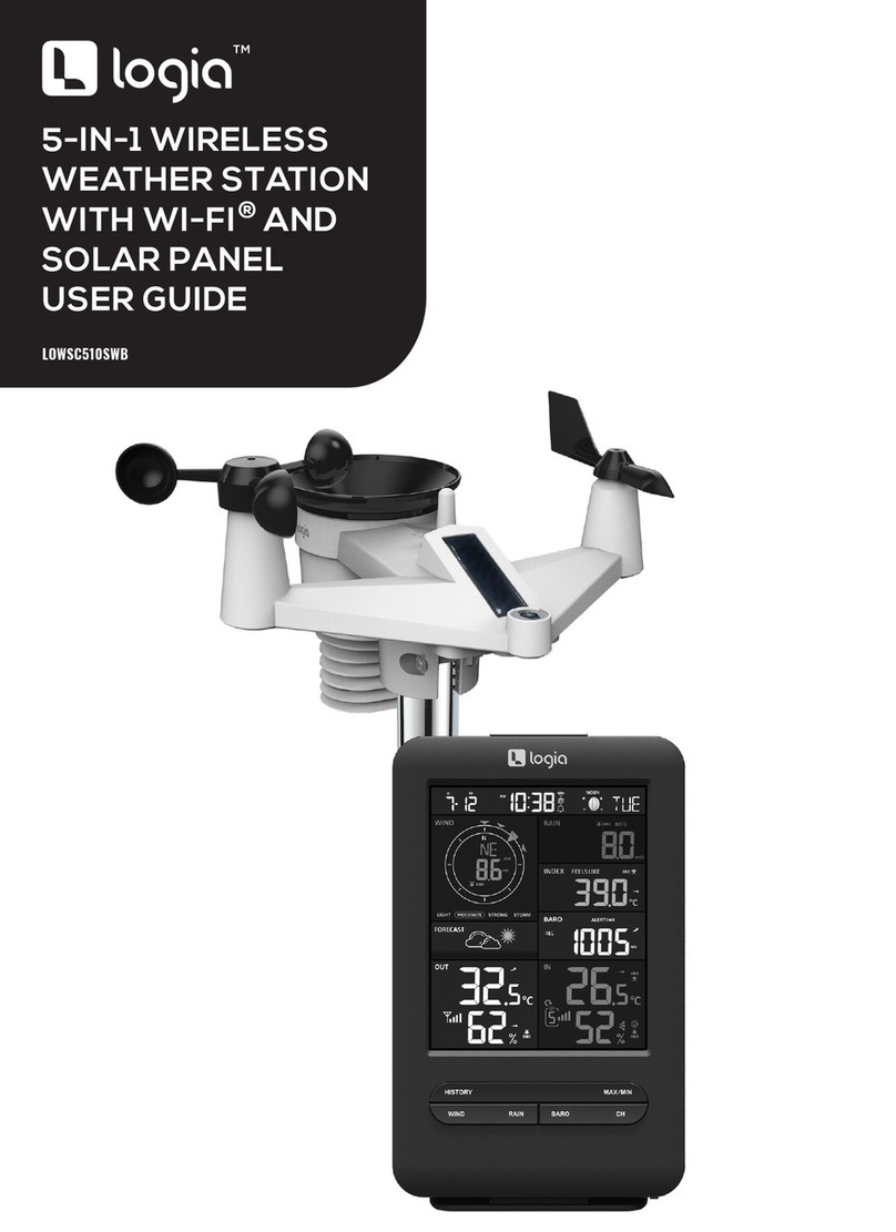
Logia LOWSC510WB User manual

2
Thank you for purchasing the Logia™5-in-1 Wireless Weather Station with WI-FI. This User
Guide is intended to provide you with guidelines to ensure that operation of this product is safe and
does not pose risk to the user. Any use that does not conform to the guidelines described in this User
Guide may void the limited warranty.
Please read all directions before using the product and retain this guide for reference. This product is
intended for household use only. It is not intended for commercial use.
This product is covered by a limited one-year warranty. Coverage is subject to limits and exclusions.
See warranty for details.
SAFETY PRECAUTIONS
PRODUCT FEATURES
PACKAGE CONTENTS
DISPLAY CONSOLE OVERVIEW
LCD DISPLAY OVERVIEW
WIRELESS WEATHER SENSOR OVERVIEW
WIRELESS WEATHER SENSOR SETUP
DISPLAY CONSOLE SETUP
WI-FI CONNECTION
CREATE WEATHER SERVER ACCOUNT
ACCESSING WEATHER DATA ONLINE
OTHER CONSOLE SETTINGS AND FUNCTIONS
CARE AND MAINTENANCE
SPECIFICATIONS
QUESTIONS?
3
4
5
6
7
8
10
13
15
20
23
24
34
35
39
TABLE OF CONTENTS

3
SAFETY PRECAUTIONS
1. Do not let children use or play with this device. It is not a toy.
2. Do not use any attachments not supplied or recommended by the manufacturer.
3. Do not place the appliance near open ames or heat sources. Fire, electric shock, product damage,
or injury might occur.
4. Do not mix old and new batteries in the display unit.
5. A low battery symbol will appear in the OUT or CH sections of the LCD display when battery
power is low on the console or weather sensor, respectively. Be sure to change the batteries
promptly to ensure the proper operation of the weather station.
6. Do not subject the display unit to excessive force or shock (do not throw the unit!), dust, extreme
high or low temperatures, or humidity/moisture. These can cause the unit to stop functioning as
well as present the risk of shock, re, or other hazards.
7. Do not cover the ventilation holes on the display with newspapers, curtains, or any other items.
8. Never immerse the display in water! If you spill any liquid on the display, dry it immediately with a
soft, lint-free cloth.
9. Do not use abrasive or corrosive materials to clean the display.
10. Do not tamper with the display or the weather vane’s internal components. This invalidates your
limited warranty.
11. Placing this product on certain types of wood may result in unintended damage to the nish,
for which Logia™ will not be responsible. Consult your furniture manufacturer’s instructions for
information on wood care.
12. Do not dispose of old batteries as unsorted municipal waste. Make sure to dispose of them properly
according to your local guidelines.
13. The main display console is only intended for use indoors.
QUESTIONS OR PROBLEMS? CONTACT US!
www.logiaweatherstation.com

4
PRODUCT FEATURES
1. Wireless 5-in-1 weather sensor measures wind speed, wind direction, rainfall, temperature, and
humidity.
2. No calibration needed! The product is fully pre-calibrated and mostly assembled; all you need to do
is install it and sync with the included display console.
3. Provides precise weather and environmental information directly from your own backyard, instead
of relying on a national weather station.
4. Color LCD display with dimmable backlight.
5. Can alert you to excessively high/low indoor or outdoor temperatures or humidity, high wind speeds,
extreme drops in barometric pressure, high heat indexes, low wind chills, and high/low dew points.
6. Syncs with installed WI-FI and online weather servers (Weather Undergound and Weathercloud) to
help you store and track weather data in your area, plus view live weather statistics and historical
weather trends.

5
PACKAGE CONTENTS
MAX/MINHISTORYCHANNEL
1. Wireless Weather Sensor (1)
2. Mounting Pole (1)
Plastic Exterior
3. Mounting Clamp (1)
4. Mounting Base (1)
5. Large Mounting Screws (4)
6. Large Hexagonal Nuts (4)
7. Large Washers (4)
8. Small Screws (2)
9. Small Hexagonal Nuts (2)
10. Rubber Pads for Mounting
Clamp
11. Display Console with
Kickstand (1)
12. Display Console Battery (1)
13. Display Console Power Cable (1)
14. User Guide
1
2
5
7
8
6
9
4
3
10
11
12
13
14

6
DISPLAY CONSOLE OVERVIEW
MAIN CONSOLE OVERVIEW
1. Kickstand
2. SNOOZE button
3. CHANNEL button
4. HISTORY button
5. MAX/MIN button
6. WIND button
7. INDEX button
8. BARO button
9. RAIN button
10. LCD Display (See overview
on page7
11. CLOCK SET button
12. ALARM button
13. Wall mount notch
14. ALERT button
15. button
16. button
17. Power connection
18. 12/24 button
19. °C/°F button
20. BARO UNIT button
21. SENSOR/WI-FI button
22. REFRESH button
23. Battery compartment
24. OFF/LO/HI button
25. RESET button
MAX/MINHISTORYCHANNEL
WI-FI
SENSOR RESETREFRESH
BARO
UNIT
1
2
3 4 5 6 7 8 9 10 17 18 19 20 21 22 23 24 25
11 12 13 14 15 16

7
LCD DISPLAY OVERVIEW
1. Temperature & humidity (indoor/CH)
2. Weather forecast
3. Time, date, & moon phase
4. Wind speed & direction
5. Temperature & humidity (outdoor)
6. Barometer
7. Rainfall
8. Weather index
1
4
5
6
7
8
2
3

8
WIRELESS WEATHER SENSOR OVERVIEW
MAIN DEVICE
1. Rain collector
2. Level
3. Antenna
4. Wind cups (anemometer)
5. Mounting pole
6. Sensor casing
7. Wind vane
8. Mounting base
9. Mounting clamp
10. Red LED indicator
11. RESET button
12. Battery compartment
13. Mounting clamp
screws
1
4
2
6
3
710
11
12
5
13
8
9

9
RAIN GAUGE
TEMPERATURE AND HUMIDITY SENSOR
WIND SENSOR
1. Rain collector
2. Tipping bucket
3. Drain holes
4. Rain sensor
1. Sensor shield
2. Temperature and
humidity sensor
1. Wind cups (anemometer)
2. Wind vane
1
1
1
2
2
2
3 4

10
WIRELESS WEATHER SENSOR SETUP
INSTALL BATTERIES
ASSEMBLE STAND AND POLE
1. Unscrew the door to the battery compartment on the underside of the main sensor unit.
2. Insert three (3) new AA alkaline batteries, making sure the polarities match up with the markings
inside the compartment.
1. Insert the top of the pole into the square hole at the bottom of the weather sensor. Ensure that the
arrow indicators are lined up as shown.
3. Replace the battery door, ensuring the watertight O-ring is properly aligned. This maintains the
water-resistant seal.
4. Replace the battery screw, making sure it is tightly fastened down. The red LED should begin
ashing every 12 seconds.

11
2. Insert the nut into the hexagonal hole by the sensor and hold it in place, then insert the screw
through the other side. Use a screwdriver to tighten the screw. Do not insert the screw rst, or the
nut may not line up correctly with the designated hole.
3. Insert the bottom of the pole into the square hole on the plastic stand, making sure the arrows are
lined up as shown.
Please note that there are two di erent ways you can attach the pole to the base, depending on how you
will be mounting it outdoors. If you will be fastening the sensor directly to a railing, use the option that
positions the stand perpendicular to the sensor pole. If you will be fastening it to a pole, use the slot
that positions the base parallel to the sensor pole.
2. The red LED will begin ashing every 12 seconds.

12
MOUNT THE SENSOR OUTDOORS
If securing to a railing, make sure the railing is made of suitable material, and screw directly through
the openings in the base stand into the railing until secure.
1. The wireless weather sensor should be mounted in an open area with no obstructions above and/
or around it, so that it can accurately measure the rain and wind.
2. The wind vane should be pointed due North (refer to the arrow on top of the unit) in order to be
properly oriented and receive accurate wind readings.
3. The mounting stand and included clamps should be secured to a post or pole, with a minimum of
4.9 ft. (1.5 m) ground clearance.
4. If securing to a pole, make sure you add the rubber pads to the clamp before fastening it with the
included screws. The pole should be between 1″-1.3″ in diameter.
4. Insert the nut into the hexagonal hole on the side of the stand and hold it in place, then insert the
screw through the other side. Use a screwdriver to tighten the screw.
Install the wireless 5-IN-1 sensor in an
open location with no obstructions above
and around the sensor for accurate
rain and wind measurement. Install
the sensor with the smaller end facing
the North to properly orient the wind
direction vane.
Secure the mounting stand and bracket
(included) to a post or pole, and allow
minimum 1.5m off the ground.
1.5 meter off
the ground
Add rubber
pads before
mount on
the pole
Point to
NORTH
Your console can pairing up with the wireless 5-IN-1 outdoor weather sensor and up to 7
optional wireless sensors. (Not included)
Remove the battery door of the console.
Insert a new button cell battery.
Replace the battery door.
The backup battery can backup: Time & Date, Max/Min & Past 24 hours weather records, Alert
setting values, offset value of weather data and Sensor(s) channel history.
The built-in memory can backup: Router setting and Weather server setting
Plug the power adaptor to power up the console.
Once the console power up, all the segments of the LCD will be shown.
The console will automatically start AP mode.
If no display appears on the LCD after you plug the adaptor, press key by using a
pointed object.
key in normal mode to adjust LCD viewing angle to t table stand or wall
mount situation.
AMOUNTING ON POLE
(POLE DIAMETER 1”-1.3”)
(25-33MM)
Point to NORTH
Add rubber
pads before
mount on
the pole
1.5 meter off the
ground

13
INSTALLING THE BACKUP BATTERY
POWERING THE DISPLAY CONSOLE
Your display console can pair with the wireless weather sensor as well as up to seven (7) optional
wireless hygro-thermo outdoor sensors (not included).
5. The mounting location should be within 492 ft. (150 m) of the location where you will be keeping
the display console with few obstructions and relatively clear sightlines. If there are multiple walls/
levels/buildings in between the sensor and the display console, the functionality could be
compromised and you will need less space between the two.
6. Use the built-in level to make sure the sensor is parallel with the ground.
1. Detach the table stand.
2. Unscrew the console battery door screw.
3. Remove the battery door.
4. Insert a new button cell battery.
5. Replace the battery door and tighten the screw.
NOTE: The backup battery can assist with backing up the time & date, MAX/MIN data, weather
records from the past 24 hours, alert settings, the oset value of weather data, and the sensor(s)
channel history. The built-in memory will backup router and weather server settings.
1. Connect the power cable to a wall outlet or power source and to the display console power
connection port.
2. The display console should power on, and all the segments of the LCD display screen should be shown.
3. The display console will automatically start AP mode.
DISPLAY CONSOLE SETUP
Screw
CR2032
BMOUNTING ON A RAILING

14
PAIRING THE WIRELESS WEATHER SENSOR WITH THE DISPLAY CONSOLE
SET THE LCD DISPLAY VIEWING ANGLE
CHANGING BATTERIES AND MANUAL PAIRING
Whenever you change the batteries in the sensor, you will need to manually repair it with the display
console. Follow these instructions to manually pair your console with the sensor.
1. Once your display console powers on, it should automatically search for and connect to the
wireless weather sensor. If the console does not connect within the rst 15 minutes, refer to the
following section, Changing Batteries and Manual Pairing, for instructions on manual pairing.
2. You will see the icon of an antenna blinking in the temperature and humidity (outdoor) section of
the display.
3. Once the pairing process completes, the antenna icon will appear solid (not blinking), and the
readings for outdoor temperature and humidity, wind speed, wind direction, and rainfall will
appear in their designated sections of the LCD display.
If you have the display console wall-mounted or on a table stand, the viewing angle may need
adjustment. Press or buttons while the display is in normal operating mode to adjust the
viewing angle.
NOTE: If nothing appears on the LCD display screen after you plug in the power adaptor, use a pin or
similar small object to press the RESET button.
1. Change the batteries in the wireless weather sensor.
2. Press the SENSOR/WI-FI button at the back of the console.
3. Press the RESET key on the underside of the wireless weather sensor. Make sure after pressing
the RESET key that the red LED indicator is ashing every 12 seconds.
WI-FI
SENSOR REFRESHBARO
UNIT
3
1 2

15
PAIRING ADDITIONAL WIRELESS SENSORS WITH THE DISPLAY CONSOLE
NOTE: Any time you press the RESET key underneath the wireless weather sensor, it generates a
new ID code for pairing with the console, and you will need to press the SENSOR/WI-FI button on the
console for the two devices to pair again.
The display console should automatically search and pair with any additional wireless hygro-thermo
outdoor sensors you install. You can also press the SENSOR/WI-FI button to search manually for the
sensor while on the channel where it should display. Once your sensor has paired, the sensor signal
strength indicator and weather information will appear in the temperature and humidity (outdoor)
section when you are on the channel associated with that sensor.
WI-FI CONNECTION
SET UP WI-FI CONNECTION
When you rst power up the console, or press and hold the SENSOR/WI-FI button for six (6) seconds,
the console LCD display will show the letters “AP” and an icon to signify that it has entered
Access Point (AP) mode. At this time it will be ready for the WI-FI settings to be adjusted.
Use your smartphone, tablet, or computer to connect to the console via WI-FI by following these steps:
1. On PC, open your WI-FI network settings. On Android™ or iOS devices, go to settings menu
and then select Connections/WI-FI to open the network settings.
2. Locate the display console’s SSID from the list. It should appear as PWS-XXXXXX (where all
the X’s are integers) in the list. Tap on the SSID to connect. This step will take several seconds.
paired up, the sensor signal strength indicator and weather information will appear on your
This unit is designed to automatically synchronize its calendar and clock when connected to
, the unit will automatically synchronize the time instantly and 12:00am per day
The time sync function only work with the PC software "W
ime sync up is according to your current PC time, so please ensure your PC time is
Once the PC time sync up the icon will appear in the
ou can also enable or disable auto time sync function by press and hold
Jot down your ID and key for the further setup step.
When you rst power up the console, or press and hold the
seconds in normal mode, the console LCD will show "AP" and "
entered AP (access point) mode, and is ready for WI-FI settings.
Use the smart phone, tablet, or computer to connect to the console through WI-FI.
In PC choose WiFi network settings or In Android / iOS choose setting →
console’s SSID: in the list and it will need several second to connect.
PC WI-FI network interface Android WI-FI network interface
Once connected, enter the following IP address into your internet browser’s address bar, to
access the console’s web interface:
http://192.168.1.1
Some browsers will treat as a search, so make sure you include header.
Recommended browsers, such as the latest version of Chrome, Safari, Edge, Firefox or
Opera.
Jot down your ID and key for the further setup step.
When you rst power up the console, or press and hold the
seconds in normal mode, the console LCD will show "AP" and "
entered AP (access point) mode, and is ready for WI-FI settings.
Use the smart phone, tablet, or computer to connect to the console through WI-FI.
In PC choose WiFi network settings or In Android / iOS choose setting →
console’s SSID: in the list and it will need several second to connect.
PWS-XXXXXX
PWS-XXXXXX
PC WI-FI network interface Android WI-FI network interface
Once connected, enter the following IP address into your internet browser’s address bar, to
access the console’s web interface:
http://192.168.1.1
Some browsers will treat as a search, so make sure you include header.
Recommended browsers, such as the latest version of Chrome, Safari, Edge, Firefox or
Opera.

16
3. Once you are connected to the display console, open up your internet or mobile web browser,
and enter the following address into the address bar: http://192.168.1.1 (make sure to include
the http:// or else the web browser may interpret the address as a search query). We
recommend using the latest version of reputable web browsers.
SET UP WEATHER SERVER CONNECTION
Once you are connected via WI-FI to the display console and have opened the settings page at
http://192.168.1.1, enter the following information into the web interface setup page. If you have
chosen not to use Weather Underground or Weathercloud’s servers, leave the check boxes unchecked.
Function firmware version: 1.00
WiFi firmware version: 1.00
nist.time.gov
Server URL:
Time server setup
WIFI Router setup
SETUP ADVANCED
Wunderground
Station ID:
WDw124
******
******
******
IPACIR23Wc
Weather server setup
Station key:
Router:
Add Router
Search
Security type:
Router Password:
WAP2
ROUTER_A
Apply
Language: English
Weathercloud
Station ID:
Station key:
Mac address 00:0E:C6:00:07:10
Press to search router Select the WI-FI router (SSID) you will connect to
Manually enter the SSID if not on the list
Select router’s security type (usually WAP2)
Enter new Station ID and Station key assigned
by Wunderground (Weather Underground)
Select time server
Press to complete the setting
SETUP page
Router’s password (leave blank if unsecured)
Press to allow add
router manually
Password record remark
(If you entered password)
Current ID and
key recorded (if any)
Current ID and key
recorded (if any)
Enter new Station ID and Station key
assigned by Weathercloud
Press “SETUP” icon
to SETUP page
If you don’t have Station ID and Station Keys available for the upload you need to rst create an account at the
respective weather servers of Weather Underground (WU) and WeatherCloud (WC), followed by registering
the product to obtain the ID and keys. For details, please refer to session on “CREATE WEATHER SERVER
ACCOUNT”.

17
NOTES: When the WI-FI setup is complete, your computer or mobile device will return to the default
WI-FI connection. If it does not, simply open your device’s wireless network settings and manually
reconnect.
While in AP mode, you can press and hold the SENSOR/WI-FI button for six (6) seconds to exit AP
mode. The display console will simply restore the previous AP settings.
WI-FI CONNECTION STATUS
TIME SERVER CONNECTION STATUS
ADVANCED SETTINGS VIA WEB INTERFACE
The following icons on the LCD display screen show the WI-FI status:
Once the display console has connected to the internet, it will attempt to connect to the internet time
server to obtain the UTC time. Once the connection is successful and the time has been updated, the
“SYNC” icon will appear above the WI-FI icon on the LCD.
Once you are connected via WI-FI to the display console and have opened the settings page at
http://192.168.1.1, clicking on the tab that says ADVANCED will open the following page. This page
will allow you to set and view specic calibration data of your display console, and also update the
rmware if you are on PC.
To display the correct time for your specic time zone, you’ll need to change the time zone in the
CLOCK setting mode from 00 (default) to your specic time zone (e.g. -5 for EST). If you don’t know
your time zone, you can look it up online.
1. In normal operating mode, press and hold the CLOCK SET button for two (2) seconds to enter
the clock setting menu.
2. Press the or buttons to adjust the time zone, and then press and hold the CLOCK SET
button for two (2) seconds to conrm and exit the menu. Please refer to the Setting the Time
section of the manual on page 24 for details of other available clock settings.
The time will automatically sync with the internet time server at 12:00AM and 12:00PM each day. If you
would like to force it to sync sooner than that, press the REFRESH button on the console to update the
time in the next minute.
Select the Wi-fi router (SSID) you will connect to
Manually enter the SSID if not on the list
Select router’s security type (usually WAP2)
Check to confirm upload to Weather Underground
Enter new Station ID and Station key assigned
by Wunderground (Weather Underground)
Check to confirm upload to Weathercloud
Select time server
Press to complete the setting
Router’s password (leave blank if unsecured)
Press to allow add
router manually
Password record remark
(If you entered password)
Current ID and
key recorded (if any)
Current ID and key
recorded (if any)
Enter new Station ID and Station key
assigned by Weathercloud
Solid: the display console is
connected to your wireless router
Flashing: the display console is
attempting to connect to your wireless router
Flashing: the display console is
currently in AP (access point) mode
Press “SETUP” icon
to SETUP page
Flashing: Console is trying to
connect to WI-FI router
” icon will appear on the LC

18
CALIBRATION
1. You may enter or change the o set and gain values for di erent measurement parameters,
while viewing the current o set and gain values next to the corresponding boxes.
2. Once you have completed your calibrations, press the APPLY button on the SETUP tab.
3. The current o set value will update to show the value that you entered (instead of the default
value). If you want to change the value, you can enter a new value in the box beside the
number (as in step 1). To update the value, again, press APPLY in the SETUP tab.
NOTE:
We do not recommend calibration of most values with the exception of Relative Pressure, which must
be correctly calibrated to re ect your distance above sea level to account for altitude e ects.
-800 ~ 800hpa / -23.62 ~ 23.62inHg / -601.5 ~ 601.5mmHg
Setting Range:
SETUP ADVANCED
Language: English
Temperature oC
Outdoor
Indoor
CH 1
CH 2
CH 3
CH 4
CH 5
CH 6
CH 7
Humidity %
Relative Pressure Offset:
Absolute Pressure Offset:
hpa
Range: -20 ~ 20
(Default: 0)
Current offset: 10Current offset: -9
Current offset: -5Current offset: 2
Current offset: -2Current offset: 3
Current offset: -2Current offset: 1.2
Current offset: -5Current offset: -0.2
Current offset: -3Current offset: -20.1
Current offset: -10Current offset: 11.5
Current offset: -3
Current offset: -3
(Default: 0)
Current offset: 10
(Default: 0)
Current offset: 0.2
Current offset: -5Current offset: 1
Pressure
Range: -20.0 ~ 20.0oC
-36.0 ~ 36.0oF (Default: 0.0)
**UV gain: Range: 0.01 ~ 10(Default: 1.00)
Current gain: 1.1
** Depends on outdoor sensor type
Wind speed gain:
**Wind direction:
Rain gain: Range: 0.5 ~ 1.5(Default: 1.00)
Range: -10 ~ 10(Default: 0o)
Range: 0.5 ~ 1.5(Default: 1.00)
Current gain: 0.85
Current offset: 2o
Current gain: 0.75
Function firmware version: 1.00
WiFi firmware version: 1.00
Temperature calibration section
Pressure calibration section
Rain calibration section
Wind calibration section
Select setting unit
Advanced page
Press ‘ADVANCED’ icon to view
the advanced settings page
Humidity calibration section
Select setting unit

19
UPDATING THE FIRMWARE
This display console supports OTA (over the air) Function Firmware and WI-FI System Firmware
updates via any web browser (not mobile browser) on a PC that is connected to WI-FI. The update
function for both types of updates can be found at the bottom of the Advanced Tab on the wireless
settings interface (see Advanced Settings via Web Interface on page 20.
Follow the steps below to update your device’s Function or WI-FI System Firmware
1. Download the latest version of the rmware (function or WI-FI) and save it to your PC.
Remember where you saved the le.
2. Press and hold the SENSOR/WI-FI button for six (6) seconds to put the display console into AP
mode, then connect the PC to the console (refer to steps in Set Up WI-FI Connection on page 18.
3. Click the button that says Browse next to the appropriate type of update that you downloaded
and navigate to the location where you saved the le.
4. Click the corresponding Upload button to transfer the update le to the console.
5. The le will install automatically once it is uploaded. You can view update progress on the
display console in the wind direction section (the number displayed will correspond to the
percentage completed, so 50 = 50% and so on).
You can also use the Apple ipad's "WunderStation" app to login your own weather station to
view the live data.
underStatio
To view your weather station live data in a web browser (PC or mobile version), please visit
https://weathercloud.net and sign in your own account.
icon inside the pull down menu of your station.
", " ", " " icon to view the live data of your weather
The console supports OTA rmware update capability. Its rmware may be updated over the
air anytime (whenever necessary) through any web-browser on a PC with WI-FI connectivity.
Update function, however, is not available through mobile/smart devices.
Two types of rmware updates are available, namely Function Firmware and System WI-FI
Firmware, and are located at the bottom of ADVANCED page.
firmware version
firmware version
Current Function
rmware version
Current WI-FI
rmware version
Download the latest version rmware (function or WI-FI) to your PC.
Set the Console into AP (access point) mode then connect the PC to the console (ref to
"SETUP WI-FI CONNECTION" section in previous page).
To update the Function rmware, click the Browse in Function rmware section and
browse to the location of the le you download in step 1. To update the WI-FI rmware, click
Browse in WI-FI rmware section.
Click the corresponding Upload
transfer the rmware le to console (indicated by
a transfer completion %).
Upload
30% ...
BrowseC:\download\PWS_SYS.bin
Upload
Browse
Function firmware version: 1.00
WiFi firmware version: 1.00
3
4
Once the console received the rmware le, it
executes the update automatically as indicated
by the update progress on display (i.e. 100 is
completion).
The console will restart once the update completed.
Function and WI-FI rmware cannot be updated at the same time, you need to update one by
Please keep connecting the power during the rmware update process.
Please make sure your PC's WI-FI connection is stable.
When the update process start, do not operate the PC and console.
During rmware update the console will stop upload data. It will reconnect to your WI-FI router
and upload the data again once the update success. If the console cannot connect to your
router, please end the SETUP page to setup again.
After the rmware updates, user might need to input the Weather Underground ID and
password again.
This console is designed to obtain the local time by synchronize with the assigned internet time
server. If you want to use it ofine, you can set the time and date manually. During the rst time
startup, press and hold the key for 6 seconds and let the console back to
normal mode.
In normal mode, press and hold key for 2 seconds to enter setting.
The setting sequence: Time Zone → → → → 12/24 hour format →
→ → → M-D/D-M format → Time sync ON/OFF → weekday Language.
key to change the value. Press and hold the key for quick-adjust.
key to save and exit the setting mode, or the unit will automatically
exit the setting mode 60 seconds later without pressing any key.
In normal mode, press key to switch between year and date display.
During the setting, you can press and hold key for 2 seconds to back to normal
model.
Download the latest version rmware (function or WI-FI) to your PC.
Set the Console into AP (access point) mode then connect the PC to the console (ref to
"SETUP WI-FI CONNECTION" section in previous page).
To update the Function rmware, click the Browse in Function rmware section and
browse to the location of the le you download in step 1. To update the WI-FI rmware, click
Browse in WI-FI rmware section.
Click the corresponding Upload
transfer the rmware le to console (indicated by
a transfer completion %). Upload
30% ...
BrowseC:\download\PWS_SYS.bin
Upload
Browse
Function firmware version: 1.00
WiFi firmware version: 1.00
Once the console received the rmware le, it
executes the update automatically as indicated
by the update progress on display (i.e. 100 is
completion).
The console will restart once the update completed.
Function and WI-FI rmware cannot be updated at the same time, you need to update one by
Please keep connecting the power during the rmware update process.
Please make sure your PC's WI-FI connection is stable.
When the update process start, do not operate the PC and console.
During rmware update the console will stop upload data. It will reconnect to your WI-FI router
and upload the data again once the update success. If the console cannot connect to your
router, please end the SETUP page to setup again.
After the rmware updates, user might need to input the Weather Underground ID and
password again.
This console is designed to obtain the local time by synchronize with the assigned internet time
server. If you want to use it ofine, you can set the time and date manually. During the rst time
startup, press and hold the key for 6 seconds and let the console back to
normal mode.
In normal mode, press and hold key for 2 seconds to enter setting.
The setting sequence: Time Zone → → → → 12/24 hour format →
→ → → M-D/D-M format → Time sync ON/OFF → weekday Language.
key to change the value. Press and hold the key for quick-adjust.
key to save and exit the setting mode, or the unit will automatically
exit the setting mode 60 seconds later without pressing any key.
In normal mode, press key to switch between year and date display.
During the setting, you can press and hold key for 2 seconds to back to normal
model.

20
6. The console will restart once the update completes.
NOTES:
• You cannot update the Function Firmware and WI-FI Firmware at the same time. Updates must be
installed one by one.
• Make sure the power cable remains connected during the update process.
• Make sure your PC’s wireless connection is stable.
• Once the update process starts, do not try to do anything else on your PC or on the display console.
• During the rmware update process, the console will stop uploading data temporarily. It will
reconnect to your router and resume uploading data once the update is complete. If the console
cannot connect to your router, you may need to set up the WI-FI connection again, following the
steps on page 18.
• Once your rmware update completes, you may need to input your Weather Underground ID and
password again on the SETUP tab of the wireless interface.
CREATE WEATHER UNDERGROUND ACCOUNT
1. Visit the Weather Underground website at https://www.wunderground.com and click the link that
says “JOIN”. Follow the instructions to create an account.
NOTE: Please use a valid email address to register your account.
2. Once you have created your account and completed the email validation process, return to the
Weather Underground website. Click the dropdown link at the top of the site that says MORE, and
then select Add Weather Station from the dropdown menu.
3. Follow the instructions on screen to enter your weather station information. Step 2 will ask you to
enter a name for your weather station (get creative if you want, but don’t forget the name you
gave it!) and choose your station hardware (choose “other”). Once you complete this section, click
Submit to generate your unique Station ID and key.
Your display console can upload weather data to Weather Underground and/or Weathercloud via your
WI-FI router.
NOTE: Logia™ does not own Weather Underground or Weathercloud, and these instructions are liable
to change without notice due to changes in either website.
CREATE WEATHER SERVER ACCOUNT
Other manuals for LOWSC510WB
1
Table of contents
Other Logia Weather Station manuals

Logia
Logia LOWSC7110FWB8 User manual
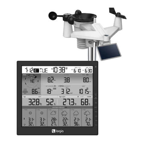
Logia
Logia LOWSC710B User manual

Logia
Logia LOWSL710FWB7 User manual

Logia
Logia LOWSCB711SAB User manual

Logia
Logia LOWSC715FWB10 User manual
Logia
Logia LOWSC713SWB User manual
Logia
Logia LOWSC715FWB10 User manual
Logia
Logia LOWSB510PB User manual

Logia
Logia LOWSC510SWB User manual

Logia
Logia LOWSB510PB User manual