16 17
The feels like temperature index determines what temperature it actually feels like outside, taking into account
factors like wind chill and the heat index.
The heat index is determined by the wireless weather sensor’s temperature and humidity readings when the
temperature is between 79 °F (26 °C) and 120 °F (50 °C).
FEELS LIKE
HEAT INDEX
Wind chill or windchill is the lowering of temperature due to the passing-ow of lower-temperature air.
Wind chill is determined by a combination of the wireless weather sensor’s temperature and wind speed data.
The dew point is the temperature below which the water vapor in air at constant barometric pressure
condenses into liquid water at the same rate at which it evaporates. The condensed water is called dew
when it forms on a solid surface.
The dew point temperature is determined by the temperature and humidity data from the wireless
weather sensor.
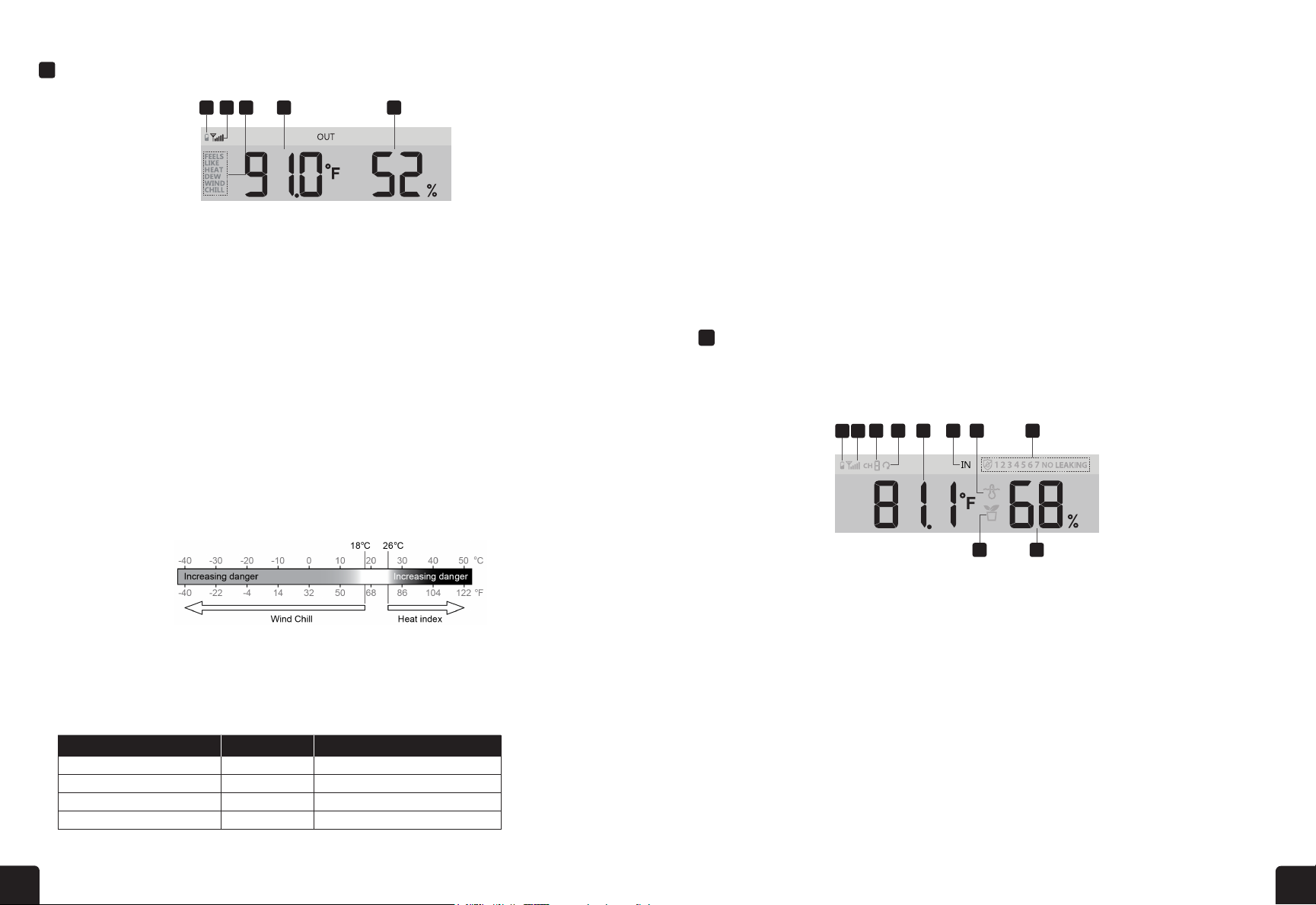
This section can show reading and status of the optional indoor hygro-thermo sensor(s) and water leak
sensor(s).
1. Outdoor sensor low battery indicator
2. Outdoor sensor signal indicator
3. Temperature index mode indicator
4. Outdoor temperature reading
5. Outdoor humidity reading
NOTES: If temperature/humidity is below the measurement range, the reading will show “Lo”.
If temperature/humidity is above the measurement range, the reading will show “HI”.
Press DOWN/INDEX button to switch between Outdoor temperature, Feels Like, Heat Index, Wind
Chill, and Dew Point.
1. Low battery indicator for CH sensor
2. Sensor signal strength icon
3. Channel number icon
4. Auto loop icon
5. Temperature reading section
6. Indoor icon
7. Floating pool sensor icon
8. Water leak sensor status
9. Soil moisture sensor icon
10. Humidity reading section
OUTDOOR TEMPERATURE, HUMIDITY & TEMPERATURE WIND CHILL
DEW POINT
15
NOTE:
- This is on-line weather forecast service, please keep the console connected to ProWeatherLive, you can
refer to section 5 and 6 for the WI-FI and PWL setup.
- Please input correct location for your device in ProWeatherLive "Edit device" page.
- If the Wi-Fi connectivity is not stable for over 3 hours, the weather forecast will not be shown and the
icon will disappear.
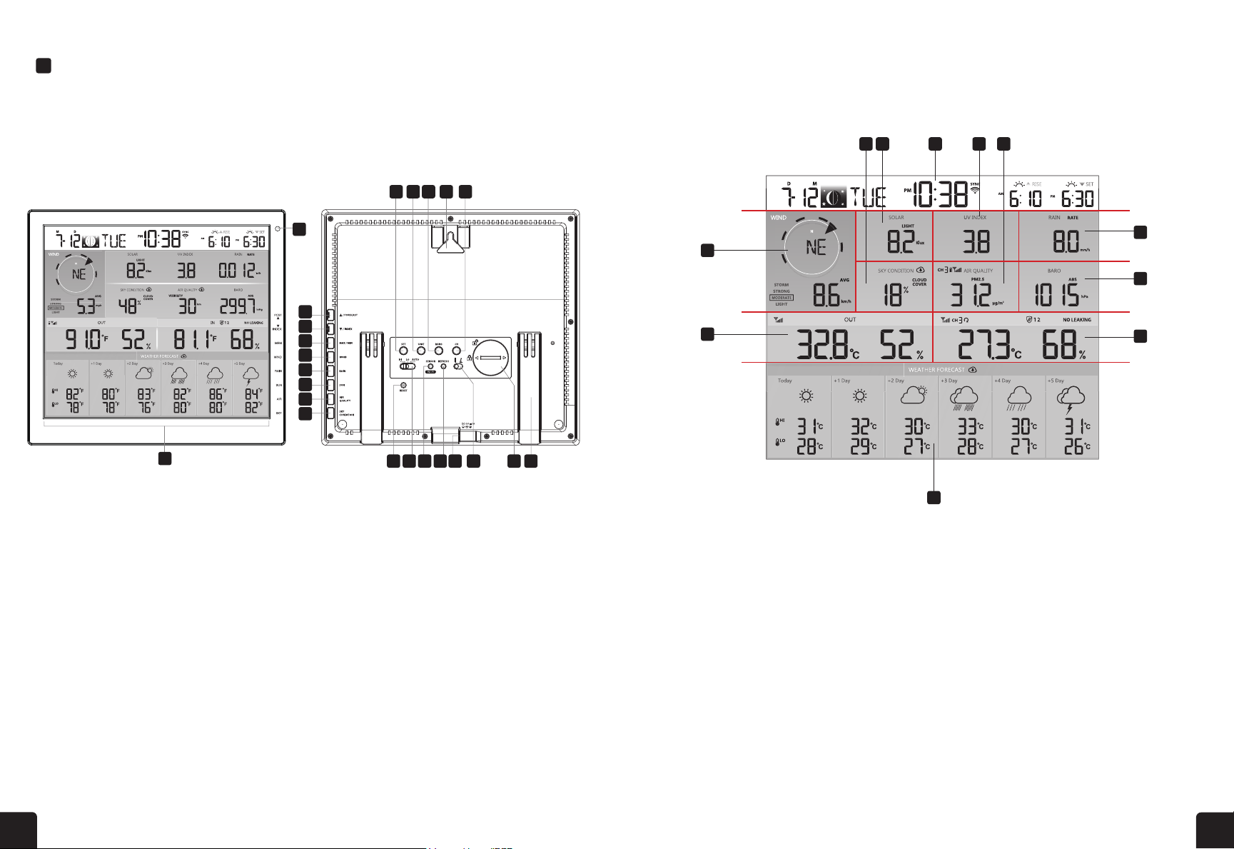
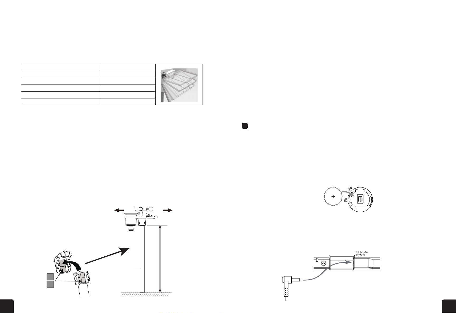
4.3.4 OUTDOOR TEMPERATURE, HUMIDITY & TEMPERATURE INDEX
1.Outdoor sensor signal indicator to show the signal
receiving strength
2.Outdoor sensor low battery indicator
3.Temperature index mode indicator
4.Outdoor Humidity reading
5.Outdoor Temperature reading
3
1
2
4
5
NOTE:
- If temperature / humidity is below the measurement range, the reading will show “Lo”. If temperature /
humidity is above the measurement range, the reading will show “HI”.
- Press [ / INDEX ] key to switch between Outdoor temperature, Feels Like, Heat Index, Wind Chill, and
Dew Point.
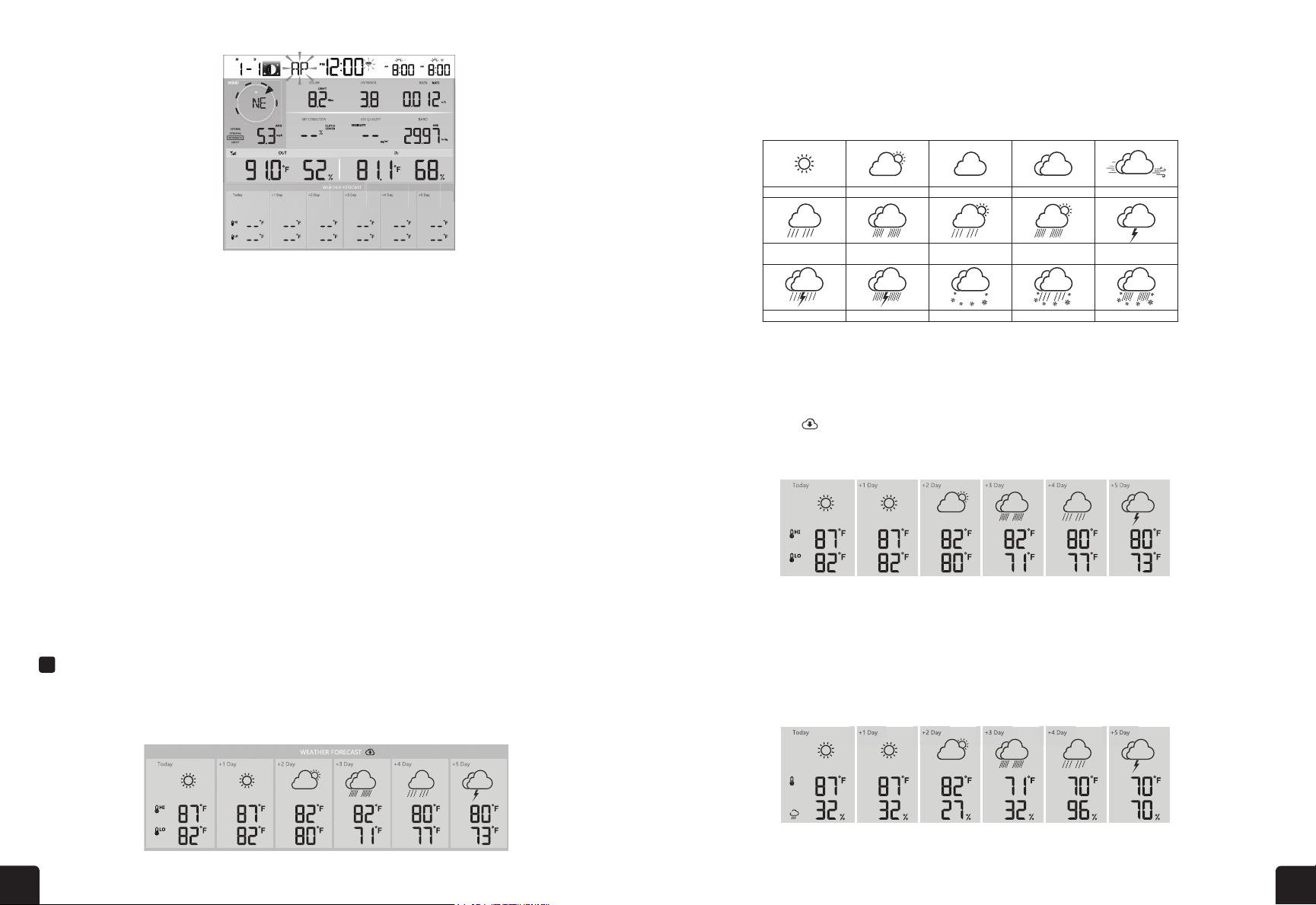
4.3.4.1 FEELS LIKE
Feels Like Temperature shows what the outdoor temperature will feel like. It’s a collective
mixture of Wind Chill factor (18°C or below) and the Heat Index (26°C or above). For
temperatures in the region between 18.1°C to 25.9°C where both wind and humidity are less
signicant in aecting the temperature, the device will show the actual outdoor measured
temperature as Feels Like Temperature.
4.3.4.2 HEAT INDEX
The heat index which is determined by the wireless 7-IN-1 sensor's temperature & humidity data
when the temperature is between 26°C (79°F) and 50°C (120°F).
Heat Index range Warning Explanation
27°C to 32°C (80°F to 90°F) Caution Possibility of heat exhaustion
33°C to 40°C (91°F to 105°F) Extreme Caution Possibility of heat dehydration
41°C to 54°C (106°F to 129°F) Danger Heat exhaustion likely
≥55°C (≥130°F) Extreme Danger Strong risk of dehydration / sun stroke
4.3.4.3 WIND CHILL
A combination of the wireless 7-IN-1 sensor's temperature and wind speed data determines the
current wind chill factor. Wind chill number are always lower than the air temperature for wind
values where the formula applied is valid (i.e. due to limitation of formula, actual air temperature
higher than 10°C with wind speed below 9km/h may result in erroneous wind chill reading).
INDOOR/CHANNELS TEMPERATURE & HUMIDITY
Beaufort
Scale Level Description Wind Speed Land Condition
0 Calm Calm. Smoke rises vertically
1 Light air
2 Light breeze
3 Gentle breeze
4 Moderate breeze
5 Fresh breeze
6 Strong breeze
7 High wind
< 1 km/h
< 1 mph
< 1 knot
.< 0 3 m/s
.1 1 ~ 5km/h
1 ~ 3 mph
1 ~ 3 knot
. .0 3 ~ 1 5 m/s
6 ~ 11 km/h
4 ~ 7 mph
4 ~ 6 knot
. .1 6 ~ 3 3 m/s
12 ~ 19 km/h
8 ~ 12 mph
7 ~ 10 knot
. .3 4 ~ 5 4 m/s
20 ~ 28 km/h
13 ~ 17 mph
11 ~ 16 knot
. .5 5 ~ 7 9 m/s
29 ~ 38 km/h
18 ~ 24 mph
17 ~ 21 knot
. .8 0 ~ 10 7 m/s
39 ~ 49 km/h
25 ~ 30 mph
22 ~ 27 knot
. .10 8 ~ 13 8 m/s
50 ~ 61 km/h
31 ~ 38 mph
28 ~ 33 knot
. .13 9 ~ 17 1 m/s
Smoke drifts indicate wind
direction. Leaves and wind
vanes are stationary.
Wind can be felt on exposed
skin. Leaves rustle. Wind
vanes begin to move.
Leaves and small twigs
constantly moving, light
flags extended.
Dust and loose paper
raised. Small branches
begin to move.
Branches of a moderate
size move. Small trees in
leaf begin to sway.
Whole trees in motion.
Eort needed to walk
against the wind.
Some twigs broken from
trees. Cars veer on the
road. Progress on foot is
seriously impeded.
Some branches break o trees,
and some small trees blow
over. Construction/temporary
signs and barricades blow over.
Trees are broken o or
uprooted, structural
damage likely.
Widespread vegetation
and structural
damage likely.
Severe widespread damage to
vegetation and structures.
Debris and unsecured objects
are hurled about.
Large branches in motion.
Whistling heard in overhead wires.
Umbrella use becomes dicult.
Empty plastic bins tip over.
8 Gale
9 Strong gale
10 Storm
11 Violent storm
12 Hurricane force
62 ~ 74 km/h
39 ~ 46 mph
34 ~ 40 knot
17. 2 ~ 20.7 m/s
75 ~ 88 km/h
47 ~ 54 mph
41 ~ 47 knot
20.8 ~ 24.4 m/s
89 ~ 102 km/h
55 ~ 63 mph
48 ~ 55 knot
24.5 ~ 28.4 m/s
103 ~ 117 km/h
64 ~ 73 mph
56 ~ 63 knot
28.5 ~ 32.6 m/s
≥ 118 km/h
≥ 74 mph
≥ 64 knot
≥ 32.7m/s
Exposure level Low Moderate High Very high Extreme
UV index 1 2 3 4 5 6 7 8 9 10 11 12~16
Sunburn time N/A 45 minutes 30 minutes 15 minutes 10 minutes
Recommended
protection
N/A Moderate or high UV level! Suggest to
wear sunglasses, broad brim hat and
long-sleeved clothing.
Very high or Extreme UV level! Suggest to wear
sunglasses, broad brim hat and long-sleeved
clothing, If you have to stay outdoors, make
sure to seek shade.
Level Light Moderate Strong Storm
Speed
4.3.7 WATER LEAK (OPTIONAL LEAK SENSOR)
You can add up to 7 additional Water Leak sensors (optional, refer
to section 3.2.1)
The channel number(s) of the corresponding water leak sensor(s)
added to the console will be shown with the NO LEAKING icon.
When water leaking is detected, the channel number of the sensor
NOTE:
When low battery is detected, the channel number of the sensor detecting the low battery
y 4 seconds.
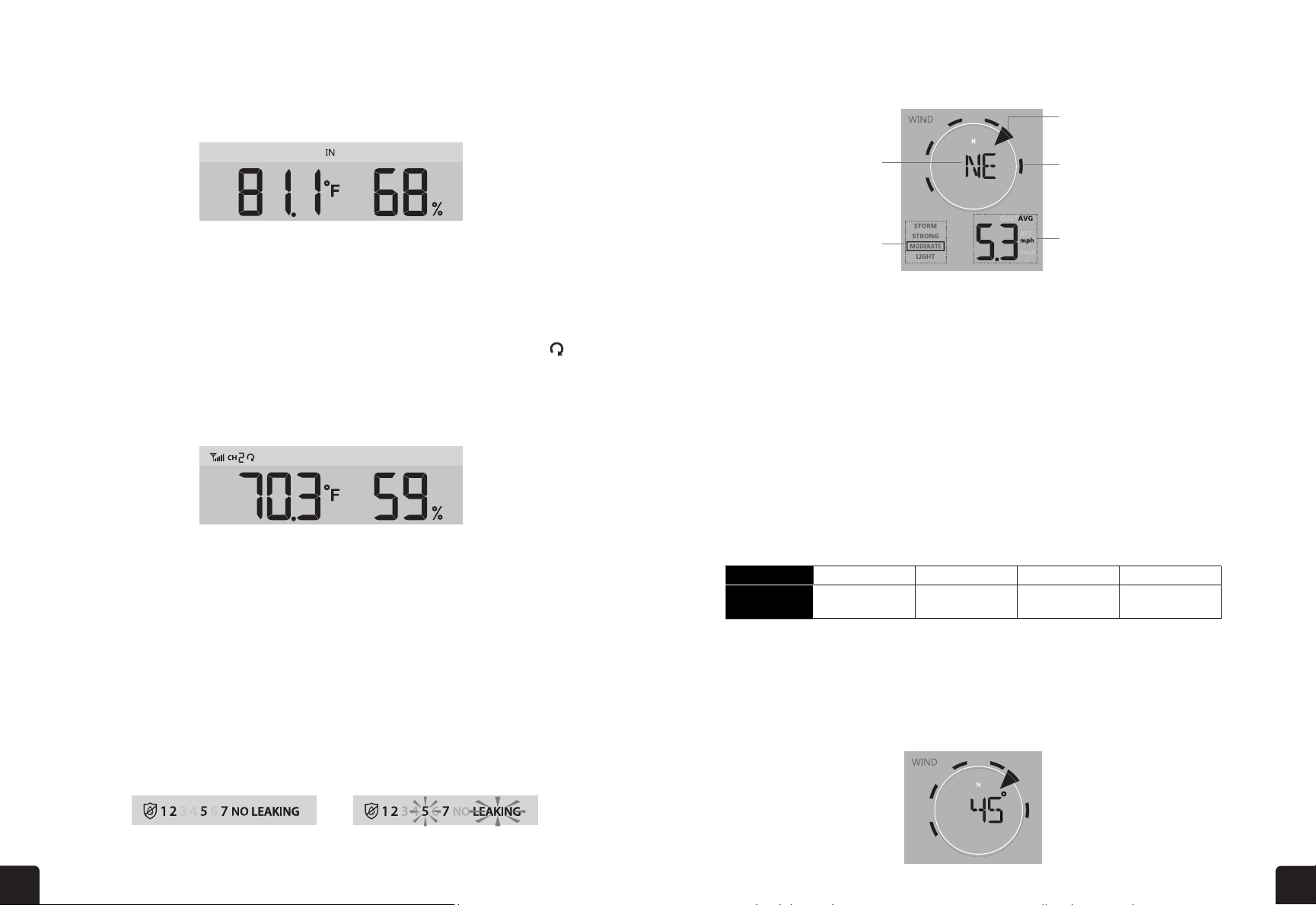
4.3.8 WIND
4.3.8.1 WIND SPEED AND DIRECTION SECTION OVERVIEW
W
Real time wind
direction indicator
Average / gust
wind speed or
Beaufort scale
Wind direction
ind speed level
indicator
Past wind directions
indicator of last 5
minutes (maximum 6)
A solid arrow indicates the current real-time wind direction, whereas the bars indicate up to six
4.3.8.2 WIND SPEED, GUST AND BEAUFORT SCALE DIPSLAY
2-8 mph
3-13 km/h
9-25 mph
14-41 km/h
26-54 mph
42-87 km/h
≥ 55 mph
≥ 88 km/h
Daily MAX
reading Daily MIN
reading MAX reading
since last reset MIN reading
since last reset
15
NOTE:
- This is on-line weather forecast service, please keep the console connected to ProWeatherLive, you can
refer to section 5 and 6 for the WI-FI and PWL setup.
- Please input correct location for your device in ProWeatherLive "Edit device" page.
- If the Wi-Fi connectivity is not stable for over 3 hours, the weather forecast will not be shown and the
icon will disappear.
4.3.4 OUTDOOR TEMPERATURE, HUMIDITY & TEMPERATURE INDEX
1.Outdoor sensor signal indicator to show the signal
receiving strength
2.Outdoor sensor low battery indicator
3.Temperature index mode indicator
4.Outdoor Humidity reading
5.Outdoor Temperature reading
3
1
2
4
5
NOTE:
- If temperature / humidity is below the measurement range, the reading will show “Lo”. If temperature /
humidity is above the measurement range, the reading will show “HI”.
- Press
[ / INDEX ] key
to switch between Outdoor temperature, Feels Like, Heat Index, Wind Chill, and
Dew Point.
4.3.4.1 FEELS LIKE
Feels Like Temperature shows what the outdoor temperature will feel like. It’s a collective
mixture of Wind Chill factor (18°C or below) and the Heat Index (26°C or above). For
temperatures in the region between 18.1°C to 25.9°C where both wind and humidity are less
temperature as Feels Like Temperature.
4.3.4.2 HEAT INDEX
The heat index which is determined by the wireless 7-IN-1 sensor's temperature & humidity data
when the temperature is between 26°C (79°F) and 50°C (120°F).
Heat Index range Warning Explanation
81 °F – 90 °F (27 °C – 32 °C) Caution Possibility of heat exhaustion
91 °F – 104 °F (33 °C – 40 °C) Extreme Caution Possibility of heat dehydration
106 °F – 129 °F (41 °C – 54 °C) Danger Heat exhaustion highly likely
≥ 131 °F (≥ 55 °C) Extreme Danger Strong risk of dehydration/ heatstroke
No signal Weak signal Good signal
Outdoor 7-in-1 sensor
Hygro-thermo
sensor channel
Other optional sensor
Stable: Console is in
connection with WI-FI router
Flashing: Console is trying
to connect to WI-FI router
Mode Setting procedure
1 Hour Press [ / INDEX ] or [ / MODE ] key to adjust the hour
2 Minute Press [ / INDEX ] or [ / MODE ] key to adjust the minute
3 12/24 hour format Press [ / INDEX ] or [ / MODE ] key to select 12 or 24 hour
format
4 Year Press [ / INDEX ] or [ / MODE ] key to adjust the year
5 Month Press [ / INDEX ] or [ / MODE ] key to adjust the month
6 Day Press [ / INDEX ] or [ / MODE ] key to adjust the day
7 M-D/D-M format Press [ / INDEX ] or [ / MODE ] key to select "Month / Day" or
"Day / Month" display format
8 Time sync ON/OFF Press [ / INDEX ] or [ / MODE ] key to enable or disable Time Sync function.
If you want to set the time manually, you should set Time Sync OFF
9 Weekday language Press [ / INDEX ] or [ / MODE ] key to select weekday display language
Alarm o Alarm on Alarm with ice-alert
Mode Setting procedure
1 Temperature unit Press [ / INDEX ] or [ / MODE ]key to select °C or °F
2 Rain unit Press [ / INDEX ] or [ / MODE ]key to select mm or in
3 Wind speed unit Press [ / INDEX ] or [ / MODE ]key to select m/s, km/h, knots or
mph
4 Baro pressure unit Press [ / INDEX ] or [ / MODE ]key to select hPa, inHg or mmHg
5 Light intensity Press [ / INDEX ] or [ / MODE ]key to select Klux, Kfc or W/m2
18
4.3.5.1 OVERVIEW
1.Low battery indicator for CH sensor
2.Sensor signal strength icon
3.Channel number
4.Auto loop icon
5.Temperature reading section
6.Indoor icon
7.Floating pool sensor icon
8.Water leak sensor status section
9.Soil moisture sensor icon
10. Humidity reading section
4.3.5.2 INDOOR TEMPERATURE & HUMIDITY
The indoor reading is default mode of the console, which
shows the temperature and humidity reading of indoor.
4.3.6 MULTI-CHANNEL AND SCROLL MODE FOR OPTIONAL SENSORS
You can add up to 7 additional Thermo-Hygrometer
sensor (optional, refer to section 3.2). Press the [ CH ]
key to switch between indoor and Channels 1 to 7.
For auto-scroll function, just press and hold the [ CH ]
key for 3 seconds and the icon will appear next to CH.
The console will scroll the readings of all the sensors
every 3 seconds.
This mode shown below information:
- Channel number of the current sensor
- Temperature and humidity reading of this sensor
- Signal strength of this sensor.
- Sensor type icon (for water pool or soil moisture sensor)
4.3.7 WATER LEAK (OPTIONAL LEAK SENSOR)
You can add up to 7 additional Water Leak sensors (optional, refer
to section 3.2)
The channel number(s) of the corresponding water leak sensor(s)
added to the console will be shown with the NO LEAKING icon.
When water leaking is detected, the channel number of the sensor
detecting the leaking will ash together the LEAKING icon.
NOTE:
When low battery is detected, the channel number of the sensor detecting the low battery
condition will ash once every 4 seconds.
17
4.3.4 OUTDOOR TEMPERATURE, HUMIDITY & TEMPERATURE INDEX
1.Outdoor sensor low battery indicator
2.Outdoor sensor signal indicator to show the signal
receiving strength
3.Temperature index mode indicator
4.Outdoor Temperature reading
5.Outdoor Humidity reading
NOTE:
- If temperature / humidity is below the measurement range, the reading will show “Lo”. If temperature /
humidity is above the measurement range, the reading will show “HI”.
- Press [ / INDEX ] key to switch between Outdoor temperature, Feels Like, Heat Index, Wind Chill, and
Dew Point.
4.3.4.1 FEELS LIKE
Feels Like Temperature shows what the outdoor temperature will feel like. It’s a collective
mixture of Wind Chill factor (18°C or below) and the Heat Index (26°C or above). For
temperatures in the region between 18.1°C to 25.9°C where both wind and humidity are less
signicant in affecting the temperature, the device will show the actual outdoor measured
temperature as Feels Like Temperature.
4.3.4.2 HEAT INDEX
The heat index which is determined by the wireless 7-IN-1 sensor's temperature & humidity data
when the temperature is between 26°C (79°F) and 50°C (120°F).
Heat Index range Warning Explanation
27°C to 32°C (80°F to 90°F) Caution Possibility of heat exhaustion
33°C to 40°C (91°F to 105°F) Extreme Caution Possibility of heat dehydration
41°C to 54°C (106°F to 129°F) Danger Heat exhaustion likely
≥55°C (≥130°F) Extreme Danger Strong risk of dehydration / sun stroke
4.3.4.3 WIND CHILL
A combination of the wireless 7-IN-1 sensor's temperature and wind speed data determines the
current wind chill factor. Wind chill number are always lower than the air temperature for wind
values where the formula applied is valid (i.e. due to limitation of formula, actual air temperature
higher than 10°C with wind speed below 9 km/h may result in erroneous wind chill reading).
4.3.4.4 DEW POINT
- The dew point is the temperature below which the water vapor in air at constant barometric pressure
condenses into liquid water at the same rate at which it evaporates. The condensed water is called dew
when it forms on a solid surface.
- The dew point temperature is determined by the temperature & humidity data from wireless 7-IN-1 sensor.
4.3.5 INDOOR / CHANNELS TEMPERATURE & HUMIDITY
This section can show reading and status of the indoor, optional hygro-thermo sensor(s) and
water leak sensor(s).
1 2 3 4 5
1 2 3 4 8
9 10
5 6 7