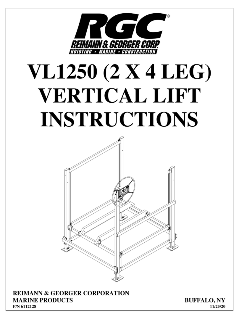
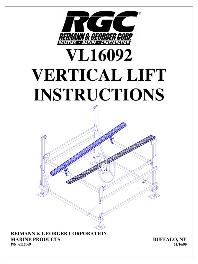
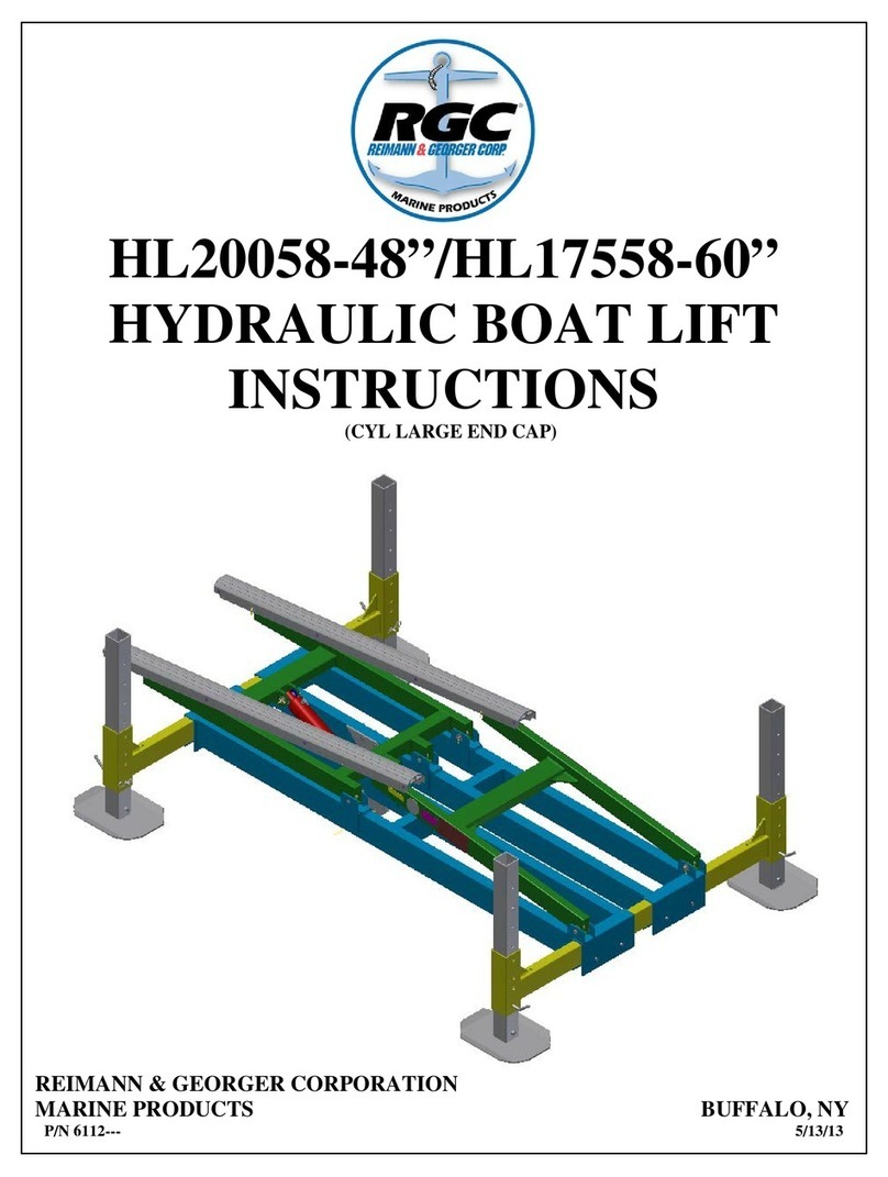
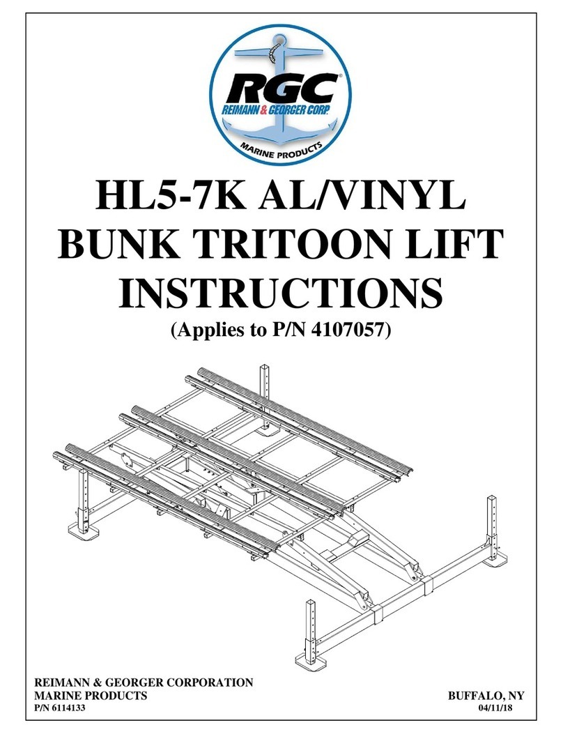
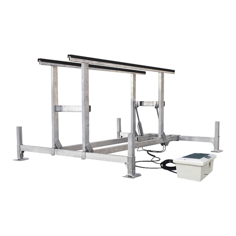
RGC HL5-7K User manual

HL5-7K PLATFORM
LIFT INSTRUCTIONS
REIMANN & GEORGER CORPORATION
MARINE PRODUCTS BUFFALO, NY
P/N 6114205 10/16/14

TABLE OF CONTENTS
CHAPTER TITLE PAGE
1 SAFETY ........................................................................................................................................1
1.1 Introduction ....................................................................................................................................1
1.2 Safety Definitions...........................................................................................................................1
1.3 Equipment Safety Labels................................................................................................................1
1.4 Safety Rules....................................................................................................................................1
2INSTALLATION AND SETUP ..................................................................................................3
2.1 Pre-Installation Checks...................................................................................................................3
2.2 Tools Required ..............................................................................................................................3
2.3 HL5-7K (48” & 60”) Drilling and Pivot Plate Mounting ...............................................................3
2.4 HL5-7K Platform Main Support Tube............................................................................................7
2.5 HL5-7K Platform Assembly...........................................................................................................8
3PARTS LISTS..............................................................................................................................11
3.1 HL 5K Pontoon Bolt-On Kit Carton of Parts................................................................................11
LIST OF FIGURES
FIGURE DESCRIPTION........................................................................................................................ PAGE
2-1A HL5-7K (48” Lift) Drilling Liftarms ..............................................................................................4
2-2A HL5-7K (48” Lift) Drilling Liftarms (Views A & B) .....................................................................4
2-1B HL5-7K (60” Lift) Drilling Extension Tubes .................................................................................5
2-2B HL5-7K (60” Lift) Drilling Extension Tube (Views A & B)..........................................................5
2-3A HL5-7K (48” Lift) Mount Liftarm Pivot Plates .............................................................................6
2-3B HL5-7K (60” Lift) Mount Liftarm Pivot Plates .............................................................................6
2-4A HL5-7K (48” Lift) Main Support Tube Mount...............................................................................7
2-4B HL5-7K (60” Lift) Main Support Tube Mount...............................................................................7
2-5 HL5-7K (48” Lift) Platform Assembly...........................................................................................8
RGC MARINE PRODUCTS PHONE: (716) 895-
1156

1SAFETY
1.1 INTRODUCTION
Our Reimann & Georger Corporation Marine Products HL Platform Lift is designed to lift boat by platform. Always place
boat or equipment toward center of the lift to prevent lift tipping or platform failure. Your Platform Lift is well designed and
well built. However, like any other equipment, it can malfunction or become hazardous in the hands of an inexperienced
and/or untrained user. Therefore, read this manual and your related Hydraulic Lift manual, and related equipment manuals
thoroughly before installing this kit and operating your lift to provide maximum safety for all operating personnel, and to get
the maximum benefit from your equipment.
1.2 SAFETY DEFINITIONS
A safety message alerts you to potential hazards that could hurt you or others or cause property damage. The safety
messages or signal words for product safety signs are DANGER, WARNING, and CAUTION. Each safety message is
preceded by a safety alert symbol and is defined as follows:
DANGER: Indicates an imminently hazardous situation which, if not avoided, will cause death or serious injury. This
safety message is limited to the most extreme situations.
WARNING: Indicates a potentially hazardous situation which, if not avoided, could result in death or serious injury.
CAUTION: Indicates a potentially hazardous situation which, if not avoided, may result in minor or moderate injury. It
may also be used to alert against unsafe practices and property-damage-only accidents.
1.3 EQUIPMENT SAFETY LABELS
These labels warn you of potential hazards that could cause injury. Read them carefully. If a label comes off or becomes
illegible, contact a Reimann & Georger Corporation dealer for a replacement.
1.4 SAFETY RULES
WARNING:
DO NOT INSTALL THIS KIT AND OPERATE THE LIFT WITHOUT READING BOTH THIS
MANUAL AND YOUR HYDRAULIC LIFT MANUAL. FAILURE TO DO THIS CAN LEAD TO
EQUIPMENT MISUSE WITH RESULTING DAMAGE AND/OR SERIOUS PERSONAL INJURY.
CONTACT YOUR RGCMARINE DEALER IF YOU HAVE ANY QUESTIONS.
1. Do not install this kit without first replacing any damaged or defective parts.
2. The Platform kit does not increase the rated capacity of the lift. Never use the lift beyond its rated capacity. This can
damage the kit assembly, lift, and/or boat with resulting serious personal injury.
3. Never try using any part of this kit in an application for which it was not designed.
4. Do not weld or otherwise modify any part of this kit. Such alterations may weaken the structural integrity of the lift and
void the warranty.
5. The following precautions must be observed when lifting any part of this equipment:
a. Be sure of your footing.
b. Bend your knees and lift with your legs.
c. Hold the equipment section close to your body when lifting.
6. After the Platform kit is installed, the safety checks in Steps 7 through 24 must be performed on your lift prior to
operation. Details on these checks are given in your vertical lift manual.
7. Before allowing anyone to operate the lift, be sure they fully understand the proper operating procedure.
1

8. Do not operate the lift under the influence of drugs, alcohol, or medication.
9. Keep people and pets clear during operation of the lift.
10. Keep fingers and clothing clear of all moving parts.
11. Never allow people in the boat any time it is suspended above the water on the platform.
WARNING:
DO NOT STAND OR WALK ON THE PLATFORM WHILE IT IS IN ANY RAISED POSITION.
THIS CAN CAUSE SERIOUS PERSONAL INJURY.
12. Do not allow anyone to swim or play under, near or on the lift at any time.
13. Insure that all bolts and nuts are fastened securely on both this kit and the lift prior to operation.
14. Insure that the frame is level and square.
15. Completely remove any user or dealer installed locking devices before operating the lift.
16. Ensure the center of gravity of the boat is between forward tube and rear foot plates. The boat must be secured on the
lift before raising or lowering. Failure to do this can cause equipment damage and/or serious personal injury.
17. The boat must be stored with the lift in the over center position.
18. A clear visual path is required when using remote transmitter. Obstacles, radio frequency interference, and weak
transmitter batteries will degrade the performance and range of your remote transmitter.
19. Never adjust or service the lift during operation or while connected to the control box.
20. Do not adjust components in the control box while operating the lift.
21. Completely lower the platform before performing any type of maintenance or repair.
WARNING:
ALL ELECTRIC DRIVES MUST BE INSTALLED AND INSPECTED BY A CERTIFIED
ELECTRICIAN IN ACCORDANCE WITH LOCAL ELECTRICAL CODES. THIS
INSTALLATION MUST INCLUDE A PROPERLY WORKING GROUND FAULT CIRCUIT
INTERRUPTER. (G.F.C.I.)
22. Never use the lift to hang or store any auxiliary equipment such as boating hardware.
23. At end of operation, secure the control box and the lift to prevent unauthorized use. Never assume you will find the
equipment in the same condition in which you left it.
24. Never operate the remote control or hydraulic power unit when connecting or disconnecting hydraulic hoses.
2

2INSTALLATION AND SET UP
2.1 RE-INSTALLATION CHECKS
1. Do not assemble this kit or any other component of the lift if any part appears to be damaged.
2. Do not weld or other wise modify any portion of the lift. Such alterations may weaken the structural integrity of the lift
and void the warranty.
2.2 TOOLS REQUIRED
1. 9/16”, 3/4” * 1-1/8” Wrenches or Adjustable Wrench.
2. Drill Motor.
3. 13/32 & 17/32” drill bit.
2.3 HL5-7K (48” & 60” Lifts) PLATFORM SUPPORT TUBE MOUNTING
HL5-7K 48” lift only:
1. Refer to Figure 2-1A & 2-2A. Remove the extension tubes on the 48” lift. These tubes will not be used. Layout
the holes shown in figure 2-1A & 2-2A. Drill 17/32” holes through front & rear liftarms.
HL5-7K 60” lift only:
2. Refer to Figure 2-1B & 2-2B. Layout the holes shown in figures 2-1B & 2-2B for HL5-7K-60” lift. Drill 17/32”
holes in front and rear extension tubes on the 60” lifts.
Figure 2-1A.
HL-5-7K (48” Lift) Drilling liftarms.

Figure 2-2A.
HL-5-7K (48” Lift) Drilling liftarms.
Figure 2-1B.
HL-5-7K (60” Lift) Drilling Liftarm Extension Tubes.

Figure 2-2B.
HL-5-7K (60” Lift) Drilling Liftarm Extension Tubes.

Figure 2-3A.
HL-5-7K (48” Lift) Mount Liftarm Pivot Plates.
Figure 2-3B.
HL-5-7K (60” Lift) Mount Liftarm Pivot Plates.

2.4 HL5-7K PONTOON SUPPORT TUBE MOUNTING
Figure 2-4A.
HL5-7K (48” LIFT) Main Support Tube Mounting

Figure 2-4B.
HL5-7K (60” LIFT) Main Support Tube Mounting

2.5 HL5-7K PLATFORM ASSEMBLY
Figure 2-5.
HL5-7K WITH 12’ X 18’ Platform Assembly

3 PARTS LIST
HL5-7K PLATFORM LIFT INSTRUCTIONS
3.1 4113--- HL6K-48 PLATFORM LIFT 12’ W x 18’ L
Reference
Part Number
Quantity
Description
1
4113400
2
HL4K PLATFORM 10’ X 6.5’
2 4113704 2 HL4K PLATFORM MAIN SUPT TUBE 156”
3
4107937
8
HL A/V BUNK WASHER 1-3/4 OD X 1/8”
4 5894108 REF
PIN,COTTER 5/32 X 1-3/4 SS
(4) supplied with HL4K lift.
7
4107711
8
HL3-4K BUNK SPACER 1-1/2 X 3/8
4113--- 1 HL6K-48 PLATFORM Carton of Parts: includes
5 4113719 8 HL PLATFORM LIFTARM PIVOT PLATE
A
5840103
26
NUT HEX NYLOCK 3/8-16 ALUM
B 5894109 4 PIN, CLEVIS 3/4 X 5 SS
C
5896262
18
HHCS 3/8-16 X 4-1/2 SS
D 5896255 8 HHCS 3/8-16 X 3 SS
E 5896294 8 HHCS ½-13 X 5 SS
F
5896406
26
WASHER FLAT SAE 3/8” SS
G 5897018 8 NUT HEX NYLOCK ½-13 SS/WAX
K
5896417
REF
WASHER FLAT SAE ¾” SS (4) supplied with lift.
3.2 4113--- HL5-7K-60” PLATFORM LIFT 12’ W x 18’ L
Reference Part Number Quantity Description
1 4113--- 2 HL4K PLATFORM 6’ X 18’
2
4113---
2
HL4K PLATFORM MAIN SUPT TUBE 204”
3 4107937 8 HL A/V BUNK WASHER 1-3/4 OD X 1/8”
4 5894108 REF
PIN,COTTER 5/32 X 1-3/4 SS
(4) supplied with HL4K lift.
7 4107711 8 HL3-4K BUNK SPACER 1-1/2 X 3/8
8
4112613
8
HL BOSS 9/16" HOLE
4113--- 1 HL5-7K-60 PLATFORM Carton of Parts: includes
5
4107796
8
HL PLATFORM LIFTARM PIVOT PLATE
A 5840103 26 NUT HEX NYLOCK 3/8-16 SS
B 5894109 4 PIN, CLEVIS 3/4 X 5 SS
C
5896262
18
HHCS 3/8-16 X 4-1/2 SS
D 5896255 8 HHCS 3/8-16 X 3 SS
E
5896292
4
HHCS ½-13 X 5 SS
F 5896406 26 WASHER FLAT SAE 3/8” SS
G 5897018 4 NUT HEX NYLOCK ½-13 SS/WAX
H
5896183
4
HHCS ¾-10 X 4-1/2 SS
J 5897014 4 NUT HEX NYLOCK ¾-10 SS
K 5896417 REF WASHER FLAT SAE ¾” SS (4) supplied with lift.
9

3.3 4113--- HL5-7K-48 PLATFORM LIFT X’ W x X’ L
Reference Part Number Quantity Description
1
4113400
2
HL PLATFORM X’ x X’
2 4113704 2 HL PLATFORM MAIN SUPT TUBE X”
3
4107937
8
HL A/V BUNK WASHER 1-3/4 OD X 1/8”
4
5894108
REF
PIN,COTTER 5/32 X 1-3/4 SS (4) supplied with HL lift.
7 4107711 8 HL3-4K BUNK SPACER 1-1/2 X 3/8
4113265
1
HL6K-48 PLATFORM Carton of Parts: includes
5 4113719 8 HL PLATFORM LIFTARM PIVOT PLATE
A 5840103 25 NUT HEX NYLOCK 3/8-16 ALUM
B
5894109
4
PIN, CLEVIS 3/4 X 5 SS
C 5896247 5 HHCS 3/8-16 X 1” SS
D
5896255
20
HHCS 3/8-16 X 3 SS
E 5896294 8 HHCS ½-13 X 5 SS
F 5896406 25 WASHER FLAT SAE 3/8” SS
G
5897018
8
NUT HEX NYLOCK ½-13 SS/WAX
K 5896417 REF WASHER FLAT SAE ¾” SS (4) supplied with lift.
3.4 4113--- HL5-7K-60” PLATFORM LIFT X’ W x X’ L
Reference
Part Number
Quantity
Description
1 4113--- 2 HL PLATFORM X’ x X’
2 4113--- 2 HL PLATFORM MAIN SUPT TUBE X”
3
4107937
8
HL A/V BUNK WASHER 1-3/4 OD X 1/8”
4 5894108 REF PIN,COTTER 5/32 X 1-3/4 SS (4) supplied with HL lift.
7
4107711
8
HL3-4K BUNK SPACER 1-1/2 X 3/8
8 4112613 8 HL BOSS 9/16" HOLE
4113260 1 HL5-7K-60 PLATFORM Carton of Parts: includes
5
4107796
8
HL PLATFORM LIFTARM PIVOT PLATE
A 5840103 25 NUT HEX NYLOCK 3/8-16 SS
B
5894109
4
PIN, CLEVIS 3/4 X 5 SS
C 5896247 5 HHCS 3/8-16 X 1 SS
D 5896255 20 HHCS 3/8-16 X 3 SS
E
5896292
4
HHCS ½-13 X 5 SS
F 5896406 25 WASHER FLAT SAE 3/8” SS
G
5897018
4
NUT HEX NYLOCK ½-13 SS/WAX
H 5896182 4 HHCS ¾-10 X 5” SS
J 5897014 4 NUT HEX NYLOCK ¾-10 SS
K
5896417
REF
WASHER FLAT SAE ¾” SS (4) supplied with lift.
10

TWO YEAR LIMITED WARRANTY
Reimann & Georger Corporation
Marine Products
This product is warranted by RGCMarine Products to the original purchaser to be free from defects in material and
workmanship under normal use for a period of two years from the date of purchase.
During the warranty period, and upon proof of purchase, the product will be repaired or replaced (with the same or similar
model) at our option, without charge for either parts or labor when serviced at RGCMarine Products.
Upon completion of repair, the unit will be returned to the customer freight prepaid. The warranty will not apply to this product
if it has been misused, abused, or altered.
NEITHER THIS WARRANTY OR ANY OTHER WARRANTY, EXPRESS OR IMPLIED, INCLUDING IMPLIED
WARRANTIES OF MERCHANTABILITY, SHALL EXTEND BEYOND THE WARRANTY PERIOD. NO
RESPONSIBILITY IS ASSUMED FOR ANY INCIDENTAL OR CONSEQUENTIAL DAMAGES. SOME STATES DO
NOT ALLOW EXCLUSION OR LIMITATION OF INCIDENTAL OR CONSEQUENTIAL DAMAGES, SO THE ABOVE
LIMITATIONS OR EXCLUSIONS MAY NOT APPLY TO YOU.
This warranty gives you specific legal rights, and you may also have other rights which vary from state to state.
9912
Other manuals for HL5-7K
1
Table of contents
Other RGC Lifting System manuals
Popular Lifting System manuals by other brands

ARJO HUNTLEIGH
ARJO HUNTLEIGH EASYTRACK FS Assembly instructions

PRO LIFTS
PRO LIFTS VMB TL-A400/8 Operating instructions & user manual

Bend-Pak
Bend-Pak PL-6000DC Technical service bulletin

Bend-Pak
Bend-Pak 5900181 Installation and operation manual

Bend-Pak
Bend-Pak HDS-14X Service manual

Bend-Pak
Bend-Pak XPR-12CL Service manual