Loma IQ2 User manual

Loma Systems
Loma IQ2Service Manual Part No 814119, Issue Level K 19/02/03
Amendment Record
Module Amendment Issue
Amendments record introduced B
5092 Relative humidity amended, IP ratings removed. (UL requirements) B
7026 Principles of Operation drawing quality improved. B
8023 Warnings associated with the safety mesh cover over the PSU area of the
control board improved.
Information on gaining access to the ac input connector & reject relays
added.
C
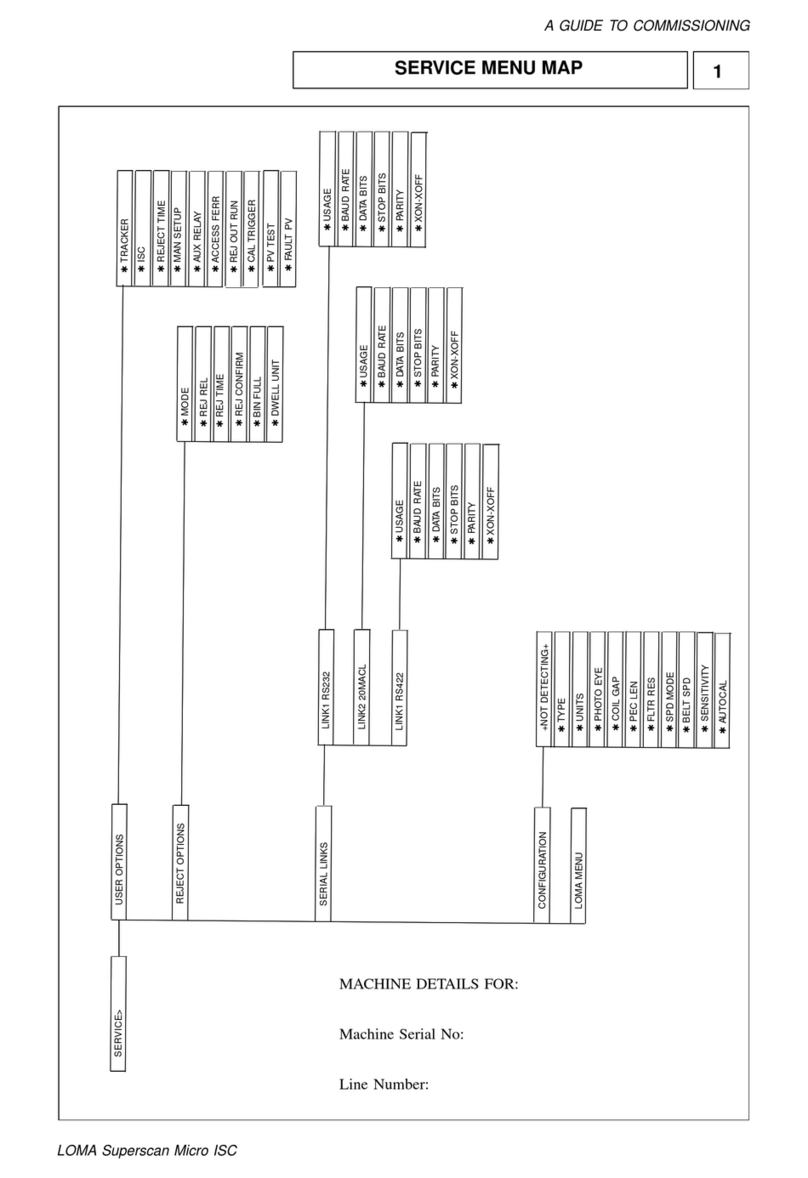
7026 "Configuration and Set up Information" New "ADC setup" menu chain
added to the "Loma menu" for version 1.1 software.
Details of individual ADC set up menus together with how & when to use
them added.
New "Step 6" (ADC set up) added to the "Step by Step" configuration
sequence.
D
6022 Symbols for Run error & System Fault corrected, they were reversed. E
7026 Symbols for Run error & System Fault corrected, they were reversed. E
Hyperlink to the Flash memory Programming Supplement added from
manual front page. E
3000 Loma Gmbh new address added. E
Flash Note on fitting a boot eprom added. E
7026 Serial link 16-way chassis connector wiring amended to suit the new IQ2
serial link loom assembly. F
7026 New IQ2 serial link loom assembly part number added. F
8023 Section added on +/-12v DC protection fuses. Locations added to figure 2. F
9095 Reference to +/-12v Dc protection fuses added to DC rail checks. F
11050 New control & psu board and protection fuse part numbers added to spare
parts list. F
Flash Step 9 re-written to recommend a cold start after flash memory
programming is completed. F
7026 38mm Pharmaceutical aperture size corrected G
8023 Voltage free relay contact information contacts shown statement corrected
to "de-energised". G
3000 Loma France & Germany for service now call Loma bv G
Flash Step 9 re-written to instruct a cold start after flash memory programming is
completed. G
3000 New address & telephone numbers for bv, France & Germany Sales &
Service H
8023 Lethal Hazard. Note added about mesh removal whilst detector is
powered. H
8023 Control board removal instruction 3. Report/log package may be included
with replacement boards. H
8023 Control & PSU Board removal & refitting. Note on replacing with the same
assembly part number added. H
11050 New part numbers added for control boards with report/log package fitted. H
11050 UL & non UL control board & PSU part numbers fitted with reports & logs
package added. H
3000 Telephone numbers for bv, France & Germany Sales & Service J
8023 New PSU cover & main earth ground added J
11050 New parts added, two piece safety cover & watertight glands J
5092 Information added regarding immunity modifications for UHF walkie-talkie
radios. K
Loma Systems
Loma IQ2Service Manual Part No 814119, Issue Level K 19/02/03
Module Amendment Issue
7026 Dual frequency & Auxiliary (Aux.) relay menu positions added K
7026 Catalogue freefall & ferrous in foil coil gaps added K
7026 Details of new trend type tracker added K
8023 Dual frequency information aded K
9095 Dual frequency balance & phase integrity checks added K
11050 Dual frequency board part numbers added K

The Loma Companies & Service Centres
Module 3000 1-1
SALES
UK
Loma Systems Limited, Southwood, Farnborough, Hampshire, GU14 0NY, England
Telephone: 01252 893300 Fax: 01252 513322
E-mail: sales@loma.co.uk
CANADA
Loma Canada Limited, 333 Wyecroft Road, Unit 2, Oakville, Ontario, Canada L6K 2H2.
Telephone: 1-800-387-7987/ 905-842-4581 Fax: 905-842-3460
E-mail: lomacanada@loma.com
NETHERLANDS
Loma Systems BV, Panovenweg 22, 5708 HR, Helmond, Netherlands.
Telephone: +31 (0) 492 573573 Fax: +31 (0) 492 573570
E-mail: info@lomasystems.com
FRANCE
Loma Systems BV, Panovenweg 22, 5708 HR, Helmond, Netherlands.
Telephone: +33 (0) 1 55695777 Fax: +33 (0) 1 55174331
E-mail: info@lomasystems.com
GERMANY
Loma Systems BV, Panovenweg 22, 5708 HR, Helmond, Netherlands.
Telephone: +49 (0) 69 50070357 Fax: +49 (0) 69 50070405
E-mail: info@lomasystems.com
USA & SOUTH AMERICA
Loma International Inc., 283 East Lies Road, Carol Stream, Illinois 60188, USA.
Telephone: 1-630-588-0900 / 1-800-USA-LOMA Fax: 1-630-588-1395
E-mail: sales@loma.com Internet address: www.loma.com

The Loma Companies & Service Centres
Module 3000 1-2
THE LOMA GROUP SERVICE CENTRES
UK
Loma Customer Services, Unit 43 Campus Road, Bradford, West Yorkshire
BD7 1HR
Telephone: 01274 378200 Fax: 01274 729716
E-mail: service@loma.co.uk
BENELUX
Loma Systems BV, Panovenweg 22, 5708 HR, Helmond, Netherlands.
Tel. Service +31 (0) 492 573550
FRANCE
Loma Systems BV, Panovenweg 22, 5708 HR, Helmond, Netherlands.
Tel. Service +33 (0) 1 55695778
GERMANY
Loma Systems BV, Panovenweg 22, 5708 HR, Helmond, Netherlands.
Tel. Service: +49 (0) 69 50070358
USA and SOUTH AMERICA
Loma International Inc., 283 East Lies Road, Carol Stream, Illinois 60188, USA.
Telephone: 1-800-USA-LOMA / 1-630-588-0900 Fax: 1-630-588-1396
CANADA
Loma Canada Limited, 333 Wyecroft Road, Unit 2, Oakville, Ontario, Canada L6K 2H2
Telephone: 1-800-387-7987 / 905- 842-4581 Fax: 905-842-3460
REST OF WORLD
Loma Customer Services Dept., Unit 43 Campus Road, Bradford, West Yorkshire
BD7 1HR, UK
Telephone: (44) 01274 378200 Fax: (44) 01274 729716

Cautionary Advice
Module 4004 2-1
CAUTIONARY ADVICE
CONTENTS
Safety Warnings .....................................................................................................................2
Lethal Hazard Electrical Supplies.........................................................................................2
Working on Equipment..........................................................................................................2
Lifting Equipment...................................................................................................................2
Moving a Search Head...........................................................................................................2
Using a Crane .........................................................................................................................3
Using a Fork Lift Truck ..........................................................................................................3
Dealing with Fire.....................................................................................................................3

Cautionary Advice
Module 4004 2-2
Safety Warnings
Listed below are safety warnings that are used throughout this manual. It is
strongly recommended that personnel who are, or will be, responsible for
maintaining or operating the equipment described in this manual should read
and understand these warnings.
1. LETHAL HAZARD – ELECTRICAL SUPPLIES. A current of 100 milli-amps
passing through the body for one second can kill. This can occur at voltages as
low as 35V ac or 50V dc. The equipment described in this manual uses
electrical power which can be lethal. Unless absolutely necessary, cleaning,
inspection and maintenance must not be carried out without first isolating the
equipment from all electrical supplies.
2. WORKING ON EQUIPMENT. If it is essential to work on the equipment with
electrical power connected, the work must be undertaken only by qualified
personnel who are fully aware of the danger involved and who have taken
adequate safety precautions to avoid contact with dangerous voltages
3. LIFTING EQUIPMENT. Use only the correct slings and lifting tackle to move
heavy items of equipment described in this manual. Inspect all slings and lifting
tackle prior to lifting the equipment to ensure that:
(a) The safe working load will not be exceeded.
(b) There are no frayed or broken strands.
(c) Hooks, rings, etc. are not damaged.
WARNING
MOVING A SEARCH HEAD. Some metal detector search heads are
extremely heavy. Care must be taken when moving such a head to ensure
that it can not fall or topple over. This could result in death or severe
injury to an individual and/or severe damage to the head.
Depending on the size and weight of a head, either a crane or a fork-lift
truck will be required to lift and move it into the final location.

Cautionary Advice
Module 4004 2-3
Using a Crane
(a) Position the straps beneath the head so that it can not tilt when lifted. Attach
the straps to the crane.
(b) Lift the head and carefully move it to the required location.
(c) Lower the head and remove the straps.
Using a Fork Lift Truck
(a) Position the forks beneath the head so that it cannot tilt. Raise the lift
sufficiently to lift the head clear of the ground and any obstacles.
(b) Carefully move the head to the required location.
(c) Lower the forks and withdraw them from the head.
Dealing With Fire
4. In the unlikely event of fire occurring in an item of equipment manufactured by
Loma Engineering, it is important that a fire extinguisher containing the correct
type of extinguishing material is used. Fire on electrical equipment must be
extinguished using a dry powder extinguisher (Blue in the United Kingdom).

Product Description and Environment
Module 5092 3-1
PRODUCT DESCRIPTION AND ENVIRONMENT
CONTENTS
Search Head and Control Unit Technical Specification ......................................................2
Electrical Supplies...................................................................................................................3
Spurious Triggering ................................................................................................................3
EMC Interference .....................................................................................................................4
Radio Frequency Interference................................................................................................5

Product Description and Environment
Module 5092 3-2
Search Head and Control Unit
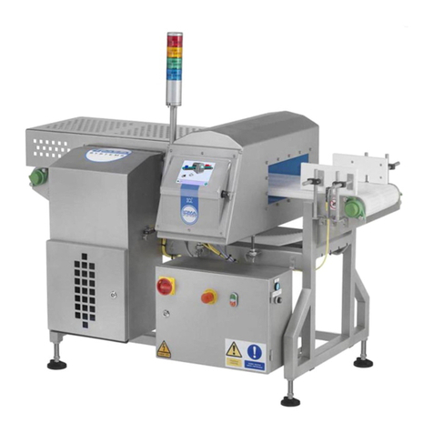
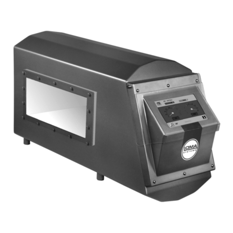
This section describes Loma IQ metal detector search head and control unit.
Technical Specification
Search Head.............................................................................................................Loma IQ2
Case Material.........................................................................Stainless steel 304L, fabricated
Case Finish ........................................................................................................Bead blasted
Environmental Protection.........................................................................Dust and waterproof
Control Unit ..............................................................................................................Loma IQ2
Mounting ...................................................................................On search head or remote
Voltage Standard Universal Input .........................................85-264V, single phase, 50/60Hz
Operating Temperature........................................................-10°C to 40°C (+14°F to +104°F)
Relative Humidity...........................80% up to 31°C (86°F) reducing to 50% @ 40°C (104°F)
The metal detector search head and control unit has been designed for use with
continuous motion conveyor systems, pipeline, pharmaceutical and freefall
metal detectors.
As standard, the control unit is secured at the end of the search head. This unit
enables suitably trained personnel to set up, change, calibrate, and obtain
results from the system through a menu-driven user interface. The control board
can be fitted with an optional board providing the following serial link options – 1
x RS232 (hardware hand shaking). 1 x 20ma current loop, and 1 x RS422 (both
software handshaking). See the "Serial link" on page 25 section later in this
manual.
The control board can also be fitted with an optional external sensor board
enabling the following functions to be supported - Product registration photoeye.
Reject device actuation or confirmation of a rejected item entering a reject
collection container, photoeye or a movement sensor can achieve this. Reject
bin full sensing photoeye. Variable speed sensing using a shaft encoder.
Remote calibration command uses a simple switch.

Product Description and Environment
Module 5092 3-3
The control board can also be fitted with an optional reports package supporting
an on board real time clock and date function together with a range of standard
reports and logs as shown in the equipment user manuals.
The control unit is compatible with the following Loma communication packages.
LomaNet - Optional node, serial link board, reports and logs package and
external connectors required.
LomaLink - Optional serial link board, reports and logs package and external
connectors required.
Electrical Supplies
Electrical supplies are connected to the control unit directly into the bottom of
the control unit via waterproof glands.
Control unit connection details can be found in the - “Connecting to a Power
Source” on page 12 in the “Maintenance” section of this manual.
For specific wiring connection information including any conveyor wiring
diagrams, please refer to the “Wiring Diagrams” package in your Customised
User Manual.
Spurious Triggering
The Loma range of Metal Detectors is the product of many years' experience
and development. They are inherently reliable. Provided a detector is set up as
described in the setting up procedure, it is unlikely that any problem lies within
the head assembly or control unit.
Sources of spurious or false triggering can be:
•Operator rings or watches.
•Belt contamination even by small particles of rust.
•Remember to clean the underside as well as the top surfaces you
can see.
•Metallic belt clips even if plastic coated.
•Metallic guide rails particularly into the metal free area.

Product Description and Environment
Module 5092 3-4
•A conveyor bolted together rather than welded (potential for Eddy
Current Loops).
•Metallic inks or labels.
•Metallic frames to infeed or outfeed guards.
•Low grade or reclaimed cardboard packing materials that often
contain metallised paper or foil.
•Particles of metal under the skid plate.
EMC Interference
All Loma equipment has been designed to operate under factory conditions, and has been tested
to recognised international standards for Electro Magnetic Compatibility (EMC).
However, if your equipment is affected by unexplained false rejections that cannot be accounted
for by any of the suggestions listed under Spurious Triggering, the equipment may be affected by
excessive electrical noise via its supply or airborne (radiated) sources.
Guidance on EMC Considerations when installing your equipment is given in your User Manual.
However, as a first step to eliminating EMC interference, the following considerations should be
checked.
Electrical supply considerations
The unit should have its own dedicated supply, unless the line supply was
known to be clean. The earth should be robust, of low impedance and noise
free.
Any dedicated supply line should run in its own conduit/trunking away from other
noisy supplies.
The input voltage should not be subject to voltage fluctuations outside the limits
(BS EN 61000-6-2):
1. Minus 15% to plus 10% of the nominal supply voltage (230V or 110V).
2. Zero voltage for more than 20mS.
3. 50% of nominal voltage for more than 40mS.
4. 80% of nominal voltage for more than 100mS.
5. Operation outside these limits may cause loss of function until the supply condition
recovers to within limits.

Product Description and Environment
Module 5092 3-5
Other EMC Considerations
Any external sensor connected to the Metal Detector should be in screened
cable, grounded at the point of entry into the metal detector control box and kept
free from sources of electrical noise (e.g. mains supplies for large electrical
machines).
The metal detector is a highly sensitive RF measuring device, which is well
screened from outside interference and has excellent electronic discrimination
against unwanted electromagnetic fields. However, due to it’s sensitivity it is
possible that other devices that emit high levels of RF noise at the operating
frequency of the detector may cause interference, thereby degrading the
performance of the detector.
NOTE
These guidelines are based on the PPMA EMC Code of Practice, which
should be referred to if in doubt about any aspect of making external
electrical connections to the detector.
Radio Frequency Interference
A metal detector is, essentially, a Radio Frequency (RF) receiver. As such it is
sensitive to RF noise in the general vicinity of the detector location. While those
frequencies not close to the operating frequency of the detector will usually be filtered
out (this includes most ‘walkie talkie’ frequencies, unless the transmitter is held very
close to the detector aperture). It is not uncommon for the control frequency (or a
multiple of it), used in modern speed controllers, to cause interference.
To reduce the risks of such interference causing false rejects or other symptoms of
undesirable operation at the metal detector, the following recommendations should be
followed:
Always route speed controller input and output wiring away from the metal detector
area. NEVER put speed controller wiring in the same conduit or on the same supply
as the metal detector wiring.
Run speed controller wiring in the general vicinity of the metal detector in a rigid steel
conduit or use other techniques to ensure 100% screening of the cable. Always follow
the speed controller manufacturer’s instructions for installation, wiring, screening and
grounding.
In addition to following these guidelines, most speed controller manufacturers can
supply input and output filters which can be fitted to the field wiring to dramatically
reduce RF emissions if necessary.

Product Description and Environment
Module 5092 3-6
All Loma metal detectors are designed, and tested, to meet the requirements of the
FCC and the new stringent European regulations for RF emissions. Both in terms of
not emitting excessive or being unduly affected by emissions from other equipment
whose emissions also meet the standards?
This approach allows Loma to offer stable operation even in RF noisy environments,
provided the other equipment is to the same standards and the field wiring is suitably
‘hard’.
Hand Held Walkie-Talkie Radios
Interference from UHF walkie-talkie radios operating in the carrier frequency range of
403 - 470 MHz have been increasingly problematic because they can severely interfere
with general-purpose metal detectors of all types and operating frequencies.
The interference occurs whenever the talk button is pressed or released resulting in,
on occasion, very high signal readings often in the thousands leading to false triggering
of the detector.
This effect can be eliminated by the addition of extra screening with connection filtering
for the search headboard.
The suppression system was made available as standard build on Freefall detectors
for the Americas and optional elsewhere from about March 2003.
If interference is experienced from this type of radio then contact your local service
office with details of the affected detector/s. Due to the physical size of the
modification it cannot be ordered or retrofitted for Pipeline or Pharmaceutical
detectors.

Fault and Error Diagnosis
Module 6022 4-1
FAULT AND ERROR DIAGNOSIS
CONTENTS
Cold Start ................................................................................................................................2
Run Errors...............................................................................................................................3
System Faults .........................................................................................................................4
Diagnostic Errors ...................................................................................................................6
LomaLink Diagnostic Errors .................................................................................................6

Fault and Error Diagnosis
Module 6022 4-2
Cold start
Other than that initiated by the use of JP6 on the control board, will not normally occur
under normal operating conditions. However, there may be circumstances such as a
faulty power supply or a noisy main supply that may cause the control unit to lose its
memory. Should this occur then the display would show the warning message +Not
detecting+ located at the top of the Configuration menu.
Message Cause Solution
+Not detecting+ Spurious cold start 1. Establish and repair the
cause of the problem for
example carry out checks
on the power supply DC
rails as described in “DC
Rails” on page 7 section in
the “Functional Testing”
section of this manual
2. Re-commission the
control unit as described in
the “Configuration” on page 4
section of this manual
To perform a "cold start" go to “Hardware Cold Starting” on page 8 in the “Maintenance”
section of this manual.

Fault and Error Diagnosis
Module 6022 4-3
Run Errors
Are classified as non-fatal but requires an operator's attention. When an error is
generated the attention relay operates and subsequently any remote device connected
to it. In addition the Run Error LED !
!!
!on the User Interface illuminates. If your
detector is fitted with the Reports/Logs package the errors can be accessed in the Run
Error menu "View errors". All errors are described as either passive (PSV), active
(ACT) or as an event (EVT) the date & time accompany errors.
Message Cause Solution LomaLink
Error No.
PV test
prompt A programmed PVS test
prompt has occurred. 1. Complete a PV Test. 22
Pec blocked PEC has remained blocked for
5 consecutive pack lengths.
Product registration photoeye
only.
1. Check the PEC for
blockage.
2. Check PEC is
working.
3. Check pack flow
length entry is adequate,
ensuring an allowance is
made for pack skewing.
4. Ensure correct belt
speed is entered.
23
Neg delay
exten Reject dwell time setting
problem. Variable speed
systems only.
1. Check reject delay
and dwell time settings. 24
Speed too fast Belt speed is greater than the
upper limit for existing filter
resistors, coil gap and belt
speed. Variable speed systems
only.
1. Decrease belt speed.
2. Change filter resistors
to lower value. Refer to
“Belt Speed” on page 14 in
the “Configuration &
Setup” section of this
manual
25
Speed too
slow Belt speed is less than the
lower limit for existing filter
resistors, coil gap and belt
speed. Variable speed
systems.
1. Increase belt speed.
2. Change filter resistors
to higher value. Refer to
“Belt Speed” on page 14 in
the “Configuration &
Setup” section of this
manual
26
Reject too
close The reject system is still
counting out the dwell for a
reject when the next pack to be
rejected comes along
1. Reduced the reject
dwell time.
2. Improve the pack
pitch.
3. If the reject is a
retracting band or
lift/drop flap, change the
reject mode to pulse
extension.
27
Reject
disabled The reject relay has been
disabled. 1. Enable the reject
relay using the Reject
enable command.
29
Note: PEC = Photo Electric Cell or Photoeye. PVS = Performance Validation System.

Fault and Error Diagnosis
Module 6022 4-4
System Faults
Are classified as fatal and require immediate action. When an error is generated the
fault relay operates, permanently operating the reject device and/or stopping the
conveyor transport. In addition the Fault Relay LED "
""
"on the User Interface
illuminates. If your detector is fitted with the Reports/Logs package the faults can be
accessed in the System Fault menu "View faults". All faults are described as either
passive (PSV), active (ACT) or as an event (EVT) the date & time accompany errors.
Message Cause Solution
Osgo out of spec The search head transmitter has
failed or its value is less than
10v.
1. Check the head cable is
properly seated in PL1 on the
control board.
2. Check OSGO DC voltage as
described in “OSGO” on page 5 in
the “Functional Testing” section
of this manual.
5v out of spec 5v rail is less than 4.75v 1. Check 5v rail as described in
“DC Rails” on page 7 the
“Functional Testing” section of
this manual.
+12v out of spec +12v rail is less than 11.40v 1. Check +12v rail as described
in “DC Rails” on page 7 in the
“Functional Testing” section of
this manual.
+Powered up+ Logged every time the system is
powered up. No action required.
Verdict too late A pack has arrived at the reject
point before the detector has
sent a reject decision.
1. Increase the reject delay time.
2. If in PEC Mode, reduce the
pack length.
Verdict mismatch The system has more reject
verdicts than packs passed. 1. Power machine off and on.
Rej confirm fail The reject system has attempted
to reject a pack but could not
confirm that the pack was
removed from the line, within the
specified time.
If the pack has been correctly
rejected:
1. Check the Reject confirm
sensor is working.
2. Check the Reject confirm
timing parameters are correct.
Rej con wind fail The reject confirmation system
has received two packs in one
reject confirm window.
1. If 2 packs were supposed to
be rejected than reduce the
Reject confirm window.
2. Reduce the Reject dwell time.

Fault and Error Diagnosis
Module 6022 4-5
Message Cause Solution
Bin full The reject bin full sensor has
detected that the bin is full. If the bin is not full:
1. Check the Bin full sensor is
working correctly.
2. Check the Bin full sensor is
wired in the correct sense.
Link corrupted Data corruption has occurred
between the detector and
LomaLink PC/other controlling
device. The operation of the
detector is unaffected.
1. Check cabling and link
connectors from remote device.
2. Check LomaLink PC/ other
controlling device for reported
errors.
Link failure A break in communication
between the detector and
LomaLink PC/other controlling
device. The operation of the
detector is unaffected.
1. Check cabling and link
connectors from remote device.
2. Check connections between
the detector and LomaLink
PC/other controlling device for
loose or broken
wiring/connectors
PV test timeout A prompted for PVS test has
either not been done or
completed with the window time
set.
1. Clear system fault.
2. Perform a PVS Test.
Note: Osgo = OScillator GOing.
PVS = Performance Validation System.
Other manuals for IQ2
1
Table of contents
Other Loma Metal Detector manuals