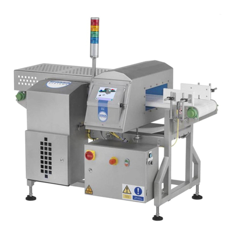
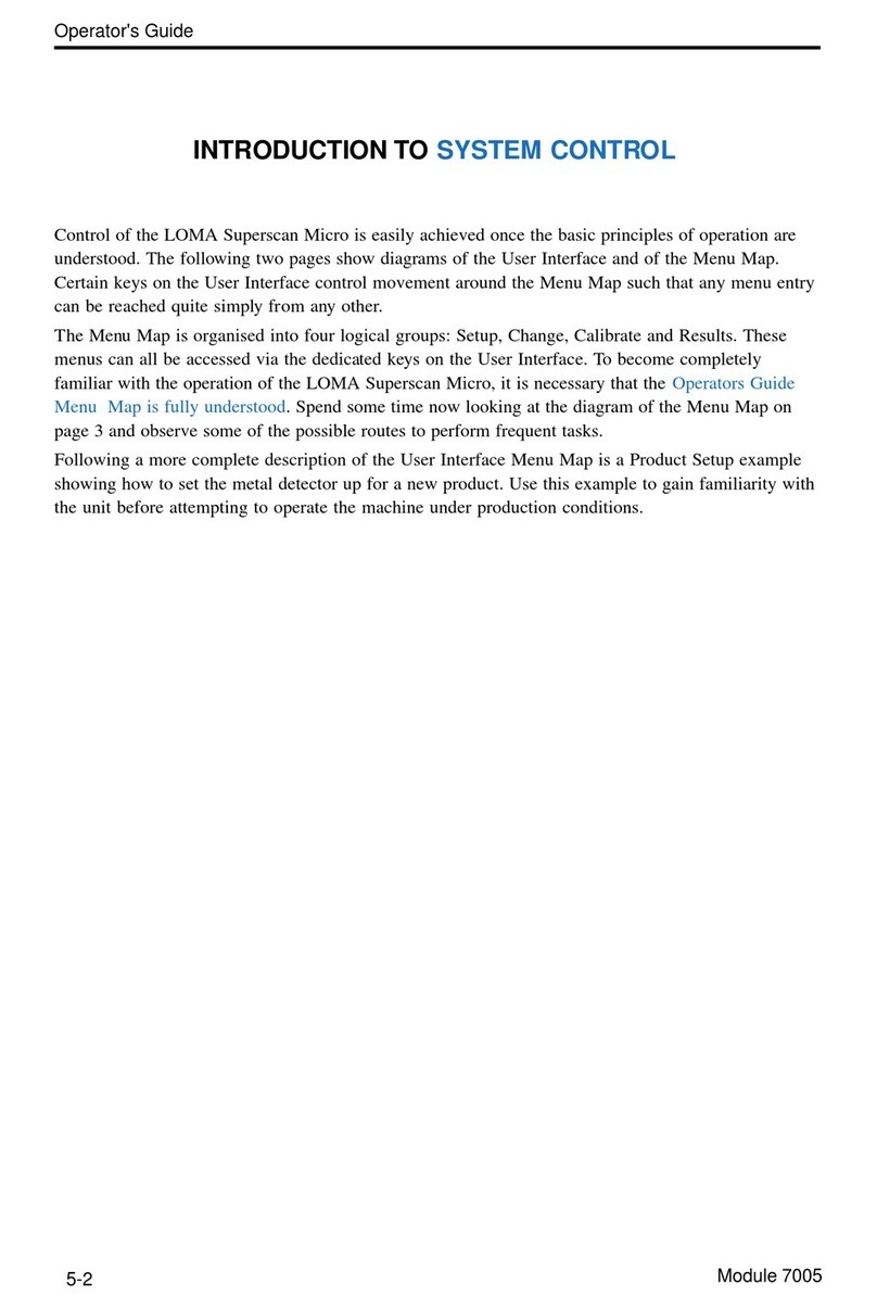
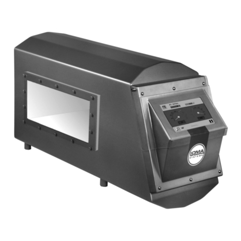
Loma Superscan Micro ISC User manual

A GUIDE TO COMMISSIONING
1
LOMA Superscan Micro ISC
SERVICE MENU MAP
MACHINE DETAILS FOR:
Machine Serial No:
Line Number:
USER OPTIONS
SERVICE> ✱TRACKER
✱ISC
✱REJECT TIME
✱MAN SETUP
✱AUX RELAY
✱ ACCESS FERR
✱REJ OUT RUN
✱CAL TRIGGER
✱MODE
✱REJ REL
✱REJ CONFIRM
✱BIN FULL
✱DWELL UNIT
REJECT OPTIONS
✱REJ TIME
✱USAGE
✱ BAUD RATE
✱DATA BITS
✱STOP BITS
✱ PARITY
✱XON-XOFF
✱ BAUD RATE
✱USAGE
✱DATA BITS
✱STOP BITS
✱ PARITY
✱XON-XOFF
✱ BAUD RATE
✱DATA BITS
✱STOP BITS
✱ PARITY
✱XON-XOFF
✱USAGE
CONFIGURATION
LOMA MENU
+NOT DETECTING+
SERIAL LINKS LINK1 RS232
LINK2 20MACL
LINK1 RS422
✱ TYPE
✱UNITS
✱PHOTO EYE
✱ COIL GAP
✱ FLTR RES
✱SPD MODE
✱ BELT SPD
✱SENSITIVITY
✱ AUTOCAL
✱PV TEST
✱FAULT PV
✱PEC LEN

A GUIDE TO COMMISSIONING
2
LOMA Superscan Micro ISC

A GUIDE TO COMMISSIONING
3
LOMA Superscan Micro ISC
INTRODUCTION
When the detector is switched on for the first time it needs to be configured for the end application.
Wherever possible this will be carried out by Loma before the unit is dispatched from our factory, or
alternatively, by a LOMA Service Engineer during a commissioning visit. Primarily, this information
is required to optimise machine performance for the application, and to enable certain features that
the user may require.
There are circumstances, however, where it may be necessary for the end user to carry out the
commissioning procedure for the control unit himself. Typically, this would occur when LOMA do
not have enough information about the end application, such as the belt speed or reject details, to
fully configure the machine. There are, in addition, other instances such as performing a software
update, moving the detector to a different application, replacing a control card, etc.. By following
through the step by step configuration guide the unit can easily be set up from scratch as required.
Alternatively, if only small changes are required to the configuration of the machine, then the menu
entries within the Service menu can individually be adjusted.
STEP BY STEP CONFIGURATION
At the start of this section is a menu map for the Service menu upon which configuration details for
the machine can be recorded. We suggest that you fill this in when you configure the system, so that if
you ever need to repeat the exercise all the information will be ready to hand.
Step One
If the unit is not already at the top of the Configuration menu, displaying the +NOT DETECTING+
warning message, go to this menu position now. If you do not know how to do this, press the
following key sequence:
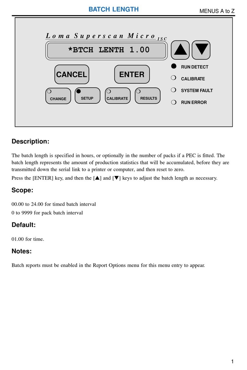
1Press the [SETUP] key once.
2Press the [▼] key until the display shows “SERVICE”.
3Press the [ENTER] key once.
4Press the [▲] key until the password shows “21”.
5Press the [ENTER] key once. The display should now show “USER OPTIONS”.
6Press the down key three times, so that the display shows “CONFIGURATION”.
7Press the [ENTER] key once.
8The display should now be showing “+NOT DETECTING+”.
Moving around the menu is explained on page 6 of the Operators Guide.
Step Two
The correct parameters must now be entered into the configuration menu. To gain access to the
COMMISSIONING GUIDE

A GUIDE TO COMMISSIONING
4
LOMA Superscan Micro ISC
parameters use the [▲] and [▼] keys to move to the parameter (ie. to move up or down the
configuration menu), and then press the [ENTER] key so that the [▲] and [▼] keys will alter the
parameter (notice how the “✱” moves to the right when the display is in parameter edit mode). Once
the correct parameter has been entered, simply press the [ENTER] key again to save the value.
Move down through the Configuration menu now, making adjustments as required by your
application:
TYPE: Select either CONVEYOR, FREEFALL, PIPELINE or PHARM depending
upon your system configuration.
UNITS: Select METRIC or IMPERIAL as preferred.
PHOTO EYE: Select YES if a photo eye has been wired to the control board.
COIL GAP: Enter the Coil Gap as shown on the machine details plate (inside control
box), or by reference to Table 1 below.
PEC LEN: If the entry Photo Eye = Yes has been made, this entry will appear, and a
value must be entered. The PEC Length is the distance from the centre line
of the photo eye to the leading face of the detector plus the Rx distance
(again shown on the machine details plate).
FLTR RES: Enter the filter resistor value as fitted on the main control board. Brown-
plastic plug in module. Remove top to read value.
SPD MODE: Select FIXED, unless your system is vari-speed or free-running. For
variable speed systems select VARI, and for free-running FRUN. If in
doubt about the required selection, refer to the Principles of Operation
section.
BELT SPD: If fixed speed mode has been selected this entry will appear, in which case
enter the belt speed.
CTB CNST: If variable speed mode has been selected this entry will appear, in which
case enter the CTB constant (the CTB constant is the number of pulses per
metre/foot of belt travel from the shaft encoder in vari-speed applications -
see note on vari-speed at the end of this section).
SENSITIVITY: Select the required level of sensitivity to be adopted during auto-
calibration. The higher the setting the more sensitive the detector, but the
more prone it will be to false rejects if the product effect varies (phase
dispersion). We recommend HI for most applications.
AUTOCAL: Select the desired auto-calibration period:
Photo Eye No Photo Eye
Short 8 packs 20 seconds
Long 20 packs 1 minute
Extra Long n/a 2 minutes
Short is recommended for most applications, provided that at least eight
packs can be passed during a calibration cycle.
COMMISSIONING GUIDE
A GUIDE TO COMMISSIONING
5
LOMA Superscan Micro ISC
Head Type Coil Gap
Standard, full size, Rectangular Heads 0.8 x Minimum Aperture Dimension
3" to flow Freefall Heads 48mm
5" to flow (and "CF") Freefall Heads 76mm
Standard Pipeline Heads 0.75 x Aperture Dimension
6000 Series Combo Heads 76mm
3000 Series Combo Heads 0.8 x Minimum Aperture Dimension
Table1
Computation of coil gap by head type and minimum aperture dimension
Step Three
The detector must now be set up for the desired user options. Until you are completely familiar with
the operation of the detector, it is recommended that all the options are left at their default values.
Press the [CANCEL] key once to move out of the Configuration menu, and then the [▲] key enough
times so that the display shows “USER OPTIONS”. Press the [ENTER] key once to move into the
User Options menu, and then set up your options are desired:
TRACKER: This option will only appear if photo-eye operation has been selected in the
configuration menu. Turn this ON or OFF as required (see the A-Z section
for an explanation).
ISC: Turn this ON or OFF as required. This option is explained in the A-Z and
Principles of Operation sections.
REJECT TIME: Leave this at the default option of ON to enable access to the reject timing
information in the Product Setup menu. Only set this to OFF once the reject
time has been correctly set, and you with to deny line operators access to it.
MAN SETUP: Turn this ON or OFF as required. This option is explained in the A-Z
section.
AUX RELAY: Turn this to ERROR or RUN as required. Refer to User Options in the A-Z
section for more information.
ACCESS FERR: This entry must be set to yes, in order that a ferrite tune can be performed -
see later.
REJ OUT RUN: Turn this ON or OFF as required. Refer to User Options in the A-Z section
for more information.
CAL TRIGGER: Turn this ON or OFF as required. Refer to User Options in the A-Z section
for more information.
*PV TEST: Set to YES or NO as required. YES will enable the Performance Validation
system. Refer to the A-Z section and the Performance Validation system
section in Principles of operation for more information.
*FAULT PV: Set to YES or NO as required. YES will cause the fault relay to operate if a
Performance Validation system test is not actioned or completed in the time
allowed.
Exit the User Options menu by pressing the [CANCEL] key once.
COMMISSIONING GUIDE

A GUIDE TO COMMISSIONING
6
LOMA Superscan Micro ISC
Step Four
Move to the Reject Options menu and set up the detector as required for your application. Please refer
to the Reject Options menu in the A-Z section for more information.
Press the [CANCEL] key once to exit the Reject Options menu.
Step Five
If you are using any of the serial links, then you will need to set up the serial links as described in the
Serial Link menu in the A-Z section.
Step Six
The machine will now be looking for metal in your product, although the sensitivity will not be fully
optimised as the detector has not yet been calibrated for the product. Before any products can be
calibrated, it will be necessary to perform a ferrite tune in order to minimise the effects of vibration
when running products with no product effect (see section on Principles of Operation for more
information).
Perform a ferrite tune as follows:
• Change to product F (the ACCESS FERR entry in the User Options menu must be set to yes in
order to do this). To do this press the [CHANGE] key, the down key until “FERRITE F” is
shown, and finally the [ENTER] key.
• Perform a Full Calibration whilst moving the end of the ferrite wand with the sample in in and
out of the search head. Be careful not to put your hand in or get any watches/rings near the search
head. On systems fitted with a PEC block the PEC to register that packs are present. To do this
press the CAL key once, followed by the [▼] key once and then the [ENTER] key once.
• Now go back to the User Options menu and disable the access to product F (ACCESS FERR
NO).
The control unit is now fully commissioned for your application.
COMMISSIONING GUIDE

A GUIDE TO COMMISSIONING
7
LOMA Superscan Micro ISC
VARIABLE SPEED SYSTEMS
On systems employing variable speed conveyors, special hardware is required to drive the CTB
(conveyor time base) input on the micro control card. Conveyor systems supplied by LOMA will
already have this hardware fitted and commissioned, but on head only sales the following information
should be observed when using vari-speed.
Overview
In order for the reject timing to work correctly, it must be supplied with information about how far the
contaminant has travelled between the head and point of reject. This is achieved via a shaft encoder
which supplies pulses to the CTB input of the micro control board - refer to the supplied wiring
diagrams.
The delay information, which is entered in the Product Setup menu, then counts the CTB pulses out to
time the contaminated product to the reject point. For this reason the delay is measured in distance,
and should be set at the fastest conveyor speed in order for the reject device to actuate in time. The
dwell, on the other hand, should be set at the slowest belt speed to guarantee accurate rejection at all
speeds. The dwell can be in units of time or distance depending upon the type of reject device.
CTB Constant
This parameter is the number of pulses per metre/foot of belt travel. For systems fitted with a photo-
eye it can be set between 1 and 999 pulses per metre/foot, whereas for non photo-eye systems it can
be set between 1000/coil_gap and 999 pulses per metre/foot. The shaft encoder for the system should
be chosen so that it gives sufficient resolution for accurate rejection, but not so much that the CTB
rate will exceed a frequency of 100Hz at the maximum belt speed. An absolute minimum of 4 pulses
must occur over the coil gap distance. The coil gap distance can be found on the machine details
plate (inside control box).
Vari-Speed Errors
Because the detector can only work within a pre-determined speed range it is possible for belt speed
to move outside the limit of reliable operation of the machine. In these cases, speed logging problems
can be turned on in the configuration menu which will generate either SPEED TOO SLOW or SPEED
TOO FAST run errors.
COMMISSIONING GUIDE
A GUIDE TO COMMISSIONING
8
LOMA Superscan Micro ISC
Other manuals for Superscan Micro ISC
1
Table of contents
Other Loma Metal Detector manuals