Longshine LCS-883R-SW802 User manual

CE Declaration of conformity
This equipment complies with the requirements relating to electromagnetic compatibility, EN
55022 classAfor ITE, the essential protection requirements of Council Directive 89/336/EEC on
the approximation of the laws of the Member States relating to electromagnetic compatibility.
FCC Warning
This equipment has been tested and found to comply with the limits for a ClassA digital device,
pursuant to Part 15 of the FCC Rules. These limitations are designed to provide reasonable
protection against harmful interference in a residential installation. This equipment generates, uses
and can radiate radio frequency energy and, if no installed and used in accordance with the
instructions, may cause harmful interference to radio communications. However, there is no
guarantee that interference will not occur in a particular installation. If this equipment does cause
harmful interference to radio or television reception, which can be determined by turning the
equipment off and on, the user is encouraged to try to correct the interference by one or more of
the following measures:
Reorient or relocate the receiving antenna.
Increase the separation between the equipment and receiver.
Connect the equipment into a different outlet from that the receiver is connected.
Consult your local distributors or an experienced radio/TV technician for help.
Shielded interface cables must be used in order to comply with emission limits.
Changes or modifications to the equipment, which are not approved by the party responsible for
compliance could affect the user’s authority to operate the equipment.
Copyright © 2001All Rights Reserved.
Company has an on-going policy of upgrading its products and it may be possible that information
in this document is not up-to-date. Please check with your local distributors for the latest
information. No part of this document can be copied or reproduced in any form without written
consent from the company.
Trademarks:
All trade names and trademarks are the properties of their respective companies.
1

Table of Contents
1. Unpacking Information
2. Introduction To 8+2 Gigabit NWay Switch
2.1 General Description
2.2 Key Features
2.3 The Front Panel
2.3.1 System LEDs
2.3.1.1 Power LED
2.3.2 Port LEDs
2.3.2.1 10/100Mbps Ports LED
2.3.2.2 Gigabit Ports LEDs
2.3.3 Console Port
2.4 The Rear Panel
2.4.1 Power Connecting
3. Installing And Using 8+2 Gigabit NWay Switch
3.1 Installing the 8+2 Gigabit NWay Switch
3.1.1 Desktop Installation
3.1.2 Rack-Mount Installation
3.1.3 Installing Network Cables
3.1.3.1 Station Connection with Twisted-Pair Cable
3.1.3.2 Switch to Switch Connections with Twisted-Pair Cable
3.1.3.3 NetworkApplication
4. Switching Operation
4.1 MACAddress Table & Learning
4.2 Filtering and Forwarding
4.3 Store and Forward
5. Console Program
6. Product Specifications
2

1. Unpacking Information
Thank you for purchasing the 8+2 Gigabit NWay Switch. Before you start, please check all
the contents of this package. If there is anything missing, please contact with your local
agent.
The product package should include the following:
1. One 8+2 Gigabit NWay Switch
2. One power cord
3. Rack-mount brackets and screws (Optional)
4. User’s Manual
3

2. Introduction To 8+2 Gigabit NWay Switch
2.1 General Description
The device is a powerful, high-performance 8+2 10/100/1000Mbps Fast Ethernet and
Gigabit switch, with eight 10/100Mbps ports and two 1000Mbps ports.All ports support auto
MDI-X function and auto-negotiation operation (NWay), which means the switch could
automatically negotiate with the connected partners on the network speed and duplex mode.
The Gigabit copper switching ports are ideal for micro-segmenting large networks into
smaller, connected subnets for improved performance, enabling the bandwidth demanding
multimedia and imaging applications. The Gigabit ports also provide the fat pipe to the
server or backbone connection for boosting the total system performance.
Moreover, the 10/100/1000Mbps auto-sensing ability provides an easy way to migrate
between 10Mbps, 100Mbps or 1000Mbps on networks with no pain. Compared to the
shared 10/100/1000Mbps networks, the switch delivers a dedicated 10/100/1000Mbps
connection to every attached client with no bandwidth congestion issue.
Store-and-forward switching mode promises the low latency plus eliminates all the network
errors, including runt and CRC error packets. To work under full-duplex mode, transmission
and reception of the frames can occur simultaneously without causing collisions as well as
double the network bandwidth.
The switch is plug-n-play without any software to configure and also fully compliant with all
kinds of network protocols. Moreover, the rich diagnostic LEDs on the front-panel can
provide the operating status of individual port and whole system.
For network connection:
The switch can use the following types of cabling:
10BASE-T: Category 3, 4 or 5 UTP/STP
100BASE-TX: Category 5 UTP/STP
1000BASE-T: Category 5 UTP/STP
Category 5 cable is preferred to use with this product in structured wiring
environments. This will ensure correct operation of all ports at 10Mbps, 100Mbps or
1000Mbps.
4

2.2 Key Features
The switch provides the following key features:
Complies with 10BASE-T specifications of the IEEE802.3 standard
Complies with 100BASE-TX specifications of IEEE802.3u standard
Complies with 1000BASE-T specifications of IEEE802.3ab standard
Eight RJ-45 ports for 100BASE-TX/10BASE-T connectivity
Two RJ-45 ports for 1000BASE-T/100BASE-TX/10BASE-T connectivity
One RS-232 console port for basic management
Supports NWay protocol for speed (10/100Mbps)and duplex mode (Half/Full) auto-detection
on 10/100Mbps ports
Supports NWay protocol for speed (10/100/1000Mbps) and duplex mode (Full only)
auto-detection on Gigabit ports
Supports auto MDI-X function on all ports
Supports up to 10 groups of port-base VLAN or 802.1q VLAN
Supports up to 4 groups of port trunking function
Wire-speed packet filtering and forwarding rate
Store-and-forward architecture filters fragment & CRC error packets
Supports 6KBytes MAC address entries in whole system
256KBytes buffer memory
Desk Top design; 19” rack-mountable (with optional rack-mount brackets)
Supports extensive LED indicators for network diagnostics
Internal universal switching power supply (100-240VAC / 50-60Hz)
FCC ClassA, CE
5

2.3 The Front Panel
The front panel of the switch is shown as below.
The auto-negotiation feature of the switch allows each port of the device running at one of
the following operation modes:
Port Speed Duplex Mode
Half-duplex100 Mbps Full-duplex
Half-duplex
10/100 Mbps
10 Mbps Full-duplex
1000 Mbps Full-duplex
100 Mbps Full-duplex
1000 Mbps
10 Mbps Full-duplex
Each port supports auto MDI-X capability, that is the port could connect either the PC or hub
without any cable adjustment.
Warning: The RJ-45 ports are shielded data sockets. They cannot be used as telephone
sockets. Only RJ-45 plugs are allowed to connect these sockets
6
.

LEDs definition
The rich diagnostic LEDs on the front-panel can provide the operating status of individual
port and whole system. The following table is a summary for LEDs definition.
Type LED Status Operation
Steady Green Power is onSystem Power
Off Power is off
Steady Green Connected as 100Mbps100M
Off Connected as 10Mbps
Steady Green The port is connected
Blinking Green There is traffic transverses the port
10/100 Mbps Port
Link/Act
Off No connection
Steady Green Connected as 1000Mbps1000M
Off Not connected as 1000Mbps
Steady Green Connected as 100Mbps100M
Off Not connected as 100Mbps
Steady Green Connected as 10Mbps10M
Off Not connected as 10Mbps
Steady Green The port is connected
Blinking Green There is traffic transverses the port
1000 Mbps Port
Link/Act
Off No connection
2.3.1 System LEDs
System LED indicators are located on the front panel for showing the operating
status of the whole device.
2.3.1.1 Power LED
This indicator lights green when the switch is receiving power; otherwise, it is
off.
7

2.3.2 Port LEDs
Port LED indicators are located on the front panel for showing the operating status of
each port.
2.3.2.1 10/100Mbps port LED
Every port has a 100M LED. Steady green indicates that the port is operating
at 100Mbps. If the LED is off, the link speed is 10Mbps.
2.3.2.2 Link/Act LED
Every port has a Link/Activity LED. Steady green indicates that the port has
good linkage to its associated devices. Flashing green indicates there is
traffic transverses the port.
If the port is connected but the Link/Activity LED is dark, check the following
items:
1. The switch and the connected device’s power are on or not
2. The port’s cable is firmly seated in its connectors in the switch and in the
associated devices.
3. The connected cable is good and with correct type
4. The connecting device, including any network adapter is functioning.
2.3.2.3 Gigabit LEDs
There are four LEDs for Gigabit switching port.
2.3.3 Console Port
Through the console port, it provides rich diagnostic information includes network
statistics, link status and system setting. The operating mode of the console port is:
DCE
19200 ( Fix baud rate )
n ( No parity checking )
8 ( 8 Data bits )
1 (1 stop bit )
None ( None flow control )
You could use a normal RS-232 cable and connect to the console port on the device.
After the connection, you could run any terminal emulation program (Winterm,
Telix, … and so on) to enter the startup screen of the device.All the detail software
operation, please refer to “Console Program” session.
8

2.4 The Rear Panel
The rear panel of the switch is shown as below
2.4.1 Power Connecting
For compatibility with electric service in most areas of the world, the switch’s power
supply automatically adjusts to line power in the range 100-240 VAC and 50-60 Hz.
Plug the female end of the power cord firmly into the receptacle on the rear panel of the
switch. Plug the other end of the power cord into an electric service outlet then the
power will be ready.
9

3. Installing And Using 8+2 Gigabit NWay Switch
3.1 Installing The 8+2 Gigabit NWay Switch
The switch does not require software configuration. Users can immediately use most of the
features of this product simply by attaching the cables and turning the power on.
3.1.1 Desktop Installation
For desktop installation, please put the switch on a clean, flat desk or table close to a
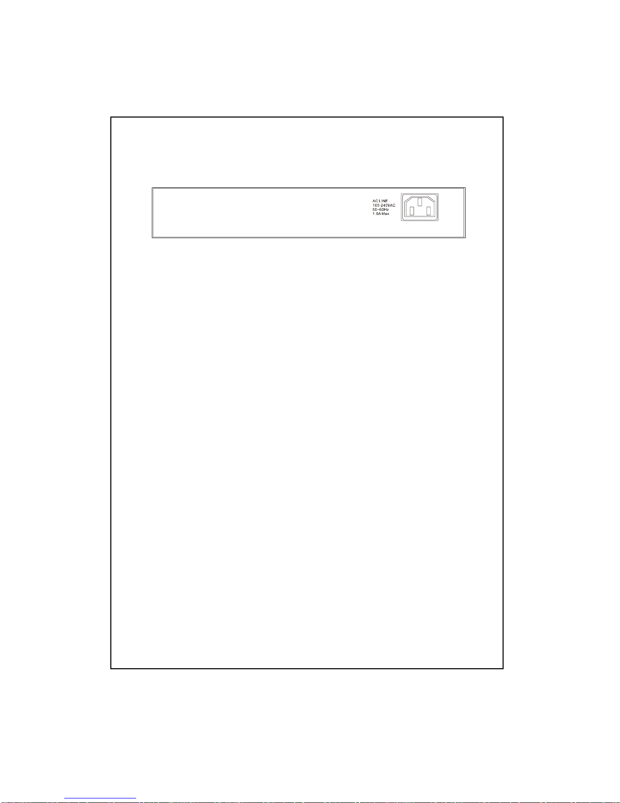
power outlet. Plug in all network connections and the power cord, then the system is
ready.
When deciding where to put the switch, you must ensure:
It is accessible and cables can be connected easily
Cabling is away from - Sources of electrical noise such as radio, transmitters,
broadband amplifiers, and fluorescent lighting fixtures.
Water or moisture can not enter the unit
Air flow around the unit and through the vents in the side of the case is not
restricted (company recommend that you provide a minimum of 25mm
clearance)
To prolong the operational life of your units:
Never stack units more than eight sets high if freestanding.
Do not place objects on top of any unit or stack
Do not obstruct any vents at the sides of the case
3.1.2 Rack-Mount Installation (rack-mount kit is optional)
The switch may standalone, or may be mounted in a standard 19-inch equipment rack.
Rack mounting produces an orderly installation when you have a number of related
network devices. The switch is supplied with two optional mounting brackets and
screws. These are used for rack mounting the unit.
Rack Mounting the Switch
The switch should be able to fit in the 19-inch rack.
1. Disconnect all cables from the switch before continuing.
2. Place the unit on a hard, flat surface with the front facing toward you.
3. Locate a mounting bracket over the mounting holes on one side of the unit.
4. Insert the screws and fully tighten with a suitable screwdriver.
5. Repeat the two previous steps for the other side of the unit.
6. Insert the unit into the 19-inch rack and secure with screws.
10
7. Reconnect all cables.

3.1.3 Installing Network Cables
After placing the switch on the desktop, we need to know how to connect the device
to network.
3.1.3.1 Station Connections with Twisted-Pair Cable
Connect each station to the switch by a category 5 twisted-pair cable
(straight or cross-over cable). Plug one RJ-45 connector into a front-panel
port of the switch, and plug the other RJ-45 connector into the station’s
network adapter.
3.1.3.2 Switch to Switch Connections with Twisted-Pair Cable
In making a switch to switch connection, you could use any port to connect
another switch with straight or cross-over cable.As all ports support auto
MDI-X function, the connection is independent of cable type. Thus, a straight
cable is also allowed to make a switch-to-switch connection.
In order to increase the bandwidth between switch and switch, you could use
the Gigabit ports to connect each other.
11

3.1.3.3 NetworkApplication
12

4. Switch Operation
4.1 MAC Address Table and Learning
The switch is implemented with a MAC address table where is composed of many entries.
Each entry is used to store the address information of network nodes on the network,
including MAC address, port ID, etc. The information is the most important base to do packet
filtering and forwarding.
When one packet comes in from any port, the switch will learn the source address, port ID,
and the other related information in address table. Therefore, the content of the MAC table
will update dynamically.
4.2 Filtering and Forwarding
When one packet comes in from any port of the switch, it will check the destination address
besides the source address learning. The switch will look up the address table for the
destination address. If not found, this packet will be forwarded to all the other ports except
the port where this packet comes in. If found, and the destination address is located at
different port from this packet comes in, the packet will be forwarded to the port where this
destination address is located according to the information of address table. But, if the
destination address is located at the same port as this packet comes in, this packet will be
filtered.
4.3 Store and Forward
Store-and-forward is one kind of packet-forwarding methodology.As a store-and-forward
switch, it will store the complete packet in the internal buffer and do the complete error
checking before transmitting to the network. Therefore, no error packets will disturb the
network. It is the best choice when a network needs efficiency and stability.
13

5. Console Program
Console Port
The switch provides a RS-232 console port for direct console management.
Pin Description
1 DCD (Data Carrier Detect)
2 RX (Receive)
3 TX (Transmit)
4 DTR (Data Terminal Ready)
5 GND (Ground)
6 DSR (Data Set Ready)
7 RTS (Request To Send)
8 CTS (Clear To Send)
9 N/A
When connecting a terminal directly to the switch, use a serial RS232 (straight through)
cable.
Console Management
Provide out-of-band management via console user interface (RS-232)
Please follow de-factor standard VT-100 terminal. Otherwise, the terminal will show
disorder display.
14
(RS-232 DB-9, DCE/female connector)
5 1
9 6

System Test – Power on Self Test
After power on, the system will run Power on Self Test Program. The screen will show as
below.
Remark:
If there are any error messages, please contact your local distributor for detail information.
15

Main menu
After system test program, the first setting screen is shown as below:
This powerful 8+2 Gigabit NWay Switch provides the following management function:
Function Control Key
<Shft_1> Port Config Check operating status of all ports and setup the
port configuration, like speed, duplex mode and
flow control.
[Shift] + [1]
<Shft_2> VLAN Config Supports up to 10 groups of port-based VLAN
group or 802.1Q VLAN function. [Shift] + [2]
<Shft_3> Trunk Config Review and setup the port trunk function. It
supports up to 4 port trunk groups of eight
10/100Mbps ports.
[Shift] + [3]
<Shft_4> Misc Config Including priority map, traffic monitoring, MAC table
auto-aging and broadcast storm control. [Shift] + [4]
<Ctrl_W> Apply Apply the setting. [Ctrl] + [W]
<Ctrl_D> Reset to Default Reset to initial state. [Ctrl] + [D]
<Tab> Next Item Move to next setting. [Tab]
<Space> Toggle Change the item. [Space]
<BackSpace> Previous Item Return to previous item. [Backspace]
Remark:
When you decide to apply the setting, please remember to press the control key [Ctrl] + [W].
Otherwise, if you press [Enter] key first, all the setting, which has not been applied, will be
refreshed. Please try again.
16

Port Status/Configuration
The port setting menu includes:
Port speed and duplex mode setting: 10/100/1000Mbits, half/full duplex mode and
auto-negotiation
Flow control: enable/disable.
You could change the default setting by the function key.
For example:
If you want to set port 1 to auto-negotiation and let flow control enable, please follow the
directions listed as below:
1. Move the cursor to port 1 “Spd/Dpx” setting column by pressing [Tab].
2. Press [Space] to select “Auto” auto-negotiation mode.
3. Then press [Tab] to “FlowCtrl” setting column.
4. Press [Space] to select flow control “Enable” function.
5. Press [Ctrl] and [W] at the same time to apply to setting value.
You can return to the previous item by press [Backspace]. Otherwise, you can just press
[Ctrl] and [D] at the same time to give up the current setting and reset to default.
17

VLAN Status/Configuration
This powerful 8+2 Gigabit NWay Switch provides two types of VLAN function:
Port-based VLAN
802.1Q VLAN tag
You can select VLAN types or just disable the VLAN function.
For example:
If you want to disable the VLAN function, please follow the directions listed below:
1. Press [Space] to select “Disable” VLAN function.
2. Press [Ctrl] and [W] at the same time to apply to setting value.
You can return to the previous item by press [Backspace]. Otherwise, you can just press
[Ctrl] and [D] at the same time to give up the current setting and reset to default
18

VLAN Status/Configuration – Port-based VLAN
This switch provides 10 port-based VLAN groups. Each group can contain 0-10 ports. The
group overlap is allowed.
You can select some ports into the same VLAN group by symbol “V”. If the packets without
the tagging frames come into one port, which only belongs to one VLAN group, the packets
just can be forwarded to another ports of this VLAN group.
For example:
If the VLAN groups is configured as below:
1 2 3 4 5 6 7 8 9
0
VLAN1 [ v v v - - - - - -
- ]
VLAN4 [ v v v
]
VLAN7 [ v v v v
v ]
When one packet without VLAN tag comes into port 1, the packet could be forwarded to
VLAN group:VLAN1,VLAN7. Thus, only port 2,3,7,8,9,0 will receive this packet, and other
ports of this switch will not. On the other hand, if another packet comes into port 6, it will not
be forwarded to any port of this switch because that port 6 does not belong to any VLAN
group.
19

VLAN Status/Configuration – 802.1Q VLAN
This switch provides 10 groups of 802.1Q VLAN function. Each group can contain 0-10 ports.
The group overlap is allowed.
You can select some ports into one VLAN group by symbol “V”. If the packets come into
one port with the same VLAN tag as this coming port’s VLAN ID, the packets just can be
forwarded to another ports of this VLAN group. If the packets come into one port without
VLAN tag, the PVID of this port will be automatically added into the packets as it’s VLAN tag.
In one word, all packets without the same VLAN ID could not be forwarded to other ports.
The “Tagged Port” indicates the aware or unaware VLAN device connected with the port.
For example:
If the VLAN groups is configured as below:
VID Member Port Tagged Port Port PVID
1~4094 -
1 2 3 4 5 6 7 8 9
0 - - - 1 2 3 4 5 6 7 8 9
0 -------- 1~4094
[ 222 ] [
v v - - - - - - v
- ] [
- v - - - - - -
- ] 1 [ 54 ]
[ 34 ] [
v - - v - v v - -
- ] [
- - - - - v - - -
- ] 2 [ 222 ]
[ 533 ] [
- - v - - v v - -
- ] [
- - - - - - v - -
- ] 3 [ 222 ]
20
Table of contents
Other Longshine Switch manuals

Longshine
Longshine LCS-GS8208-A User manual

Longshine
Longshine LCS-SW2402S User manual

Longshine
Longshine LCS-883R-SW8GS User manual

Longshine
Longshine LCS-GS-9316 Quick start guide

Longshine
Longshine GS8116-A User manual

Longshine
Longshine LCS-GS9116 User manual

Longshine
Longshine GS9120 User manual

Longshine
Longshine FSP8108-4 User manual

Longshine
Longshine LCS-883R-SW2402 User manual

Longshine
Longshine LCS-GS9420-A User manual