Longtime LCH-1260-2 User manual

LCHSERIES
USERMANUAL
ThankyouforselectingthisACtoDCBatteryCharger.Pleasereadthismanualcarefullybefore
installingandstartingupthisdevice.
Pleasereadthismanual!
Thismanualprovidessafety,installationandoperatinginstructionsthatwillhelpyouderive
thefullestperformanceandservicelifethatthisBatteryChargerhastooffer.
Pleasesavethismanual!
ItincludesimportanceinstructionsforthesafeuseofthisBatteryChargerandforobtaining
factoryserviceshouldtheproperoperationoftheBatteryChargercomeintoquestion.
Pleasesaveorrecyclethepackagingmaterials!
TheBatteryCharger’sshippingmaterialsweredesignedwithgreatcaretoprovideprotection
fromtransportationrelateddamage.Thesematerialsareinvaluableifyoueverhavetoreturn
theBatteryChargerforservice.Damagesustainedduringtransitisnotcoveredunderthe
warranty.
1.GENERALSAFETYANDINSTALLATIONINSTRUCTIONS
1‐1OperatingtheDeviceSafely
Failuretoobservethisinstructioncancausematerialdamage,devicemalfunction,ordanger
ofbodilyinjuries.Fundamentalsafetymeasuresshouldbeobservedwhenusingelectrical
equipmenttoavoidthedangerof:
zElectricshock
zFirehazard
zInjury
1‐2SafetyInstructionswheninstallingthedevice
zHandlethebatterieswithcare;theycontainstrongacids.
zAvoidcontactwiththebatteryfluidagent.Ifcomeincontactwithbatteryfluid,oneshould
rinsetheaffectedpartsofthebodyorclothingwithplentyofcoldwaterandseekmedical
attentionimmediately.
zBesurethatthedevicehasafirmfoundation.
zDonotusesharporhardobjectstocleanthedevice;doingsomaycausedevicedamage.
1‐3ElectricalCables
zIfcableshavetobefedthroughmetalwallsorotherwallswithsharpedges,useductsor
wirebushingstopreventdamage.
zLaythecablessothatotherpeoplewillnottripoverthem.
zDonotlaycableswhicharelooseorbentnexttoelectricallyconductivematerials.
zDonotpullthecables.
zFastenthecablesproperly.
zLaythecablessothattheycannotbeeasilydamaged
zAlwaysusesocketsthataregroundedandsecuredbyearthleakagecircuitbreaker.
zOnlyaspecialistshouldmaketheelectricalconnections.
zDonotlaythe115VAC/230VAClineandthe12VDCdirectcurrentinthesamecableduct.
zKeeptotheindicatedminimumcablecross‐section.
1‐4InstallationonBoats
Incorrectuseorinstallationofthechargeronboatmayleadtocorrosionoftheboat.Please
allowqualifiedpersonneltoperformtheinstallationofthecharger.
2.WARNING
zUsethechargeronlyasintended.
zDonotoperatethechargerifthehousingorthecablesaredamaged.
zThechargermaynotbeusedtochargeanyothertypeofbatteriesthantheonesindicated.
zDonotoperatethedeviceinadamporwetenvironment.
zDonotchargeafrozenbattery;thereisthedangerofexplosion.
zKeepthischargerinasafeplace,outofreachofchildren.
zOnlyqualifiedpersonnelwhoarefamiliarwiththerisksinvolvedandtherelevant
regulationsshouldcarryoutmaintenanceorrepairwork.
zThedevicemustbefixedandinstalledinsuchawaythatitwillnotfalloverorfalldown.
3.APPLICATIONSANDDESCRIPTIONS
Thechargersregeneratepowerorrechargemobilebatteriesusedonboardvehiclesorboats.
Thechargercancontinuouslychargesupplybatteriesorstarterbatteries,enablingthe
batteriestomaintainatahighcapacitylevel.
P2
P1

Thechargercanbeusedforchargingthreetypesofbatteries:
zGelbatteries
zLead‐acidstarterbatteries
zMaintenance‐freebatteries
Pleaseinquireyourbatterysupplieraboutthemaximumcapacitiesofyourlead‐acidbatteries.
Thechargerisequippedwithapolarityprotection;thispreventsthechargerfrombeing
damagedincaseofincorrectpolarity.
Atemperaturesensor(modelnumberTF‐500)thatisconnectedatthebatterybeingcharged
protectsthebatteryagainstdamagecausebyvaryingoutsidetemperaturebyadaptingthe
chargingvoltageofthetemperaturetothebattery.PleaseconnecttwoendsofTF‐500as
figure13–oneendto“T.S.”jackonrearpanelandanotherendtobattery.
Anoptionalremotecontrol(modelnumber900‐RC)canbeobtainedinordertoprovide
remoteaccesstothecharger.
4.SPECIFICATIONOFTHEUNITSVARIANTS
TheIU0Uautomaticchargercandeliverdifferentunitvariants.Itcanchargebatteriesupto
thespecifiedbatterycapacityasindicatedinthespecificationsection.Regardingthe
identificationofthespecificationofyourunit,locateyourmodelnumberinthefollowing
tables.
4‐1Rearview(seefigure6‐8)
No.Description
1Connectionforthetemperaturesensor
2Unitfuse
3Powerswitch
4Connectionfor115/230voltsvoltagesupply115/230V
5Ventilationoutlet
4‐2FrontviewofLCH‐1280‐2,LCH‐2440‐2,LCH‐1260‐2,LCH‐2430‐2,LCH‐1245‐2,LCH‐2425‐2
(seefigure1).Theunitscanchargeuptotwosupplybatteries.
No.Description
1Halfpowermode
2Connectionforremotecontrol(accessory900‐RC)
3Controllamp
No.Description
4Switchfieldfortheselectionofthechargingvoltageandtimelimitation(seefigure12)
5“+“(plus)terminalforthesupplybattery
6“+”(plus)terminalforthesupplybattery
7“‐“(minus)terminalforthesupplybattery
4‐3FrontviewofLCH‐1260‐3,LCH‐2430‐3,LCH‐1245‐3,LCH‐2425‐3(seefigure2).Theunits
canchargeuptothreesupplybatteries.
No.Description
1Halfpowermode
2Connectionforremotecontrol(accessory900‐RC)
3Controllamp
4Switchfieldforselectionofthechargingvoltageandtimerfunction(seefigure12)
5‐7“+“(plus)terminalforthesupplybattery
8“‐“(minus)terminalforthesupplybattery
4‐4FrontviewofLCH‐1225‐2,LCH‐2415‐2(seefigure3).Theunitscanchargeuptotwo
supplybatteries.
No.Description
1Halfpowermode
2Connectionforremotecontrol(accessory900‐RC)
3Controllamp
4Switchfieldfortheselectionofthechargingvoltageandtimerfunction(seefigure12)
5“+“(plus)terminalforsupplybattery
6“+“(plus)terminalforsupplybattery
7“‐“(minus)terminalforsupplybattery
4‐5FrontviewofLCH‐1225‐3,LCH‐2415‐3(seefigure4).Theunitscanchargeuptothree
supplybatteries.
No.Description
1Halfpowermode
2Connectionforremotecontrol(accessory900‐RC)
3Controllamp
4Switchfieldfortheselectionofthechargingvoltageandtimerfunction(seefigure12)
5“+“(plus)terminalforsupplybattery(1ACharge)
6“+“(plus)terminalforsupplybattery
7“+“(plus)terminalforsupplybattery
8“‐“(minus)terminalforsupplybattery
P4
P3

4‐6FrontviewofLCH‐1215‐2(seefigure5).Theunitscanbeusedtochargetwosupply
batteries.
No.Description
1Halfpowermode
2Connectionforremotecontrol(accessory900‐RC)
3Controllamp
4Switchfieldfortheselectionofthechargingvoltageandtimerfunction(seefigure12)
5“+“(plus)terminalforsupplybattery(1ACharge)
6“+“(plus)terminalforsupplybattery
7“‐“(minus)terminalforsupplybatter
5.ACCESSORIES
5‐1Thetemperaturesensor
Thetemperaturesensormeasuresthetemperatureofthebatteryortheenvironmentaround
thebatteryandtransfersthedatatotheIU0Uautomaticcharger.Withdeviating
temperatures,thechargingvoltageincreasesanddecreasesaccordingly.
zLaythecablesfromthebatteriestotheIU0Uautomaticcharger.
zConnectthetemperaturesensortothebackoftheIU0Uautomaticchargerviathesocket.
zAttachthesensorheaddirectlytothebattery.Usee.g.double‐sidedadhesivetapetoattach
thesensortothetopofthebatteryorinthevicinityofthebattery(seefigure13).
zSwitchtheIU0Uautomaticcharger“OFF“and“ON“againtoactivatethetemperature
sensor.
5‐2Remotecontrol
TheremotecontrolcanswitchthechargerONandOFFaswellasbeusedforfunctionalcheck.
*Note:Attachtheremotecontrolatawellaccessibleplacetoensureeasyaccessofthe
IU0Uautomaticcharger.
*Caution:Becarefulwhenattachingtheremotecontrol,forwiringharnesses,cablesand
othercomponentsthatareintheassemblyrangecouldbedamagedintheprocess.
zEnsureapproximately1.97”width,2.17”heightand0.91”depthforthetake‐upofthe
remotecontrol.
zConnecttheremotecontroltotheIU0Uautomaticcharger.Theconnectioncableis
equippedwithtwoequivalentmodularplugs.
zPlacetheremotecontrolintotheopeningcreated.Securetheremotecontrolwithscrews
ontheupperandbottommarginofthefaceplate–usetheavailabledrills.
*Note:Connecttheplugofthe115/230voltsvoltagesupplyattheunittoagrounded
socketthatissecuredbyanearthleakagecircuitbreaker.
*Note:ThepowerswitchattheunitmustbeswitchedON,sothattheunitcanbeswitched
ONandOFFwiththeremotecontrol.
6.SETTINGS
6.1Chargingvoltageandtime
Aswitchfieldcanselectthechargingvoltageandtheperiodforthemainchargingphase.
*Warning:Makesurethatswitch1and2orswitch3and4areneverswitchedon
simultaneouslywhileoperatingthecharger.Pleasefollowthetablebelowtoensurecorrect
operationofthecharger
SettingsforthechargingvoltageforLCH‐1280‐2,LCH‐1260‐2,LCH‐1260‐3,LCH‐1245‐2,
LCH‐1245‐3,LCH‐1225‐2,LCH‐1225‐3andLCH‐1215‐2:
12VChargingVoltageSwitch1Switch2Applicationrange
13.8VOFFOFFOldstarterbatteries
mainschargeroperation
14.4VONOFFWetandgelbatteries
14.8VOFFONFleecebatteries
SettingsforchargingvoltageforLCH‐2440‐2,LCH‐2430‐2,LCH‐2430‐3,LCH‐2425‐2,
LCH‐2425‐3,LCH‐2415‐2andLCH‐2415‐3:
24VChargingVoltageSwitch1Switch2Applicationrange
27.6VOFFOFFOldstarterbatteries
mainschargeroperation
28.8VONOFFWetandgelbatteries
29.6VOFFONFleecebatteries
P5P6

Settingsforthelimitationoftheperiodofthemainchargingphase:
Timelimitationofthemaincharging
phase
Switch4Switch3Applicationrange
4hrsONOFFWetbatteries
8hrsOFFONGelbatteries
NotimerfunctionOFFOFF
ModelNo.Supplybattery
LCH‐1280‐2AWG#4~AWG#2
LCH‐1260‐2/LCH‐1260‐3AWG#6~AWG#4
LCH‐2440‐2/LCH‐1245‐2/LCH‐1245‐2AWG#7~AWG#6
LCH‐1225‐2/LCH‐1225‐3/LCH‐2425‐2
LCH‐2425‐3/LCH‐2430‐2/LCH‐2430‐3AWG#10~AWG#8
6‐2Halfpowermode
Ifyoupushthebutton“HalfPowerMode”,theoutputpowerwillreducetohalfthechargers
ampratingandagreen“HalfON”LEDwilllight.TheHalfPowerLEDislocatedonthe
bottomleftcornerofthefrontpanel.
7.MAKINGCONNECTIONS
zPlacethechargerinadry,cool,clean,andventilatedspace.
zSetthepowerswitchto“0”(off)andpulloutthemainplugbeforeconnectionor
disconnectingthedirectcurrentconnection.
zConnectthe“‐“(minus)batterypolewithaconnectingcablewiththe”‐“(minus)terminalat
theIU0Uautomaticcharger(seefigure9).
zConnectthe“+”(plus)batterypolewiththeconnectingcablewiththe“+”(plus)terminalat
theIU0Uautomaticcharger(seefigure9).
zLaythecablesfromthebatteriestotheIU0Uautomaticcharger.
zFoldthecableendswiththemulticorecableends.
zForconnectionofstarterbatteries,pleaseconnecttheterminalasourdrawing
(seefigure11).
zSupplythecablewithaforkconnectionforanideaconnectionwiththeterminal(seefigure
10).
Ensurecorrectpolarityofthebatteryandthebatterycharger,otherwisetheinternalflat‐pin
terminalwilltriggerwiththewrongpolarity.
*Warning:Batterieswithcellconnectionmaynotbecharged.Explosivegasescouldresult
frombatteryoverheating.
*Note:OnlyusecableswiththedesignatedwirecrosssectionstoconnecttheIU0U
automaticchargertothebattery.
LCH‐1215‐2/LCH‐2415‐2/LCH‐2415‐3AWG#12~AWG#10
8.USINGTHECHARGER
8‐1Usingtheremotecontrol
ThepowerswitchattheunitmustbeswitchedONsothatthechargercanbeswitchedON
andOFFwiththeremotecontrol.
8‐2Chargingcharacteristic
ThechargingcharacteristicisgenerallydesignatedasamodifiedIU0Ucharacteristic.
P7P8

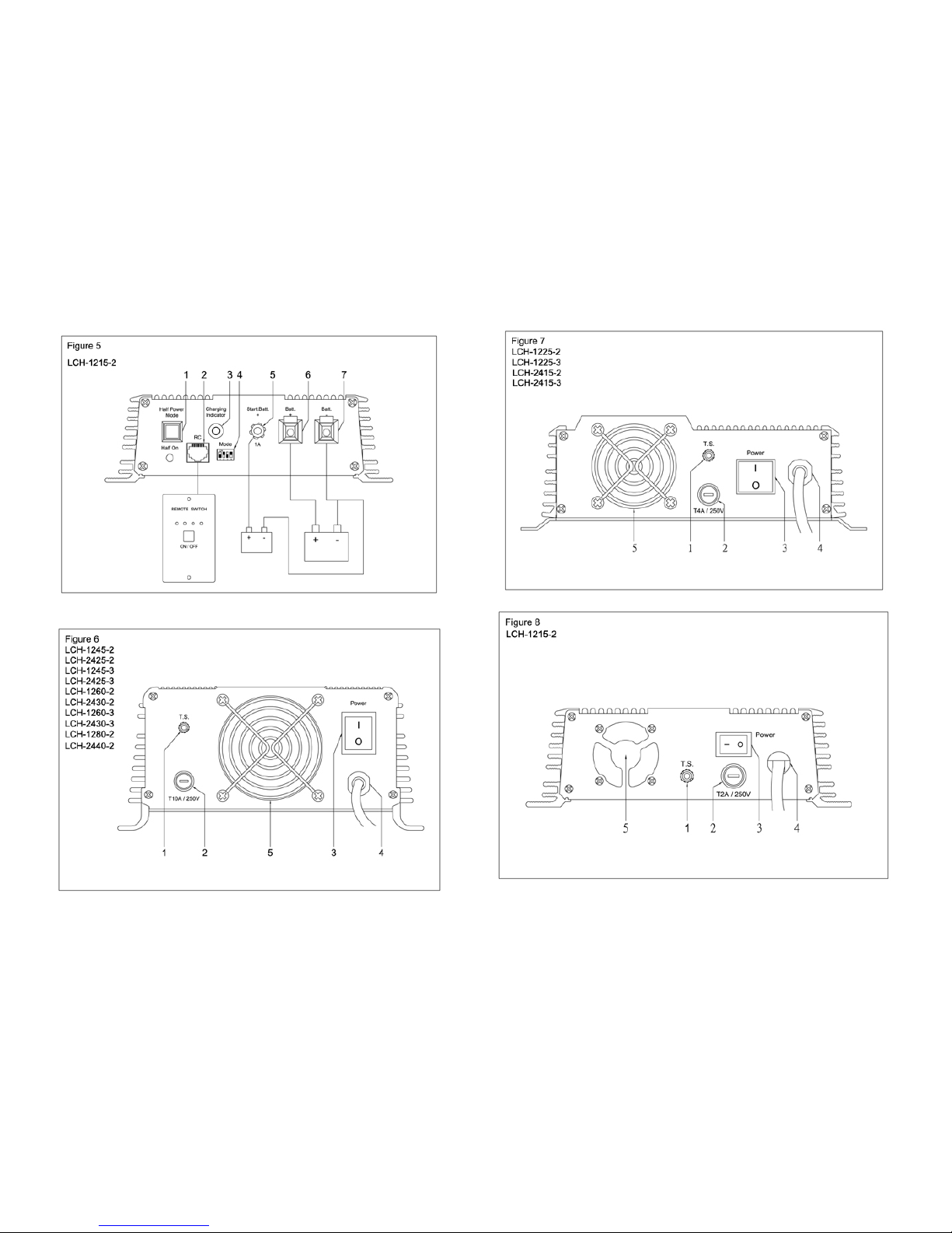
*Note:ThebatterychargersLCH‐1215‐2,LCH‐1225‐3andLCH‐2415‐3haveachargingoutput
forthestarterbattery.Theoutputvoltageisbetween13.2V(26.4V)and13.8V(27.6V)and
canrechargethestarterbatterywithacurrentof1Aorkeepitatahighcapacitylevel.
zIphase:Inthefirststageofthechargingprocess,thedepletedbatteryischargedwitha
constantcurrentuntilthebatteryvoltagereaches13.8Vor27.6V.Whenthebatteryreaches
thisvoltagelevel,thechargingcurrentgraduallydrops.Whenthecurrentdropsdownto
80%,thechargerswitchesovertothehigherchargingvoltageof14.4V/14.8Vor28.8V/
29.6V.
*Note:Thechargingvoltageandtheperiodforthemainchargingphase(U0phase)canbe
selectedusingtheswitchfield.
zU0phase:Thismainchargingphaseislimitedamaximumof4/8hoursandthecurrent
risesagaintoitsmaximumvalue.Thecurrentremainsconstantaslongasthebattery
voltageisbelow14.4V/14.8Vor28.8V/29.6V.Afterreachingthemaximumvoltage,it
remainsconstant.However,thecurrentdropsagain.Withinthismainchargingphase,which
islimitedto4/8 hours,thebatteryisfullycharged.
zUphase:Ifthecurrentdecreasesto10%orundertheratedcurrentorifthetimelimitof4/
8hoursisexceeded,thenthechargerswitchesovertoeconomycharging(13.8Vor27.6V).
*Note:Batteriesmaybechargedseparatelyfromeachotherifthechargershavedouble
chargingorthree‐foldchargingconnections.Theoutputsareseparatedinternallybydiodes,
thustheweakerbatteryisalwaysfirstsettothecharginglevelofthestrongerbattery.
*Attention:Themaximumbatterycapacityshouldnotexceedthespecifiedcapacity,
otherwisethefunctionsoftheindividualchargingphasescouldbeinfluenced.
8‐3UnitswithTemp eratu re Sensor
Atemperaturesensorcanbeconnectedinordertoprovidetheoptimumcharging
functioning.Thechargingvoltages,ascanbeseenfromthediagram,vary,dependingonthe
batterytemperature
8‐4Functionalcheck
zChargingphases:TheLEDinthefrontoftheunitcanbeusedtocheckthestatusofthe
chargingprocess.
*Note:Theoptionalremotecontrolcanalsobeusedtocheckthestatusofthecharging
process.TheLEDsontheremotecontrolindicatethedifferentchargingphaseswithits
respectivecolors.
LEDChargingphaseChargingstatusofthebattery
redIphasebetween10%and50%
yellowU0phasebetween10%and50%
greenUphaseover90%
9.TROUBLESHOOTING
9‐1Afterconnectingandchargingthebattery,thebatteryvoltagewouldnotincrease.
zIfpossible,measurewithasuitablemultimeterduringthechargingtoverifyifthevoltage
atthebatteryterminalsincreases.
zDeterminewhethertheterminalsareconnectedproperlytothebatterypoles.Cleanthe
batterypolesifnecessarytoensurebetterconnection.
9‐2Afterachargingtimeofapprox.20hours,thebatteryisstillnotfullycharged
zDisconnectthepowertotheIU0Uautomatic.
zRemovethebatteryfromthechargingterminalsandwaitforafewminutes.
zThen,measurethevoltageatthebatteryterminalswiththemultimeter.
12Vbattery:Ifthemultimeterdisplaysavoltageof10Vorless,thisindicatesthatthebattery
isdefectiveandcannotbecharged.
24Vbattery:Ifthemultimeterindicatesavoltageof20Vorbelow,allowthebatterybe
checkedbyaspecialist,ifnecessary.Otherwise,disposeofthebattery.
9‐3Thebatterydischargesafterashortperiodoftimewithoutusage.
zMeasurethevoltageatthebatteryterminalswithasuitablemultimeter.Ifthemultimeter
indicatesavoltagebelow12Vofa12Vbatteryoravoltagebelow24Vofa24Vbattery,then
thebatteryistooweaktoretainthecharge.
P9P10


This manual suits for next models
13
Other Longtime Batteries Charger manuals