WSTECH BATD0050-ES-1-400-1 User manual

Original Operating Instructions
Battery Charger
Table of Contents
O_BATD0050-ES-1-400-1_V2.6_GB
Original Operating Instructions
Battery Charger
BATD0050-ES-1-400-1
WSTECH is a Wind&Sun Technologies and Siemens Joint Venture.
Before starting any work please read „Operating Instructions“ and
„Interface Description Modbus TCP and EtherCAT“.

Original Operating Instructions
BATD0050-ES-1-400-1
Table of Contents
O_BATD0050-ES-1-400-1_V2.6_GB
Page 2of 72
Table of Contents
1User Information ........................................................................ 7
1.1 Identification of the Product...................................................................8
1.2 Scope.................................................................................................... 9
1.3 Target Audience....................................................................................9
1.4 General Information............................................................................... 9
1.4.1 Related Documents......................................................................10
1.4.2 Symbols........................................................................................10
1.4.3 Terms and Abbreviations..............................................................11
1.5 Intended Use.......................................................................................12
1.6 Safety Instructions...............................................................................13
1.7 Fire Protection Measures ....................................................................15
1.8 Safety Sign on the Product..................................................................15
1.9 Safety Signs on the Packaging............................................................16
2Description................................................................................17
2.1 Functional Description.........................................................................17
2.2 Principle of the Product....................................................................... 17
2.3 Options................................................................................................19
2.4 Views...................................................................................................19
2.4.1 Exterior View................................................................................. 19
2.4.2 Interior View.................................................................................. 20
3Installation ................................................................................ 21
3.1 Delivery ............................................................................................... 21
3.2 Transport.............................................................................................22
3.2.1 Transport with Crane....................................................................23
3.3 Storage................................................................................................24
3.4 Installation Site.................................................................................... 25
3.4.1 Distances...................................................................................... 27
3.4.2 Cooling ......................................................................................... 28
3.5 Connections ........................................................................................30
3.5.1 Required Connections.................................................................. 31

Original Operating Instructions
BATD0050-ES-1-400-1
Table of Contents
O_BATD0050-ES-1-400-1_V2.6_GB
Page 3of 72
3.5.2 Optional Connections ...................................................................40
3.6 After Installation................................................................................... 44
4Commissioning ........................................................................45
4.1 Preparing Commissioning ...................................................................46
4.2 Performing Measurements before Operation ...................................... 48
4.2.1 Voltage Measurement DC Voltage and AC Voltage .....................49
4.2.2 Voltage Measurement Harmonic Filter .........................................49
5Operation .................................................................................. 50
5.1 User Interfaces.................................................................................... 50
5.2 Operating Modes.................................................................................50
5.3 Enable Switch...................................................................................... 51
5.4 Starting the Product.............................................................................52
5.5 Performing Measurements..................................................................52
5.5.1 AC Voltage.................................................................................... 52
5.5.2 AC Current....................................................................................53
5.5.3 Ambient Temperature................................................................... 53
5.6 Stopping the Product...........................................................................53
6Troubleshooting.......................................................................54
6.1 BAT Error Codes................................................................................. 56
6.1.1 BAT Error Codes 11-21 ................................................................ 57
6.1.2 BAT Error Codes 22-29 ................................................................ 57
6.1.3 BAT Error Codes 66-68, 71-73, 76-78, 116-118, 121-123, 126-128,
175................................................................................................57
6.1.4 BAT Error Codes 81, 82, 131, 132................................................57
6.1.5 BAT Error Codes 151, 155............................................................57
6.1.6 BAT Error Code 156..................................................................... 58
6.1.7 BAT Error Code 157..................................................................... 58
6.1.8 BAT Error Code 158..................................................................... 58
6.1.9 BAT Error Code 159..................................................................... 58
6.1.10 BAT Error Codes 161-163............................................................58
6.1.11 BAT Error Codes 164 ................................................................... 58
6.1.12 BAT Error Codes 169 ................................................................... 58

Original Operating Instructions
BATD0050-ES-1-400-1
Table of Contents
O_BATD0050-ES-1-400-1_V2.6_GB
Page 4of 72
6.1.13 BAT Error Code 171..................................................................... 58
6.1.14 BAT Error Codes 172, 174............................................................59
6.2 BAT Warning Codes............................................................................60
6.2.1 BAT Warning Codes 12, 14, 16, 17-21.........................................60
6.2.2 BAT Warning Codes 22-29........................................................... 60
6.2.3 BAT Warning Code 170................................................................ 60
7Maintenance.............................................................................. 61
7.1 Maintenance every 12 Month..............................................................62
7.2 Maintenance in De-energized Condition .............................................62
7.2.1 Visual Inspection of Housing.........................................................62
7.2.2 Visual Inspection of Interior Area.................................................. 62
7.2.3 Torque Check of Electrical Connections.......................................63
7.2.4 Condition Check of Cables and Lines...........................................63
7.2.5 Condition Check of Fuses............................................................. 63
7.2.6 Functional Test of DC Circuit Breaker .......................................... 63
7.2.7 Functional Test of AC Circuit Breaker...........................................64
7.2.8 Functional Test of Enable Switch..................................................64
8Decommissioning .................................................................... 65
8.1 Disconnecting Voltage Measurement and Supply Voltage..................65
9Disposal .................................................................................... 66
10 Customer Service..................................................................67
11 Annex...................................................................................... 68
11.1 Spare Parts List...................................................................................68
11.2 Technical Data ....................................................................................69
11.2.1 Electrical Data............................................................................... 69
11.2.2 General Data ................................................................................70
11.3 EU Declaration of Conformity..............................................................71

Original Operating Instructions
BATD0050-ES-1-400-1
Table of Contents
O_BATD0050-ES-1-400-1_V2.6_GB
Page 5of 72
List of Figures
Figure 1: Example of a type plate..................................................................................8
Figure 2: Example of an option plate.............................................................................8
Figure 3: Schematic structure.....................................................................................18
Figure 4: Exterior view front........................................................................................19
Figure 5: Interior view front .........................................................................................20
Figure 6: Transport with crane ....................................................................................23
Figure 7: Cable entry area (bottom view)....................................................................26
Figure 8: Mounting points (bottom view) .....................................................................27
Figure 9: Bottom view.................................................................................................28
Figure 10: Top view ....................................................................................................29
Figure 11: Sliding ground plate ...................................................................................30
Figure 12: AC connection............................................................................................32
Figure 13: DC connection ...........................................................................................33
Figure 14: Connection supply voltage (-X1)................................................................34
Figure 15: Connection data communication................................................................36
Figure 16: Terminal strip (-X17) ..................................................................................37
Figure 17: Wiring diagram extract terminal strip (-X17)..............................................37
Figure 18: Connection option Interface for SBB16-10.................................................38
Figure 19: Connection supply voltage and PLC ..........................................................39
Figure 20: Feedback Enable switch ............................................................................41
Figure 21: Cable routing to terminal strip (-X17)..........................................................44
Figure 22: Measurement points...................................................................................47
Figure 23: Danger area...............................................................................................51

Original Operating Instructions
BATD0050-ES-1-400-1
Table of Contents
O_BATD0050-ES-1-400-1_V2.6_GB
Page 6of 72
List of Tables
Table 1: Naming convention .......................................................................................11
Table 2: Scope of delivery...........................................................................................21
Table 3: Feedback of insulation monitoring device......................................................42
Table 4: Extract of BAT Error Codes...........................................................................56
Table 5: Extract of BAT Error Codes (continued) ........................................................57
Table 6: Extract of BAT Warning Codes......................................................................60
Table 7: Maintenance in De-energized condition (every 12 months) ..........................62
Table 8: Torque of electrical connections....................................................................63
Table 9: Spare parts list..............................................................................................68
Table 10: Electrical data .............................................................................................69
Table 11: General data ...............................................................................................70

Original Operating Instructions
BATD0050-ES-1-400-1
User Information
O_BATD0050-ES-1-400-1_V2.6_GB
Page 7of 72
1 User Information
We congratulate you on purchasing a BATD0050-ES-1-400-1. By purchasing this
battery charger, you have chosen a high-quality WSTECH product. If you have
Legal Information
All rights reserved. Reproduction, also in extract form, only admissible with approval
from the manufacturer.
Trademarks
All trademarks are recognized, even if they are not identified as such.
EtherCAT®is a registered trademark and patented technology, licensed by Beckhoff
Automation GmbH, Germany.
Modbus®fieldbus is a registered trademark of Schneider Electric and is licensed by the
Modbus Organization, Inc.
QR Code®is a registered trademark of DENSO WAVE INCORPORATED.
Manufacturer
WSTECH GmbH
Eckernförder Landstraße 78
D-24941 Flensburg
Tel.: +49-(0) 461-430122-0
Fax: +49-(0) 461-430122-11
E-Mail: inf[email protected]om
Web: www.wstech.com
Issue: 12/2019

Original Operating Instructions
BATD0050-ES-1-400-1
User Information
O_BATD0050-ES-1-400-1_V2.6_GB
Page 8of 72
1.1 Identification of the Product
The type plates and option plates of the BATD0050-ES-1-400-1 (hereinafter referred to
as BAT or product) are located on the outside and inside of the front cabinet door.
Figure 1: Example of a type plate
Pos.
Description
1
Manufacturer
2
Hardware- and wiring diagram version
3
Technical data DC input
4
Degree of protection
5
Technical data AC output
6
Product denomination
7
Serial number
Figure 2: Example of an option plate

Original Operating Instructions
BATD0050-ES-1-400-1
User Information
O_BATD0050-ES-1-400-1_V2.6_GB
Page 9of 72
1.2 Scope
These original operating instructions (hereinafter referred to as operating instructions)
are valid for the following products:
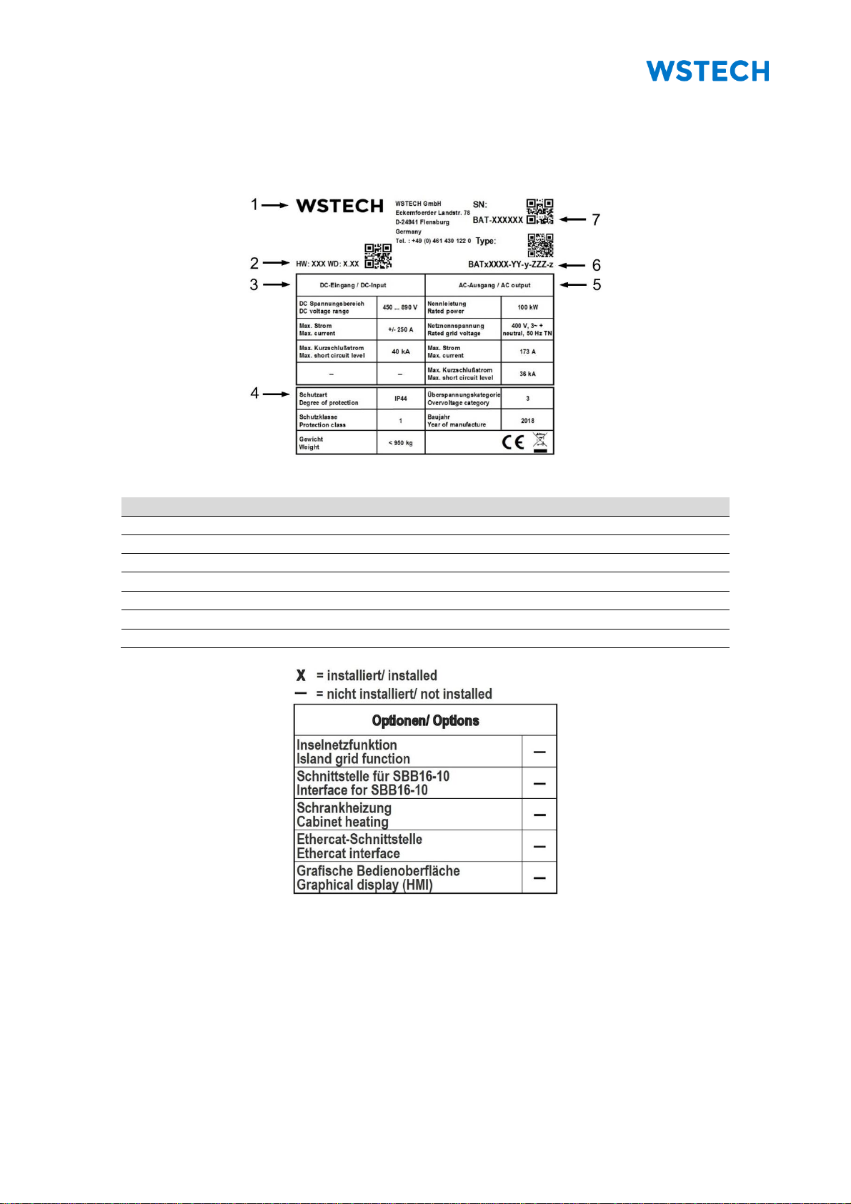
•BATD0050-ES-1-400-1 (hardware version: 130, wiring diagram version: 2.XX)
The illustrations used in these operating instructions are reduced to the essentials and
may differ from the delivered product. The manufacturer may from time to time change
these operating instructions and content therein.
1.3 Target Audience
All work on the product must be performed by qualified electricians.
Qualified electricians in the sense of these operating instructions are persons familiar
with installation, mounting, commissioning, operating, troubleshooting, maintenance,
decommissioning and disposal of this product. They are familiar with the hazards
involved as well as work- and safety regulations of the product and have the
appropriate qualifications. They know how batteries work and are operated.
Unauthorized persons are not allowed to operate the product. These persons must
keep a safe distance from the product.
The transport of the product must be performed by trained and authorized persons with
the appropriate qualifications.
1.4 General Information
These operating instructions provide detailed information regarding specifications,
installation procedures, operation, commissioning, troubleshooting, maintenance,
decommissioning, technical data, safety procedures and function settings of the
product. The operating instructions and the related documents exist only in electronic
form.
The manufacturer constantly adapts its products according to the latest state of the art
of science and technology and therefore it assumes, that its products are free from
defects in the sense of product liability. However, it cannot be excluded that for
operation in critical application areas additional safety measures can be necessary.
The manufacturer requests the user of its products, in their own interest, to inform his
contractors and the manufacturer about the application of its products to initiate
possible additional safety measures.
The utilization and the service life of the product, as well as the avoidance of premature
repairs depend on the proper commissioning, operation, maintenance and care. For
professional maintenance follow the instructions contained in these operating
instructions.
The manufacturer recommends the notice of these operating instructions to be
acknowledged in writing by the personnel and noted in the personnel file.
The manufacturer recommends translation of these operating instructions into the
native languages of foreign workers.

Original Operating Instructions
BATD0050-ES-1-400-1
User Information
O_BATD0050-ES-1-400-1_V2.6_GB
Page 10 of 72
1.4.1 Related Documents
This and the related documents are provided on an USB Stick in the product.
•Interface Description Modbus TCP and EtherCAT (hereinafter referred to as
Interface Description)
•Wiring diagram
1.4.2 Symbols
Symbol
Description
DANGER!
Indicates a direct danger situation which will lead to death or severe
injuries.
WARNING!
Indicates a possible danger situation which can lead to death or severe
injuries.
CAUTION!
Indicates a possible danger situation which can lead to lesser or lighter
injuries.
NOTICE
Indicates a possible danger situation which can lead to damage to
property or to the environment.
Use head protection.
Use hand protection.
Disconnect and safeguard against reconnection.
Pay attention to supplementary documents to these operating
instructions.
WEEE identification.
ESD sensitive components

Original Operating Instructions
BATD0050-ES-1-400-1
User Information
O_BATD0050-ES-1-400-1_V2.6_GB
Page 11 of 72
1.4.3 Terms and Abbreviations
Table 1: Naming convention
Complete designation
Designation in the document
Alternating current
AC
Battery inverter
BAT
Constant current–constant voltage
CC-CV
Direct current
DC
Electromagnetic compatibility
EMC
Electrostatic discharge
ESD
Energy storage
ES
Ethernet for Controller and Automation
Technology
EtherCAT
Hardware version
HW
Human-machine-interface
HMI
Insulated gate bipolar transistor
IGBT
International protection
IP
String Booster Box
SBB
Transmission control protocol
TCP
Uninterrupted power supply
UPS
Waste of Electrical and Electronic Equipment
WEEE
Wiring diagram version
WD

Original Operating Instructions
BATD0050-ES-1-400-1
User Information
O_BATD0050-ES-1-400-1_V2.6_GB
Page 12 of 72
1.5 Intended Use
This product is intended for use exclusively with batteries.
The product is constructed for indoor use. It fulfils the IP20 degree of protection.
The product is not suitable for operation in areas with the risk of explosion and must be
kept away from flammable or combustible materials.
For all work appropriate tools must be used.
All work may only be carried out in compliance with the ESD protection measures.
Only operate the product with the maximum permissible connected loads stated in
Section Electrical Data.
The operating conditions given in the technical data must be fulfilled at all times.
The manufacturer must not be liable for damages resulting from other persons
conducting work on the product.
The type plate, safety signs and labels must remain permanently attached to the
product.
Only the spare parts that are listed in this document may be used. The use of other
spare parts must be construed as an alteration.
Without approval of the grid operator do not switch off or adjust settings which have
influence on the grid management service.
Any changes and/or modifications to the equipment, its structure and its software are
prohibited and will result in loss of warranty.
Intended use includes reading these operating instructions and complying with all
instructions contained herein, in particularly the safety instructions. The operating
instructions must be kept near or in the product for the lifetime of the product.
Should these operating instructions get lost or are destroyed, the customer must
immediately contact the manufacturer to order, at customer's sole expense, a new
operating instructions.

Original Operating Instructions
BATD0050-ES-1-400-1
User Information
O_BATD0050-ES-1-400-1_V2.6_GB
Page 13 of 72
1.6 Safety Instructions
DANGER!
Danger to life due to disregarding the instructions for action!
Disregarding the safety instructions or performing unauthorized
actions may lead to serious injury or death.
•Read and observe all safety instructions, warnings and
symbols on the product and within these operating
instructions.
•Observe the existing industrial safety measures for work,
operation and safety regulations to the installation site.
•No activities may be performed without appropriate
authorization or qualification.
•For questions contact customer service.
DANGER!
Danger to life due to high voltage!
After pressing the Enable switch or switching the AC circuit breaker in
position OFF, dangerous voltage is present. Touching live parts can
result in death or serious injury due to electric shock.
•Before working on the product, check that it is disconnected
externally and safeguarded against reconnection.
•After stopping and before opening the product, observe a
minimum wait time of at least 30 minutes prior to opening.
•Do not touch live parts.
•Check that no residual voltage is present within the DC link by
means of suitable testing equipment.
•Check that no residual voltage is present within the harmonic
filter by means of suitable testing equipment.
•During operation the door of the product must remain closed.
•No protection or security devices may be temporarily or
permanently removed, altered or adjusted.
•Provide earth connection before connecting to the AC/DC
power.
•Observe all warnings from the battery manufacturer.
•Observe that the AC/DC cables are still under voltage if they
are not disconnected from the product externally.

Original Operating Instructions
BATD0050-ES-1-400-1
User Information
O_BATD0050-ES-1-400-1_V2.6_GB
Page 14 of 72
NOTICE
Damage to components due to electrostatic discharge!
Electrostatic discharge can damage the components.
•Wear suitable personal protective equipment for all work on
the product.
•Perform all work on the product in accordance to
IEC 61340-5-1.
•Avoid direct contact with components on PCB or its
conducting path.
•Before working on the product earth yourself by touching a
grounded object.
NOTICE: The manufacturer does not accept responsibility for errors or damages if
safety regulations are not met during handling, operation and maintenance.

Original Operating Instructions
BATD0050-ES-1-400-1
User Information
O_BATD0050-ES-1-400-1_V2.6_GB
Page 15 of 72
1.7 Fire Protection Measures
DANGER!
Danger to life due to fire or explosion!
Unsuitable installation sites can cause fire or explosion. This may
cause damage to the product and result in serious injury or death.
•No installation in potentially explosive atmospheres.
•No installation on inflammable materials.
•No installation in atmospheres, such as in the presence of
inflammable materials.
WARNING!
Danger to life due to fire or explosion!
There is risk of fire and explosion if inflammable solvents are used.
•Use only non-flammable solvents for cleaning.
NOTICE: During maintenance and repair work always ensure the area around the
product is clean and persons working on the product adhere to high cleanliness
standards.
1.8 Safety Sign on the Product
DANGER!
Danger to life due to high voltage!
Risk of electrical shock from not completely discharged
capacitors.
•Wait minimum 30 minutes after stopping before working
on the product.
The safety sign is located on the front door (Figure 4).

Original Operating Instructions
BATD0050-ES-1-400-1
User Information
O_BATD0050-ES-1-400-1_V2.6_GB
Page 16 of 72
1.9 Safety Signs on the Packaging

Original Operating Instructions
BATD0050-ES-1-400-1
Description
O_BATD0050-ES-1-400-1_V2.6_GB
Page 17 of 72
2 Description
2.1 Functional Description
The product can feed the energy stored in batteries power controlled into the grid. For
this purpose it converts the DC voltage of the batteries into grid-compliant AC voltage.
If required, reactive power can be provided. To charge the batteries from the grid the
inverter operates as a controlled rectifier.
2.2 Principle of the Product
Figure 3 shows the schematic structure of the product with its main components. The
connection of the batteries is provided at the DC circuit breaker. The product transfers
energy from the grid into the DC link and vice versa.
The control card controls the power semiconductors and measures the AC side and
DC side currents and voltages. It measures the temperatures of the power
semiconductors. The control card detects the positions of the circuit breakers and the
Enable switch. The communication with the control card is provided via the user
interface.

Original Operating Instructions
BATD0050-ES-1-400-1
Description
O_BATD0050-ES-1-400-1_V2.6_GB
Page 18 of 72
Figure 3: Schematic structure

Original Operating Instructions
BATD0050-ES-1-400-1
Description
O_BATD0050-ES-1-400-1_V2.6_GB
Page 19 of 72
2.3 Options
Following options are available for each product:
•Island grid function
•Interface for SBB16-10
•Cabinet heating
•EtherCAT-Interface
•Graphical display (HMI)
2.4 Views
2.4.1 Exterior View
Figure 4: Exterior view front
Pos.
Description
1
Graphical display (HMI) (Option)
2
Enable switch (-S1)
3
Safety sign
4
Rotary handle for AC circuit breaker (-Q2)

Original Operating Instructions
BATD0050-ES-1-400-1
Description
O_BATD0050-ES-1-400-1_V2.6_GB
Page 20 of 72
2.4.2 Interior View
Figure 5: Interior view front
Pos.
Description
1
DC link measurement points
2
DC link
3
Power stack
4
Control card (-A1) (-A2)
5
Fuse (-F8), Insulation
monitoring device
6
Terminal strip (-X3), Current
and voltage measurement
7
Motor protecting switch, (-F31)
Voltage measurement
8
Fuses (-F10, -F11), Precharge
circuit
9
Fuses (-F13, -F14), (Option)
Interface for SBB16-10
10
Circuit breaker (-Q101) (Option)
Interface for SBB16-10)
11
DC circuit breaker (-Q1)
12
Terminal strip (-X13), (Option)
Interface for SBB16-10
13
Terminal strip (-X17), Island
grid function and temperature
measurement
14
AC EMC filter (-C2),
AC connection
15
AC circuit breaker (-Q2)
16
Terminal strip (-X1), Supply
voltage connection;
Terminal strip (-X2), Feedback
17
Surge arrester (-F30),
AC connection
18
Surge arrester (-F32)
19
Fuses (-F1), (F2)
Notch- and Harmonic filter
20
Option EtherCAT-Interface
(-A3)
21
Shock sensor
Table of contents
Other WSTECH Batteries Charger manuals