Longwei Electric LW-1000L User manual

1
Section one: General description
I、Introduction
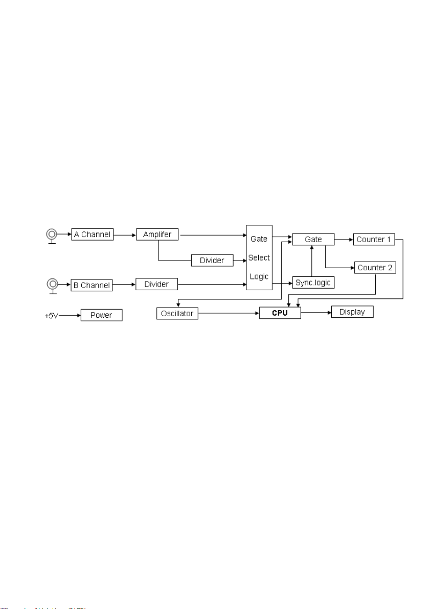
This instrument is one of multifunctional and hi-precision frequency counters
that measures frequency from 10Hz to 1000MHz
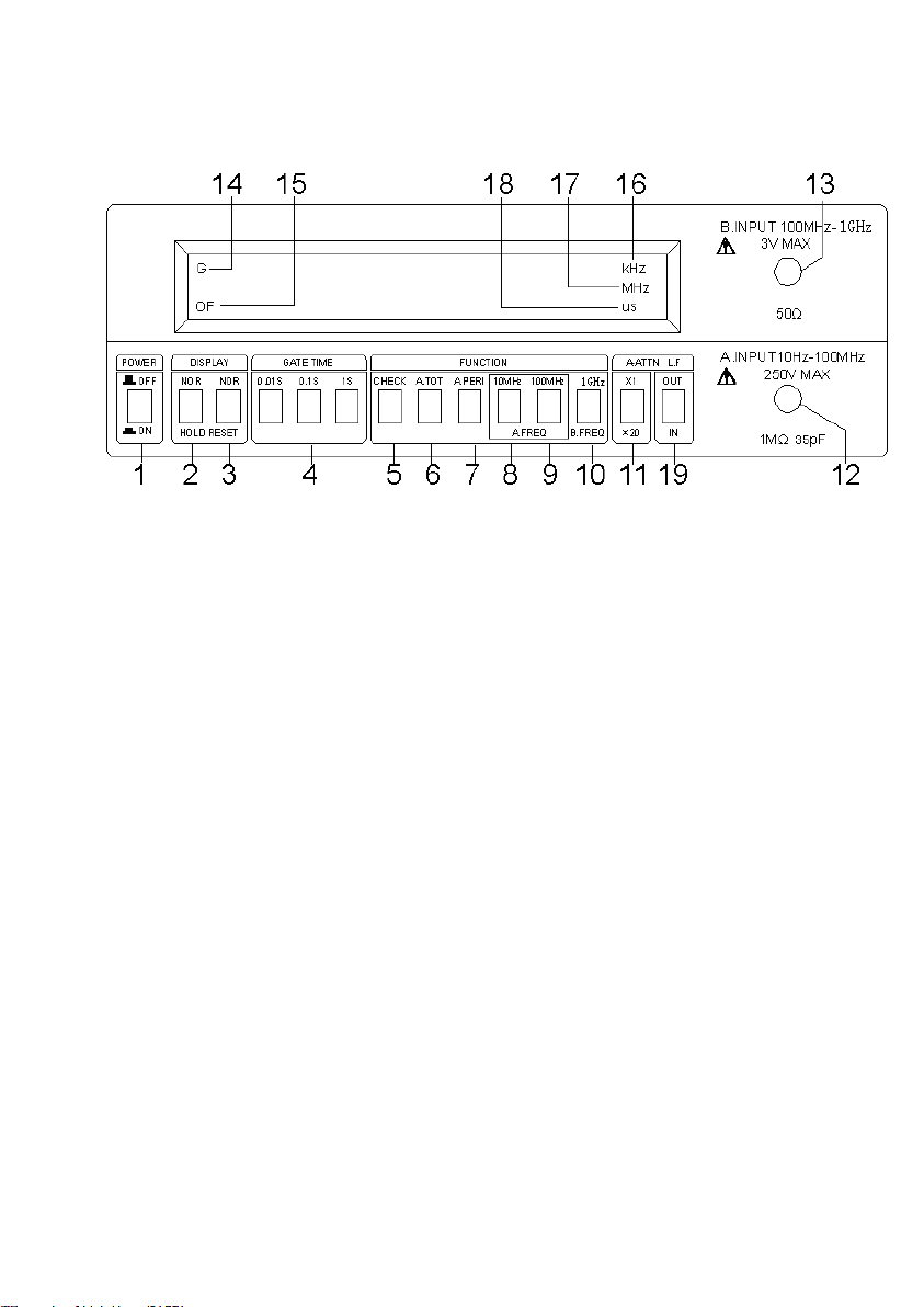
It has function for test of frequency, period, totalize and self-checking with
8digits, 7 segment bright LED display.
It has low power consumption circuit design, small size, light weight,
high-stabilized crystal oscillator which can ensure precise measurement and
full signal input checking. This hi-precision frequency counter is the first
choices for product-line, school laboratory and radio maintenance
II、Specification
The pertinent specifications are listed as follows:
1. Measuring mode
1) Frequency measurements.
Channel A
Range: 10Hz~10MHz direct count
10MHz to 100MHz count in proportion
Direct count: 1Hz、10Hz、100Hz switch selectable.
Count in proportion:10Hz、100Hz、1000Hz switch selectable.
Gate time: 0.01s, 0.1s, 1s switch selectable.
Accuracy: ±1 count value ±base time error ×measured frequency
Channel B
Range: 100MHz~1GHz
Resolution: 100Hz、1kHz、10kHz
Gate time: 0.01s 、0.1s、1s
Accuracy: ±1 count value ±base time error × measured frequency
2) Period measurement
Input: Channel A

2
Range: 10Hz~10MHz
Resolution:10-7s、10-8s、10-9s switch selectable
Accuracy: ±1count value ±base time error × measured period
3) Accumulated measurements
Input: Channel A
Range: 10Hz~10MHz
Resolution: ±1 count pulse
4. Self-checking
Display:8 LED display with 0~9 character simultaneous display
2. Input characteristics
1) Channel A
Input sensitivity
10MHz range:10Hz~8MHz 20mVrms
8MHz~10MHz 30mVrms
100MHz range:10MHz~80MHz 20mVrms
80MHz~100MHz 30mVrms
Attenuation: ×1, ×20 fixed
Filter (CH1 only) Low pass: AC 100 kHz-3dB
Impedance: Approximate 1MΩ (less then 35pF)
Maximum safety voltage: 250V (DC+ACrms)
2) Channel B
Input sensitivity: 20mVrms
Impedance: Approximate 50Ω
Maximum safety voltage: 3V
3. Time base
Time-base frequency 10MHz
Short- term stability: ±3×10⁻⁹ / 1s (average)
Long -term stability: 2×10⁻⁵ /month
Temperature Coefficient: ±1×10⁻⁵ ,0~40℃

3
Line voltage: the change of voltage of ±10% in each, the time-base frequency
change ±1×10⁻⁷
4. General
Display: 8 digits, 0.39 inch green LED display with decimal point, gate, KHz,
MHz and μs indication.
Power requirement: AC 220V ± 10% 50Hz
Warm-up time: 20 minutes when cold started at 25℃
Temperature: rated range of use: -5~50℃
Storage and transport: -40~60℃
Humidity: operating: 10~90%RH
Storage: 5~95%RH
Dimension: 240mm×205mm× 85mm
Weight: about 2kg
5. Supplied accessories
Power cord 1
User manual 1
Testing line 1
Section three: Operation instruction
This section provides complete operating information for hi-precision
frequency counter, including a description of all front panel controls,
connectors and indicators, operating instructions as well as operator’s
maintenance.
1. Preparation for use
1) Power requirements
AC220V ±10%, 50Hz signal phase, max powerdissipation: 10W
2) Warm up 20 minutes before use to make the frequency of crystal oscillator
stable.

4
2.Features of panel features
1) Power switch: press the button to turn on.
2) Hold: press this button, the instrument will stop test and keep the data
before stopping.
3) Reset: When pressed, immediately reset the counter to begin a new
measurement, usually used in the totalize mode to begin a new measurement.
4) Gate time: select different resolution and counting cycle when it used for
test of frequency and Cycle.
5) Check: check whether the counter and display function work normally.
Press this button, 8 LED display with 0~9 character simultaneous display
repeatedly.
6) A. TOT: Accumulation measurement. (Channel A input)
7) A. PERI: period test. (Channel A input)
8) A. FREQ: 10MHz: With this switch in, placed in 10MHz frequency
mode.(channelA input)
9) A. FREQ: 100MHz: With this switch in, placed in 100MHz range frequency
mode.(channel A input)
10) B. FREQ :( channel B input)
Switch: B FREQ. 1GHz
Range of frequency: 100MHz~1GHz

5
11) ATT: Input signal attenuator switch.
When pressed, the input sensitivity is reduced 20 times. (Only A input)
12) A INPUT: Channel A input connector.(When the amplitude of input signal
is more than 300mV, please press the “AT T ” to reduce the input signal to
improve to accuracy of test value).
13) B INPUT: Channel B input connector.
14) Gate indicator: indicator ON or OFF state of the GATE, When GATE is
ON, indicator is lighted.
15) OVERFLOW indicator: when the display over 8 digits, it is lighted.
16) KHz annunciator: the unit of frequency.
17) MHz annunciator: the unit of frequency.
18) Μs annunciator: the unit of period.
19) Lowpass filter: AC 100kHz ; 3dB
Attention: when all the function keys turn off , it will display model:
“F-1000L”
3. Rear panel features
Figure 3
20) 13MHz output: Output connector of internal reference oscillator, this
connector provides a 13MHz signal, It may be used as a reference signal for
other frequency counters.
21) AC INLET: Provides connection to AC power.
AC220V±10%, 50Hz

6
22) Fuse: AC power protection(0.3A/220V)。
Section two: Action principle
This instrument uses the principle of equal precision to measure frequency and
period. That is to say, in predefined time Tx (Gate time), counter 1 counts Nx
for integral pulses of measured signal while counter 2 counts No for standard
pulses, and then frequency Fx and period Px of the measured signal can be
determined by calculating formular easily.
Frequency Fx=Nx / Tx
Period Px=Tx / Nx
Section four: Calibration
1. Introduction
Calibration is limited to calibrate the base time oscillator frequency and the
trigger level.
Base time oscillator should be calibrated whenever the oscillator is maintained
or accuracy of the counter fails to meet the requirement. And the calibration of
base time should be made under the condition that ambient temperature is
between 22~25℃(72℉~77℉).before calibration, the instrument have to
warm up at least 30 minutes.

7
Warning
Maintenance described here in is performed with power supplied to the
instrument, And protective covers removed, such maintenance should be
performed only by service-trained personnel who are aware of the hazard
involved (For example, fire and electrical shock), Where maintenance can be
performed without power applied, the power should be removed.
2. Test instruments required.
Quartz oscillator Range: 13MHz~1GHz
Temperature coefficient: ±1×10⁻⁸
Sine wave generator Range: 10Hz~1MHz ; 1kHz~1GHz
3. Calibration of time-base frequency
1) Base time of channel A
a、input the signal that output by 10MHz Quartz oscillator to counter
A.INPUT.
b、Set the front panel controls as follow.
POWER ON
NOR / HOLD NOR
GATE TIME 1s
FUNCTION A.FREQ.10MHz
ATT ×1
c、when observing the counter display, the reading should be 10000,000……
±1digit. If there are some errors, please adjust the frequency controlled
capacitor C5 of time-base oscillator (see figure 4-1)
2) Base time of channel B
a) Input 1GHzstandard signal to counter B. INPUT.
b) Set the front panel controls as follow:
POWER ON
NOR / HOLD NOR
GATE TIME 1s

8
FUNCTION B.FREQ. ATT
c) When observing the counter display, the reading should be 1000.000±1. If
there are some errors, please adjust the frequency controlled capacitor C5 of
time-base oscillator (see figure 4-1)
4. Trigger level calibration
a) Set sine wave generator to 10Hz,10MHz two frequency points to calibrate,
amplitude to 20mVrms.
b) Connect generator to A. INPUT terminal of the front panel.
c) Set the front panel controls as follow
POWER ON
NOR / HOLD NOR
GATE TIME 1s
FUNCTION A.FREQ.10MHz
ATT ×1
d) Observing the count value, adjust the trigger level control (RP1 on the PCB)
to obtain a stable
Reading.
(Figure 4-1)
Table of contents
Popular Cash Counter manuals by other brands

Triton
Triton RL1600 Quick reference guide

Parametric
Parametric TCR-EU868 quick start guide

AccuBANKER
AccuBANKER AB4000 user guide

Precision Digital Corporation
Precision Digital Corporation Vantageview PD6720 manual

Lightning Protection International
Lightning Protection International LSR2 Technical data sheet

Flonidan
Flonidan UNIFLO G4S Series user manual

MZ electronic
MZ electronic WHC040 Instructions for use

Lighthouse
Lighthouse ApexZ Series Operator's manual

Innovative Instruments & Controls
Innovative Instruments & Controls Cx-428 User's operating manual

DAE Controls
DAE Controls CO-10 installation guide

Omron
Omron CJ1W-CTL41-E Operation manuals

Magnescale
Magnescale LG20 quick start guide