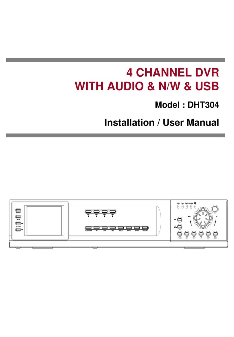
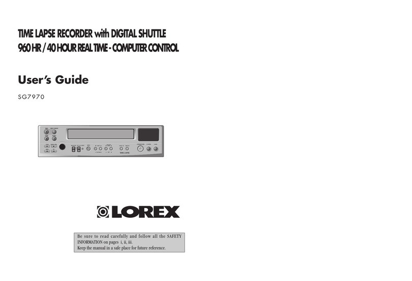
Lorex TR 1285 User manual

CLEAR/
BUZZER OFF
ALARM
STANDBY
PLAY/
REC CHK
REC / PB SPEED
TRACKING
POWER
TIMER MENU REC
LOW TAPE
CLOCK
COUNT/
REMAIN
STOP/
EJECT PAUSE/STILL
F.F
CUE
REW
REV
TIME LAPSE VIDEO CASSETTE RECORDERTIME LAPSE VIDEO CASSETTE RECORDER
SEL
MOVE
DOWN UP
/
PF
DEW
TAB
END
H
EP
SP
LINK
CLOCK COUNT REMAIN ALARM
VIDEO RECORDER
Installation and Operation Manual
Please read this manual thoroughly before use, and keep it handy for future reference.
30 Hour Real Time / Time Lapse VCR
168 Hour Time Lapse VCR
960 Hour Time Lapse VCR

FCC COMPLIANCE STATEMENT
FCC INFORMATION : THIS EQUIPMENT HAS BEEN TESTED AND FOUND TO COMPLY WITH THE LIMITS FOR A CLASS A
DIGITAL DEVICE, PURSUANT TO PART 15 OF THE FCC RULES. THESE LIMITS ARE DESIGNED TO PROVIDE
REASONABLE PROTECTION AGAINST HARMFUL INTERFERENCE WHEN THE EQUIPMENT IS OPERATED IN A
COMMERCIAL ENVIRONMENT. THIS EQUIPMENT GENERATES, USES, AND CAN RADIATE RADIO FREQUENCY ENERGY
AND IF NOT INSTALLED AND USED IN ACCORDANCE WITH THE INSTRUCTION MANUAL, MAY CAUSE HARMFUL
INTERFERENCE TO RADIO COMMUNICATIONS. OPERATION OF THIS EQUIPMENT IN A RESIDENTIAL AREA IS LIKELY
TO CAUSE HARMFUL INTERFERENCE IN WHICH CASE THE USER WILL BE REQUIRED TO CORRECT THE
INTERFERENCE AT HIS OWN EXPENSE.
CAUTION: CHANGES OR MODIFICATIONS NOT EXPRESSLY APPROVED BY THE PARTY RESPONSIBLE FOR
COMPLIANCE COULD VOID THE USER’S AUTHORITY TO OPERATE THE EQUIPMENT.
THIS CLASS A DIGITAL APPARATUS MEETS ALL REQUIREMENTS OF THE CANADIAN INTERFERENCE-CAUSING
EQUIPMENT REGULATIONS.
CET APPAREIL NUMÉRIQUE DE LA CLASSE A RESPECTE TOUTES LES EXIGENCES DU RÈGLEMENT SUR LE
MATÉRIEL BROUILLER DU CANADA.
i

WARNINGS AND CAUTIONS
TO REDUCE THE RISK OF FIRE OR ELECTRIC SHOCK, DO NOT EXPOSE THIS PRODUCT TO RAIN OR MOISTURE.
DO NOT INSERT ANY METALLIC OBJECTS THROUGH THE VENTILATION GRILLS OR OTHER OPENINGS ON THE EQUIPMENT.
CAUTION
EXPLANATION OF GRAPHICAL SYMBOLS
The lightning flash with arrowhead symbol, within an equilateral triangle, is intended to alert the user to the presence of
uninsulated "dangerous voltage" within the product's enclosure that may be of sufficient magnitude to constitute a risk of
electric shock to persons.
The exclamation point within an equilateral triangle is intended to alert the user to the presence of important operating
and maintenance (servicing) instruction in the literature accompanying the product.
CAUTION: TO REDUCE THE RISK OF ELECTRIC SHOCK, DO NOT REMOVE COVER (OR BACK).
NO USER-SERVICEABLE PARTS INSIDE. REFER SERVICING TO QUALIFIED SERVICE PERSONNEL.
CAUTION
RISK OF ELECTRIC SHOCK DO NOT OPEN
ii
Attention: Installation should be performed by qualified service personnel only in accordance with National Electrical
Codes or applicable local codes.
Power disconnect: Units with or without ON-OFF switches have power supplied to the unit whenever the power cord is
inserted into the power source; however, the unit is operational only when the ON-OFF switch is in the ON position.
The power cord is the main power disconnect for all units.
Polarized Attachment Plug Marking - for CNL use only.
CAUTION - TO PREVENT ELECTRIC SHOCK, MATCH WIDE BLADE OF PLUG TO WIDE SLOT,
FULLY INSERT.

IMPORTANT SAFEGUARDS
1. READ AND RETAIN INSTRUCTIONS
2. CLEANING
3. ATTACHMENTS
4. MOISTURE
5. ACCESSORIES
6. VENTILATION
7. POWER SOURCES
8. GROUNDING OR POLARIZATION
9. CORD AND CABLE PROTECTION
10. LIGHTNING
11. OVERLOADING
12. SERVICING
— Read the instruction manual before operating the equipment. Retain the manual for
future reference.
— Turn the unit off and unplug from the power outlet before cleaning. Use a damp cloth for cleaning. Do not use harsh
cleansers or aerosol cleaners.
— Do not use attachments unless recommended by manufactured as they may affect the functionality of the unit
and result in the risk of fire, electric shock or injury.
— Do not use equipment near water or other liquids.
— Equipment should be installed in a safe, stable location. Any wall or shelf mounting accessory equipment
should be installed using the manufacture’s instructions. Care should be used when moving heavy equipment.
Quick stops, excessive force, and uneven surfaces may cause the equipment to fall causing serious injury to persons and objects.
— Openings in the equipment, if any, are provided for ventilation to ensure reliable operation of the unit and to
protect if from overheating. These openings must not be blocked or covered.
— The equipment should be operated only from the type of power source indicated on the marking label.
If you are not sure of the type of power supplied at the installation location, contact your dealer. For equipment designed to operate
from battery power, refer to the operating instructions.
— Equipment that is powered through a polarized plug (a plug with one blade wider than the
other) will fit into the power outlet only one way. This is a safety feature. If you are unable to insert the plug fully into the outlet, try
reversing the plug. Do not defeat the safety purpose of the polarized plug.
Alternate Warning : If the equipment is powered through a three-way grounding-type plug, a plug having a third (grounding) pin,
the plug will only fit into a grounding-type power outlet. This is a safety feature.
Do not defeat the safety purpose of the grounding-type plug. If your outlet does not have the grounding plug receptacle, contact
your local electrician.
— Route power cords and cables in a manner to protect them from damage by being walked
on or pinched by items places upon or against them.
— For protection of the equipment during a lightning storm or when it is left unattended and unused for long periods
of time, unplug the unit from the wall outlet.
Disconnect any antennas or cable systems that may be connected to the equipment. This will prevent damage to the equipment
due to lightning or power-line surges.
— Do not overload wall outlets and extension cords as this can result in a risk of fire or electric shock.
— Do not attempt to service the video monitor or equipment yourself as opening or removing covers may expose you
to dangerous voltage or other hazards.
Refer all servicing to qualified service personnel.
iii
13. DAMAGE REQUIRING SERVICE
14. REPLACEMENT PARTS
15. SAFETY CHECK
16. FIELD INSTALLATION
— Unplug the equipment from the wall outlet and refer servicing to qualified service personnel
under the following conditions:
A. When the power supply cord or the plug has been damaged.
B. If liquid has spilled or objects have fallen into the unit.
C. If the equipment has been exposed to water or other liquids.
D. If the equipment does not operate normally by following the operating instructions, adjust only those controls that are covered
by the operating instructions. Improper adjustment of other controls may result in damage to the unit.
E. If the equipment has been dropped or the casing damaged.
F. When the equipment exhibits a distinct change in performance.
— When replacement parts are required, be sure the service technician uses replacement parts
specified by the manufacturer or that have the same characteristics as the original part. Unauthorized substitutions may result in
fire, electric shock, or other hazards.
— Upon completion of any service or repairs to the equipment, ask the service technician to perform safety
checks to verify that the equipment is in proper operating condition.
— The installation of equipment should be made by a qualified service person and should conform to all
local codes.

iv
TABLE OF CONTENTS
Congratulations on your choice of this time-lapse recorder. You have selected a high-quality, precision engineered instrument designed
to give you years of service.
To get the best performance from your new time-lapse recorder, it is important that you carefully read and follow the operating
instructions in this manual in the sequence in which they are presented.
Should you experience a problem, please follow the "Before Calling For Service" on pages 27.
Features 1
Overview 2
Front View 2
Display Window 3
Error Mode 3
Operating Conditions Displays 3
Back View 4
Terminal Description 5
Connecting with Other Equipment 6
Connecting a Camera and Monitor 6
Connecting a Switcher 6
Connecting another unit in Series 7
Loading and Unloading the Video Tape 8
Loading 8
Unloading 8
Preventing Accidental Erasure 8
Setting the Clock (Initial Clock Setting) 9
Date 9
Time 9
Daylight Savings 9
Date Format 9
Site ID 9
Menu Settings 10
Menu Overview 10
VCR Setup 11
Rec Mode Setup 11
Timer Rec Setup 12
Searches Setup 12
Alarm Setup 12
Power Fail Recall 12
Recording 13
Manual Record 13
Alarm Record 15
Link Record 18
One-Shot Record 18
Timer Record 19
Additional Features 20
Tape Counter 20
Counter Reset 20
Memory Back-Up in Case of Power Failure 20
Recording After a Power Failure 20
Power Failure Display 20
Remain 20
Playback 21
Audio Playback 21
How to Use the Shuttle Ring 22
During Still Mode 22
During Playback Mode 22
How to Use the Jog Ring 22
Special Effects Playback / Adjustment During Playback 23
Still Picture 23
Tracking Adjustment 23
Vertical Adjustment 23
Remote Control 24
RS-232C Parameter Setup 25
Before Calling for Service 27
Specifications 28

FEATURES
*
*
*
*
*
*
*
*
*
*
*
*
*
*
*
*
*
*
*
Real-time 30 hours recording capacity (40 hours with T-160)
Dual mode on screen display
Linear Audio (up to 30 hours)
RS232C PC control (Option)
Wireless remote control (Accessory)
Camera switching pulse
2 weeks battery back-up
Universal power
Flexible timer recording
Multiple OSD Languages (English, French, Spanish)
Jog shuttle
Alarm record
Link record
One-shot record
Alarm scan
Alarm index search
Power fail recall
Low energy consumption (approx. 12 Watts)
Microphone input
NOTE : The VCR accepts a wide range of power inputs requiring no manual switching : 100-240 VAC, 50/60Hz
1

OVERVIEW
1. POWER/TIMER button
2. MENU button
3. REC (RECORD) button
4. MOVE button
5. SELECT button
6. DOWN button
7. UP button
8. LOW TAPE
9. ALARM STANDBY
Press to select the timer program - on or off. By setting
power off, a timer program is set to work.
Press to display and change the settings of the VCR while
viewing on the video monitor.
Press to begin recording.
Press to move the cursor down to the next available option
on the menu screen, or to adjust the tracking during the
playback or slow mode.
Press to change the value of a setting on the menu screen or
to operate tracking during playback or slow playback.
Press to select from a descending order, the record/playback
speed (960H, 168H...).
Press to select from an ascending order, the record/playback
speed (6H, 18H, 30H...).
This light starts blinking to warn that the tape is nearing the
end (approx. 3 minutes remaining).
A buzzer also sounds.
To turn this optional feature off, change the setting in the
VCR Setup Menu.
This LED illuminates when the alarm record feature detects
an alarm. It can be disabled by changing the setting under
REC TIME on the ALARM SETUP menu.
(Press for on; press again for off)
The display window becomes brighter when the VCR
is switched on.
10. Cassette loading slot
11. CLOCK, COUNT, REMAIN
12. CLEAR, BUZZER OFF
13. Shuttle Ring
14. Jog Ring
15. STOP/EJECT button
16. PAUSE/STILL button
17. PLAY/REC CHK
Cassette tape is inserted in this slot.
Pressing this button toggles between the CLOCK,
COUNT and REMAIN displays. CLOCK shows the
current time, COUNT shows the incremental counter
for recording or playing, and REMAIN indicates the
remaining time on the tape.
Press to delete the information stored on the screen
display, such as Alarm recall, Power fail and Timer program.
It can also be used to stop the buzzer sound or to
alarm record if it is held for at least 3 seconds.
Refer to page 22.
Refer to page 22.
Press once to discontinue all tape related functions.
Press a second time to eject the cassette.
When pressed during recording, tape movement stops
temporarily. Press again to continue the recording.
When pressed during playback, tape movement stops.
Press again to advance by still frame.
Press to play back a previously recorded tape.
Pressing this button while recording provides confirmation of
the recording operation. The tape plays back the last 4
seconds of video then returns to the recording mode.
FRONT VIEW
CLEAR/
BUZZER OFF
ALARM
STANDBY
PLAY/
REC CHK
REC / PB SPEED
TRACKING
POWER
TIMER MENU REC
LOW TAPE
CLOCK
COUNT/
REMAIN
STOP/
EJECT PAUSE/STILL
F.F
CUE
REW
REV
TIME LAPSE VIDEO CASSETTE RECORDERTIME LAPSE VIDEO CASSETTE RECORDER
SEL
MOVE
DOWN UP
/
10 13 14
321
15 16 1746 75 9 12118
2

1. REPEAT REC
2. RECORD LOCK
3. Cassette status indicator
4. Timer record
5. REC indicator
6. CLOCK indicator
7. COUNT indicator
8. REMAIN indicator
Indicates repeat recording is ON.
Indicates record settings are locked and cannot be
accidentally erased.
Illuminates when tape is inserted.
Appears when the timer record option is programmed.
Illuminates during recording and when TIMER REC is set to
ON.
Indicates the current time.
Indicates the relative position on the tape.
Indicates the tape's remaining time.
E-1: Displayed when no tape is loaded.
E-2: Displayed when tape does not insert or eject.
E-3: Displayed when the tape will not eject.
E-4: Displayed when tape will not move.
E-5: Displayed when drum is out of order.
*
*
Press the power button or the RESET button to release the
error when an error message displays.
Check condition of the tape.
Appears when an alarm recording occurs and remains on
ALARM RECALL list.
Indicates a power failure occurred.
Indicates the tape operation.
Appears when the tape has no security tab.
Appears when the tape reaches the end during recording.
Appears when LINK REC is turned on.
Indicates Clock, Count, Remain and error mode.
Indicates tape speed during playback or recording.
9. ALARM indicator
10. PF indicator
11. PLAY, CUE, REVIEW, STILL, SLOW
12. TAB indicator
13. END indicator
14. Link indicator
15. DIGIT, Error indicator
16. Speed indicator
Playback display Display other than Playback
Playback Recording
Still Pause
Slow playback Timer recording
Forward search (CUE) Alarm recording
Reverse search (REVIEW) Rewinding
Reverse playback Fast forwarding
English
DISPLAY WINDOW
ERROR MODE
OPERATING CONDITIONS DISPLAYS
12 3 4 5 6 7 8 9 10
11
12 13 14 15 16
PF
DEW
TAB
END
H
EP
SP
LINK
CLOCK COUNT REMAIN ALARM
REC
REC
REC
REC
OVERVIEW (CONTINUED)
3

1. GND (GROUND) terminal
2. ALARM IN terminal
3. ALARM OUT terminal
4. LINK IN terminal
5. LINK OUT terminal
6. TRIGGER OUT terminal
7. TAPE END terminal
This is the common ground for the other seven terminals.
Input for alarm recording. Alarm sensor is connected to this
terminal.
Output to an external alarm. Activates when the VCR is in the
Alarm Mode.
Input for recording in series with multiple VCRs.
Output for recording in series with multiple VCRs.
Output to control an external camera switcher.
Output to indicate when tape has finished recording or if there
has been a problem during recording.
(Separate circuitry required to activate external buzzer)
8. 1-SHOT REC terminal
9. AUDIO IN connector
10. AUDIO OUT connector
11. VIDEO IN connector
12. VIDEO OUT connector
13. MIC IN
14. RESET
15. RS232C option
Input for external signal to trigger single field recording after
setting REC TIME 000H on menu.
Audio input connector (RCA)
Audio output connector (RCA)
Input connector for video signal (BNC)
Output connector for video signal (BNC)
Microphone Input
Press to restart the VCR after any errors occur. Resetting the
VCR will not erase the settings programmed in the menu
mode.
14
6
589
10
23 711
12131415
GND
IN OUT IN OUT
TRIG
OUT
TAPE
END
1SHOT
REC
ALARM LINK
IN
OUT
MIC IN
AUDIO
IN
OUT
VIDEO
RS232C
RESET
4
OVERVIEW (CONTINUED)
BACK VIEW

TERMINAL DESCRIPTION
GND
IN OUT IN OUT
TRIG
OUT
TAPE
END
1SHOT
REC
ALARM LINK
VIH
VIH
VIH
VIH
VIH
VIH
VIH
VIL
VIL
VIL
VIL
VIL
VIL
VIL
T
T
T
T
T
T
T
TERMINAL NAME
GND GND
ALARM IN INPUT
VIH:4~5V
VIL : 0 ~ 0.6V
T : More than 0.5 second
VIH:4~5V
VIL : 0 ~ 0.6V
T : Alarm Recording
VIH:4~5V
VIL : 0 ~ 0.6V
T : More than 0.5 second
VIH:4~5V
VIL : 0 ~ 0.6V
T : More than 1 second
VIH:4~5V
VIL : 0 ~ 0.6V
T : About 0.02 second
VIH:4~5V
VIL : 0 ~ 0.6V
T : More than 0.25 second
VIH:4~5V
VIL : 0 ~ 0.6V
T : More than 0.5 second
ALARM OUT OUTPUT
LINK IN INPUT
LINK OUT OUTPUT
TRIGGER OUT OUTPUT
TAPE END OUTPUT
1 SHOT REC INPUT
SIGNAL LEVEL TYPE
5
OVERVIEW (CONTINUED)

CONNECTING WITH OTHER EQUIPMENT
1. Disconnect the power before connecting to other equipment.
2. Connect the camera, monitor, switcher, multiplexer and additional VCR as described below.
3. Plug in the power cord into the outlet.
4. Turn on the power.
With the following connections,
you can monitor video
and audio.
CAMERA SWITCHING PULSE
The triggering pulse out of the
VCR helps switchers or multiplexers
synchronize camera switches
with the VCR recording time.
The longer the recording interval,
the greater the benefit of this
synchronization feature.
NOTE :
1. This switching pulse feature
only works with multiplexers
or switchers with "passive"
dwell-times whose intervals
are automatically adjusted by
triggering pulses.
2. When you connect several
cameras to a switcher,
synchronize the cameras or
the video quality may be poor.
CONNECTING A CAMERA AND MONITOR
CONNECTING A SWITCHER
VIDEO IN
VIDEO OUT
AUDIO OUT
GND
IN OUT IN OUT
TRIG
OUT
TAPE
END
1SHOT
REC
ALARM LINK
IN
OUT
MIC IN
AUDIO
IN
OUT
VIDEO
RS232C
RESET
VIDEO CAMERA
CAMERA SWITCHER
or MULTIPLEXER
VIDEO
OUT
MONITOR
OUT
TRIGGER
IN
1
2
3
4
TRIGGER
OUT
GND
VIDEO CAMERAS
6
VCR Interconnection cable
AUDIO OUT
VIDEO OUT
AUDIO IN
VIDEO IN
GND
IN OUT IN OUT
TRIG
OUT
TAPE
END
1SHOT
REC
ALARM LINK
IN
OUT
MIC IN
AUDIO
IN
OUT
VIDEO
RS232C
RESET
VIDEO CAMERA
to AC POWER
MONITOR
ACIN
OFF
1 CA1
CA2
CA3
CA4
OUT
VCROUT
ALARM
OUT
VCRIN
VCR
NO
NC
C
IN
2
3
4

CONNECTING WITH OTHER EQUIPMENT (CONTINUED)
NOTE:
"NO VIDEO" will display on a blue background if there is no video signal on the VIDEO IN connector.
When the buzzer option is set to on, an alarm sounds. It can be canceled by pressing the CLEAR/BUZZER button once.
Alarm record can also be turned off by pressing and holding the CLEAR/BUZZER OFF button for three seconds.
*
*
*
CONNECTING ANOTHER UNIT IN SERIES
GND
IN OUT IN OUT
TRIG
OUT
TAPE
END
1SHOT
REC
ALARM LINK
IN
OUT
MIC IN
AUDIO
IN
OUT
VIDEO
RS232C
RESET
GND
IN OUT IN OUT
TRIG
OUT
TAPE
END
1SHOT
REC
ALARM LINK
IN
OUT
MIC IN
AUDIO
IN
OUT
VIDEO
RS232C
RESET
GND
IN OUT IN OUT
TRIG
OUT
TAPE
END
1SHOT
REC
ALARM LINK
IN
OUT
MIC IN
AUDIO
IN
OUT
VIDEO
RS232C
RESET
GND
IN OUT IN OUT
TRIG
OUT
TAPE
END
1SHOT
REC
ALARM LINK
IN
OUT
MIC IN
AUDIO
IN
OUT
VIDEO
RS232C
RESET
VIDEO CAMERA, SWITCHER or
MULTIPLEXER
VIDEO IN
VIDEO IN
VIDEO IN
VIDEO IN
VIDEO IN
VIDEO OUT
VIDEO OUT
VIDEO OUT
VIDEO OUT
MONITOR
GND
GND
GND
LINK OUT
LINK OUT
LINK OUT
LINK IN
LINK IN
LINK IN
7

LOADING AND UNLOADING THE VIDEO TAPE
Video cassette tapes can be loaded into the VCR as long as it is plugged into a power source.
If the VCR power switch is turned off, loading a cassette will automatically cause it to turn on.
1. Use only standard grade VCR tapes for reliable video recording. Using Pro, Hi-Fi, and high-grade tapes can cause damage to the
video heads.
2. Do not use T-160 or longer tapes when recording in the 72-hour or higher mode because the thinner tape may not handle the
tension.
CAUTION :
1. Position the cassette properly before inserting it in the VCR.
Hold the cassette so that the long narrow edge
with the contents label faces you. The other long
narrow edge is hinged and should face the VCR. The
clear plastic window showing the video tape should face
upward.
2. Gently insert the tape into the cassette slot until
the VCR automatically grabs the cassette.
Video cassettes come with an erasure prevention tab which,
when removed, prevents the tape's contents from being erased, or
recorded over. If the cassette you insert has the erasure prevention
tab removed, the VCR will automatically eject it if you attempt to
record on it.
NOTE:
The VCR protection circuit will cause the tape to eject if loaded improperly.
If the tape is ejected, remove it completely and check the orientation to ensure proper loading.
1. Press the EJECT button on the front of the VCR.
2. Remove the cassette.
The VCR will eject a video cassette even if it is in Standby Mode. When the EJECT button is pressed, the VCR will automatically
turn on, eject the tape and turn off. It is not possible to eject a tape while recording without first pressing the stop button. A tape cannot
be ejected when the VCR is locked.
CAUTION:
Any torn or broken cassette tape requiring repair should be taken to professionals who specialize in such procedures.
The adhesives on many common types of tape can damage the VCR head.
LOADING
UNLOADING
PREVENTING ACCIDENTAL ERASURE
CLEAR/
BUZZER OFF
ALARM
STANDBY
PLAY/
REC CHK
REC / PB SPEED
TRACKING
POWER
TIMER MENU RECREC
LOW TAPE
CLOCK
COUNT/
REMAIN
STOP/
EJECT PAUSE/STILL
F.F
CUE
REW
REV
SEL
MOVE
DOWN UP /
LOW TAPE
CLOCK
COUNT/
REMAIN
TIME LAPSE VIDEO CASSETTE RECORDER
TIMELAPSE VIDEO CA SSETTE RECORDER
8

SETTING THE CLOCK (INITIAL CLOCK SETTING)
When the VCR is turned on the first time or the internal battery has been replaced, the initial clock setup screen appears.
If the clock is not set correctly, the date and time that appears on the recorded picture will not match the actual time of the incident.
Make sure all information is correctly entered before exiting the menu.
Use the UP and DOWN buttons to change the date; use the SELECT button to move to the next location in line; and use the MENU
button to return to the previous menu screen.
DATE
Use the UP and DOWN buttons to change the time; use the SELECT button to move to the next location in line; and use the MENU
button to return to the previous menu screen. The format is military time (24 hour).
The set time appears as: HH:MM:SS (e.g. 23:45:15 is 11:45:15 pm).
TIME
When the Daylight Savings option is ON, the VCR’s clock adjusts by 1 hour during daylight savings time.
Press the SELECT button to toggle between ON and OFF.
By selecting US, EUROPE, or ASIA, all the dates written in menus and on screens automatically change to the format listed below.
- US : U.S. date format (MM/DD/YY)
- EUROPE : European date format (DD/MM/YY)
- ASIA : Asian date format (YY/MM/DD)
Enter up to 10 character to label the Site ID that appears above the date and time on the recorded picture. Use the UP and DOWN
buttons to enter text characters.
DAYLIGHT SAVINGS
DATE FORMAT
SITE ID
CLOCK SETUP
MM/DD/YY
DATE 01/01/00 SAT
TIME 11 : 28 : 20
DAY LIGHT SAVING OFF
DATE FORMAT US
SITE ID **********
(MOVE) (SELECT) (MENU)
9

MENU SETTINGS
MENU OVERVIEW
Unlike most time-lapse VCRs available on the market, this VCR employs dual mode display technology, which enables you to program
the VCR even while it is recording or playing.
MENU
VCR SETUP
REC MODE SETUP
TIMER REC SETUP
SEARCHES SETUP
ALARM SETUP
POWER FAIL RECALL
(MOVE) (SELECT) (MENU)
VCR SETUP CLOCK SETUP
USED HEAD HOURS
LANGUAGE ENGLISH
CLOCK
USED HEAD HOURS
DISPLAY LOWER-R
AUDIO PLAY ON
LOW-TAPE WARN 3MIN
VHS TAPE T-120/E-180
(MOVE) (SELECT) (MENU)
MM/DD/YY
DATE 01 /01/ 00 SAT
TIME 11:28:20
DAY LIGHT SAVING OFF
DATE FORMAT US
SITE ID **********
(MOVE) (SELECT) (MENU)
DATE OF FIRST USE:
--/--/--
PERIOD IN USE:
00000 HOURS
(MENU)
REC MODE
REC TIME 6H
INTERVAL 1SEC
TRIGGER OUT 1FIELD
REPEAT REC OFF
LINK REC OFF
VIDEO COLOR
LOCK ON
(MOVE) (SELECT) (MENU)
SET DAY START END SPD
OFF M-F 00 : 04 01 : 04 960
OFF --- --:-- --:-- 6
OFF
OFF
OFF
OFF
OFF
OFF
(MOVE) (SELECT) (CLEAR)
SET DAY START END SPD
OFF --- --:-- --:-- 6
OFF
OFF
OFF
OFF
OFF
OFF
OFF
(MOVE) (SELECT) (CLEAR)
ALARM SEARCH
PRESS REW OR FF
TO BEGIN ALARM SCAN
ENTER NUMBER 00
TO BEGIN INDEX SEARCH
(UP) (DOWN) (MENU)
ALARM SETUP
REC MODE 6H
DURATION 1MIN
BUZZER OFF
ALARM RECALL
(MOVE) (SELECT) (MENU)
POWER FAIL RECALL
1.OFF --/--/-- --:--:--
ON
2.
3.
4.
(UP) (DOWN) (CLEAR) (MENU)
~
~
~
~
~
~
ALARM RECALL
1. --/--/-- --:--:--
2.
3.
8.
(UP) (DOWN) (CLEAR) (MENU)
~
~
NOTE : DESCRIPTION OF EACH
BUTTON FUNCTION
MOVE : Moves the cursor ( )
down
SELECT : Mode selection and
Data input
Shift right
DOWN, UP : Toggle the data up and
down
CLEAR : Removes a line of data
MENU : Go back to previous page
or exit
·
·
·
·
·
NOTE :
A user may want to set the
VCR SETUP>DISPLAY option to
OFF so it is easier to read the
menus during setup.
10

MENU SETTINGS (CONTINUED)
VCR SETUP
REC MODE SETUP
LANGUAGE
CLOCK
USED HEAD HOURS
DISPLAY
AUDIO PLAY
LOW TAPE WARN
VHS TAPE
Press select to toggle between ENGLISH, FRENCH, and SPANISH.
For information on the CLOCK setup, refer to the section in this manual titled SETTING THE CLOCK.
The Used Head Hours screen displays the total record/play head usage on the VCR. It can only be reset by an authorized service
dealer.
The DISPLAY setting allows the user to select where the text data for the time and date appear on the screen. The options are : OFF,
LOWER-R, LOWER-L, UPPER-L, and UPPER-R.
The AUDIO PLAY setting allows the audio to be turned OFF or ON.
The LOW-TAPE WARN setting alerts the user that the tape is nearing the end. The optional settings are : 1 MIN, 3 MIN, 5 MIN, 10 MIN,
or OFF.
The VHS TAPE setting allows the user to select the type of tape used during record/play. The options are: T-120/E-180, T-160/E-240,
T-180/E-260, and T-210/E-300.
11
REC TIME
TRIGGER OUT
REPEAT REC
LINK REC
VIDEO
LOCK
The REC TIME setting allows the user to select the record speed. The options are : 6H, 18H, 30H, 48H, 72H, 120H, 168H, 480H, 960H,
and 000. The 000 option is for recording at intervals of 15 seconds.
The VCR supplies trigger pulses which can be used to enable a multiplexer to synchronize video signals to the VCR in the proper mode.
The options are 1 FIELD, 2 FIELD, 5 FIELD, 10 FIELD, 30 FIELD, and 60 FIELD.
When the REPEAT REC of the REC MODE menu is ON the tape will automatically rewind to the beginning when the tape end is
reached. The recording process resumes once the tape is rewound. The repeat indicator is illuminated during the REPEAT REC
mode.
To Prevent from erasing Alarm Record, the repeat recording is deactivated in case of an alarm input.
The LINK REC setup allow the user to link additional VCR's for backup use. Refer to the Recording section on LINK RECORD for more
information.
The VIDEO setting allows the user to record in COLOR or B/W.
NOTE : A picture recorded in the B/W video setting can only be played back in black/white. A picture recorded in the COLOR video
setting can be played back in either color or black/white.
The LOCK setting allows the user the option of locking the menu to prevent changes to the settings. The options are : ON or OFF.
When LOCK is set to ON, the control buttons will not operate and the VCR stays in the current mode.
*

MENU SETTINGS (CONTINUED)
TIMER REC SETUP
SEARCHES SETUP
ALARM SETUP
POWER FAIL RECALL
The TIMER REC setting is used to set the day, start time, end time, and speed of the record option.
Press the SELECT button to select the line to add a record setting and to toggle between settings. For the DAY, START, END,
and SPD settings, use the UP and DOWN buttons to toggle the options or change the time setting. The option for the SPD
setting are : 6, 18, 30, 48, 72, 96, 120, 168, 480, and 960.
Selecting SEARCHES SETUP brings up an Alarm Search Screen. Use the UP and DOWN buttons to select the number of
indexes to search then use the shuttle ring to advance or rewind the tape the number of selected search positions.
The REC MODE setting allows the user to set the record speed for recording an alarmed event.
The options are 6H, 18H, 30H, or OFF.
The DURATION setting allows the user to set the amount of time the alarm continues to be active. The options are : 30 SEC,
1 MIN, 3 MIN, 5 MIN, 10 MIN, and T. END. The T. END option means the alarm records until the end of the tape.
The user has the option of setting the BUZZER to the ON or OFF position.
The ALARM RECALL setting allows the user to recall an alarm recording. To view an alarm on the ALARM RECALL list, use
the SEARCHES SETUP function.
REC MODE
DURATION
BUZZER
ALARM RECALL
12
The POWER FAIL RECALL screen displays a log of failures due to power loss. The PF indicator will appear on the front display
whenever there is a failure logged. To clear the list, use the UP and DOWN buttons to move to the failure on the list and press the
CLEAR button on the front of the VCR.

NOTES:
Pressing the PAUSE/STILL button will momentarily stop the recording process. Pressing the button a second time resumes
the recording process. To protect the tape, the pause mode is automatically released after 5 minutes.
2-Hour (SP) and 6-Hour (EP) tapes are compatible with other VCRs. Time-lapse recordings can be played correctly by
other time-lapse recorders when the recording interval and head type (SP/EP) matches the recording.
*
*
RECORDING
1. Load a cassette with the erasure prevention tab intact.
2. Press the REC/PB SPEED DOWN or UP buttons to select the desired
recording mode. The options are : 000H, 6, 18, 30,48, 72, 96, 120, 160,
480 and 960.
NOTE: Some options not available on all models.
3. Press the REC button to begin recording.
Set the REC LOCK (MENU) to ON to prevent accidentally changing the recording setting.
4. Press the STOP button to stop recording. If the REC LOCK (MENU) is set to ON, set it to OFF before pressing the STOP button.
NOTE:
Ensure the “REC MODE” menu is set to the VIDEO setting based on the type of video to be recorded (Color or B/W).
Do not use both color and B/W cameras for the same recording operation.
*
CLEAR/
BUZZER OFF
ALARM
STANDBY
PLAY/
REC CHK
REC / PB SPEED
TRACKING
POWER
TIMER MENU RECREC
LOW TAPE
CLOCK
COUNT/
REMAIN
STOP/
EJECT PAUSE/STILL
F.F
CUE
REW
REV
SEL
MOVE
DOWN UP /
LOW TAPE
CLOCK
COUNT/
REMAIN
TIME LAPSE VIDEO CASSETTE RECORDER
TIMELAPSE VIDEO CA SSETTE RECORDER
CLEAR/
BUZZER OFF
ALARM
STANDBY
PLAY/
REC CHK
REC / PB SPEED
TRACKING
POWER
TIMER MENU REC
LOW TAPE
CLOCK
COUNT/
REMAIN
STOP/
EJECT PAUSE/STILL
F.F
CUE
REW
REV
TIME LAPSE VIDEO CASSETTE RECORDERTIME LAPSE VIDEO CASSETTE RECORDER
SEL
MOVE
DOWN UP
/
1
3
24
13
MANUAL RECORD

RECORDING (CONTINUED)
RECORDING MODE+
RECORDING CHECK FUNCTION+
AUDIO RECORD+
AUDIO PLAYBACK+
When the REC button is pressed, the recording mode is switched in the following order: 6H 18H 30H 48H 72H 96H 120H
168H 480H 960H 000H ....... (960H model)
®®®®®
®®®®®
®
CAUTION :
Do NOT use T-160 and longer tapes in 72H or longer mode or the tape might be damaged.
NOTE : The recording mode of this VCR indicates the recording time with T-120 cassettes. The recording times with T-120 and
T-160 cassettes are as follows:
The above recording times are for the 960H model. Use 30H and 168H for the maximum record times for those models.*
REC/PLAY Actual REC/PLAY HOURS TAPE RECORDING NUMBER OF AUDIOTAPE
MODE
6H 6h 8h
18H 18h 24h
30H 30h 40h
48H 54h 72h
72H 78h 104h
120H 126h 168h
168H 174h 232h
480H 486h 648h
960H 964h 1285h
T-120 T-160 SPEED INTERVAL REC. FIELDS RECORDINGDRIVE
11.12mm/sec 0.017sec/field 60.00fields/sec Yes
Yes
Yes
No
No
No
No
No
No
Continuous
Continuous
Continuous
Intermittent
Intermittent
Intermittent
Intermittent
Intermittent
Intermittent
20.00fields/sec
12.00fields/sec
7.50fields/sec
5.00fields/sec
3.00fields/sec
2.14fields/sec
0.75fields/sec
0.38fields/sec
0.050sec/field
0.083sec/field
0.133sec/field
0.200sec/field
0.333sec/field
0.467sec/field
1.3333sec/field
2.667sec/field
3.71mm/sec
2.22mm/sec
1.39mm/sec
0.93mm/sec
0.56mm/sec
0.40mm/sec
0.14mm/sec
0.07mm/sec
During recording, press the PLAY button. The tape will rewind a little and play back about 5 seconds of video that was just recorded.
When the tape reaches the position where the REC CHECK button was pressed, the VCR returns to record mode.
During this process, the text REC CHECK appears on the screen.
*
*
Connect the specified line input signal to the AUDIO IN connector.
The recording speeds at which audio can be recorded are shown above.
*AUDIO must be set to ON in the VCR SETUP menu to hear sound.
NOTE:
Normal sound is played back only when tapes recorded in 6H, 18H and 30H modes are played in their respective mode.
The audio becomes gradually weaker as the recording time increases from 6H to 30H. In 30H mode, the sound quality is such
that speech can be heard.
*
*
14
96H 96h 128h NoIntermittent3.75fields/sec0.267sec/field0.70mm/sec

Apply alarm signals to the signal input terminal at the rear panel to enable alarm recording.
*
*
*
Set the alarm recording mode and alarm recording period in the ALARM SETUP screen.
An index signal is automatically recorded when alarm recording begins.
If Buzzer is set to ON in the ALARM SETUP screen, the buzzer sounds during the alarm record period.
If another alarm signal is received by the SET terminal while the VCR is recording in the alarm mode, it will not trigger a new
alarm recording.
NOTE:
The buzzer can be turned off by pressing the CLEAR BUZZER OFF button once.
The alarm record mode can be turned off by holding the CLEAR BUZZER OFF button for 3 seconds.
*
*
*Remote alarms can be configured to
sound a buzzer at the VCR by connecting
external alarm signals to the ALARM IN and GND
terminals.
*6H, 18H and 30H record modes are available
for alarm record.
ALARM SET INPUT
NORMAL mode ALARM mode NORMAL mode
6H-960H
RECORDING
6H-960H
RECORDING
6H-30H
ALARM
RECORDING
GND
IN OUT IN OUT
TRIG
OUT
TAPE
END
1SHOT
REC
ALARM LINK
IN
OUT
MIC IN
AUDIO
IN
OUT
VIDEO
RS232C
RESET
ALARM SIGNAL
GROUND
15
ALARM RECORD
AUDIO RECORD CONNECTION+
RECORDING (CONTINUED)
Table of contents
Other Lorex DVR manuals

Lorex
Lorex L164 Series User manual

Lorex
Lorex L20WD800 Series Instruction Manual

Lorex
Lorex LHA4000LC Series Instruction Manual

Lorex
Lorex DXR109 User manual

Lorex
Lorex LHV1000 SERIES User manual

Lorex
Lorex DGR116888-S User manual

Lorex
Lorex LH140 User manual

Lorex
Lorex LHV2000FS Series Instruction Manual

Lorex
Lorex LH324501 User manual

Lorex
Lorex L154P-81 Instruction Manual

Lorex
Lorex QLR464 Instruction Manual

Lorex
Lorex L154-81 User manual

Lorex
Lorex LH050 ECO SERIES User manual

Lorex
Lorex Road Warrior RW2S User manual

Lorex
Lorex LH314 User manual

Lorex
Lorex L504 User manual

Lorex
Lorex D241 Series User manual

Lorex
Lorex N842 Series User manual

Lorex
Lorex LHV2000 series User manual

Lorex
Lorex D242 Series User manual