Page 2 of 4
LOUROE ELECTRONICS® 6 9 5 5 VA L J E A N AVENUE, VAN NUYS, CA 91406 TEL (818) 994-6498 FAX 994-6458
(818)
Rotate clockwise or counter clockwise
to adjust the loudness of the SPEAKER
for talkback to head-end.
Rotate clockwise or counter clockwise
to adjust the sensitivity of the MICROPHONE
for listening.
BARE
BLACK
RED
WHITE
R
K
P
SN
O
M
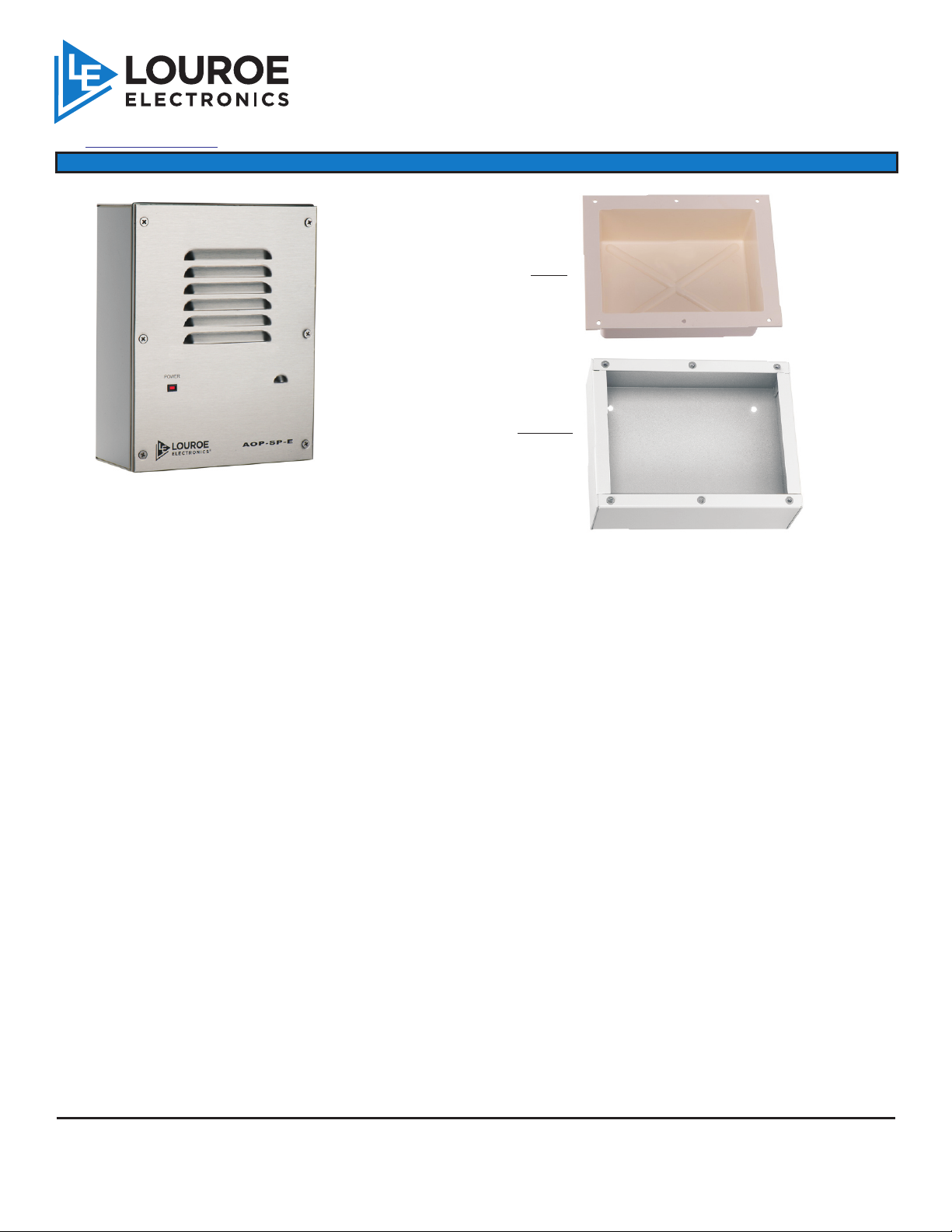
INSTALLATION AND OPERATING INSTRUCTIONS
AOP-SP-E_inst 3/15
Drill an opening top, bottom or back side
of backbox for passing wiring or for
connecting conduit.
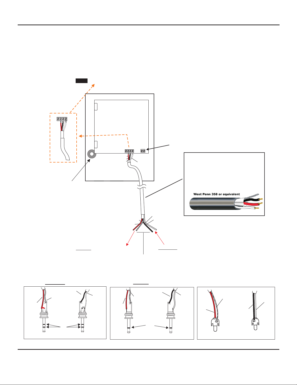
block marked A, B, C, SP
A = 12Vdc power (not used)
B = Audio output
C = Ground
SP = Speaker Connection
Bring one end of recommended cable and connect as follows:
Located on the bottom right side of PC board is a 4-pin terminal
1) Connect RED wire to terminal marked “B”
2) Connect BLACK wire to terminal marked “C” (together with bare wire)
3) Connect BARE wire to terminal marked “C“
4) Connect WHITE wire to terminal marked “SP“
5) No connection on terminal “A”
WIRING REQUIREMENTS
3 Conductor consisting of:
+
2 Conductor shielded, 20 gauge
with 22 gauge drain
+
1 Conductor unshielded, 20 gauge
All in the same jacket
WIRING CONNECTION TO IP CAMERA OR DVR
POWER CONNECTION
Bring the other end of the cable to connector that matches the audio input
and outputs of the receiving devices
1) RED (positive audio) and BARE (ground) are soldered to the audio
connector (RCA, 3.5mm Mono or Stereo plugs). This connector goes
to the Audio input of the receiving device (IP Camera, DVR, etc)
2) WHITE (positive audio) and BLACK (ground) are soldered to the another
audio connector (RCA, 3.5mm Mono or Stereo plugs. This connector
goes to the Audio output of the receiving device (IP Camera, DVR,
etc).
The unit has a 2-pin terminal block for power connections marked 12Vdc
1) Connect the positive 12Vdc of the power supply (AD-1) to the terminal
marked +
2) Connect the negative or ground of the power supply to terminal marked
GRD
WIRING CONNECTION TO AOP-SP-E
See connections on the next page