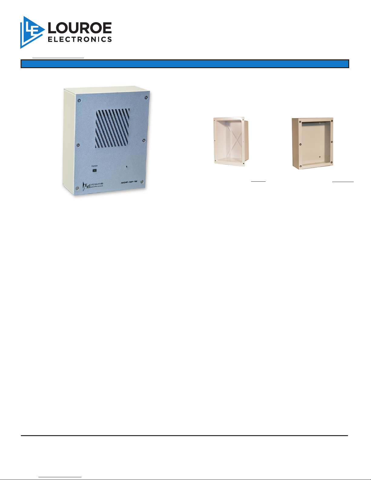
Louroe Electronics AOP-SP-W User manual

DESCRIPTION
Model AOP-SP-W is a wall mount speakerphone designed to provide 2-way audio (listen/talkback) with various modes of
audio/video transmission systems such as:
IP Camera
DVRs
Video Servers
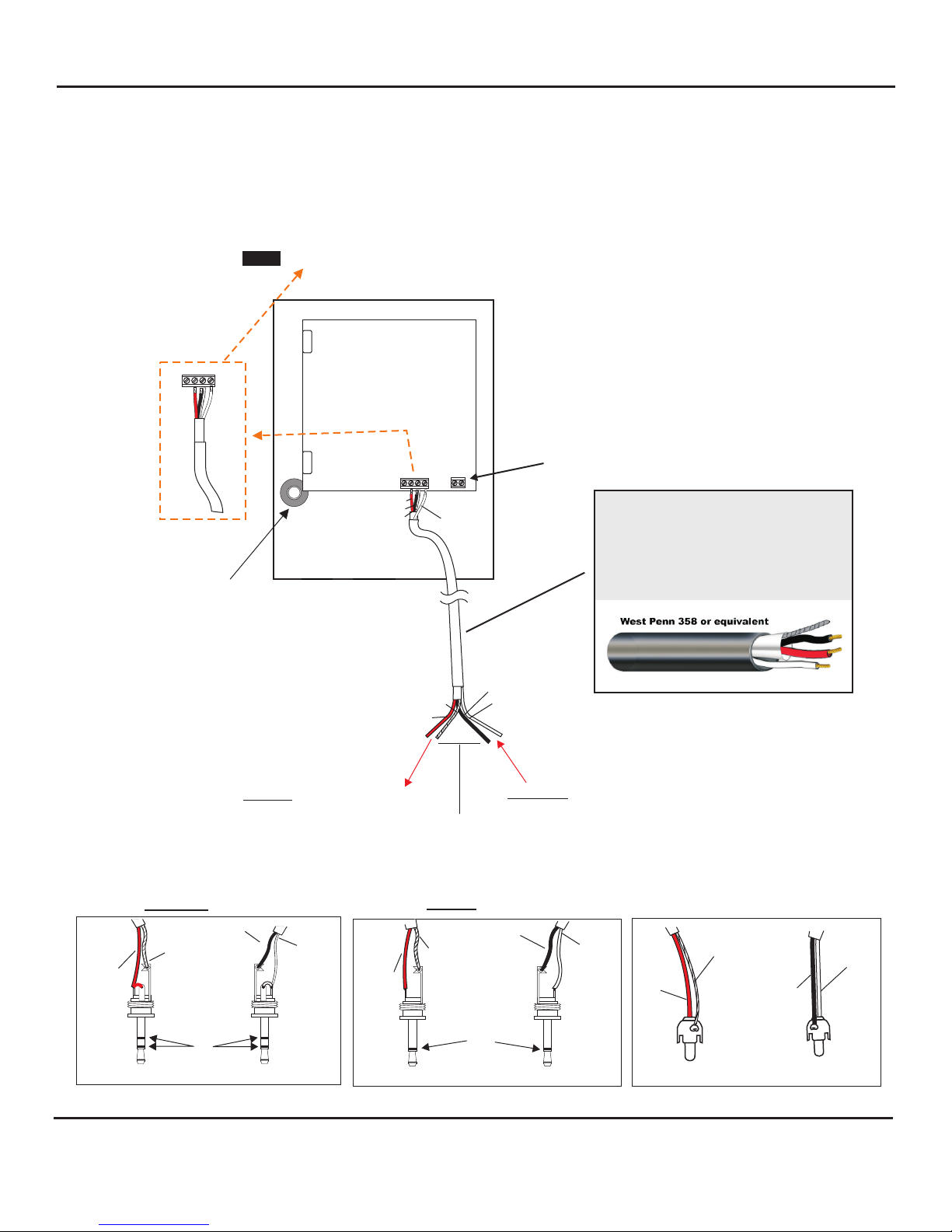
Provided with the unit are two back boxes for either flush or surface mounting to a wall. The AOP-SP-W can be used as a
stand alone unit or with companion AOP-XD. If used as a stand alone unit, the AOP-SP-W must be powered by a 12Vdc,
500mA power supply.
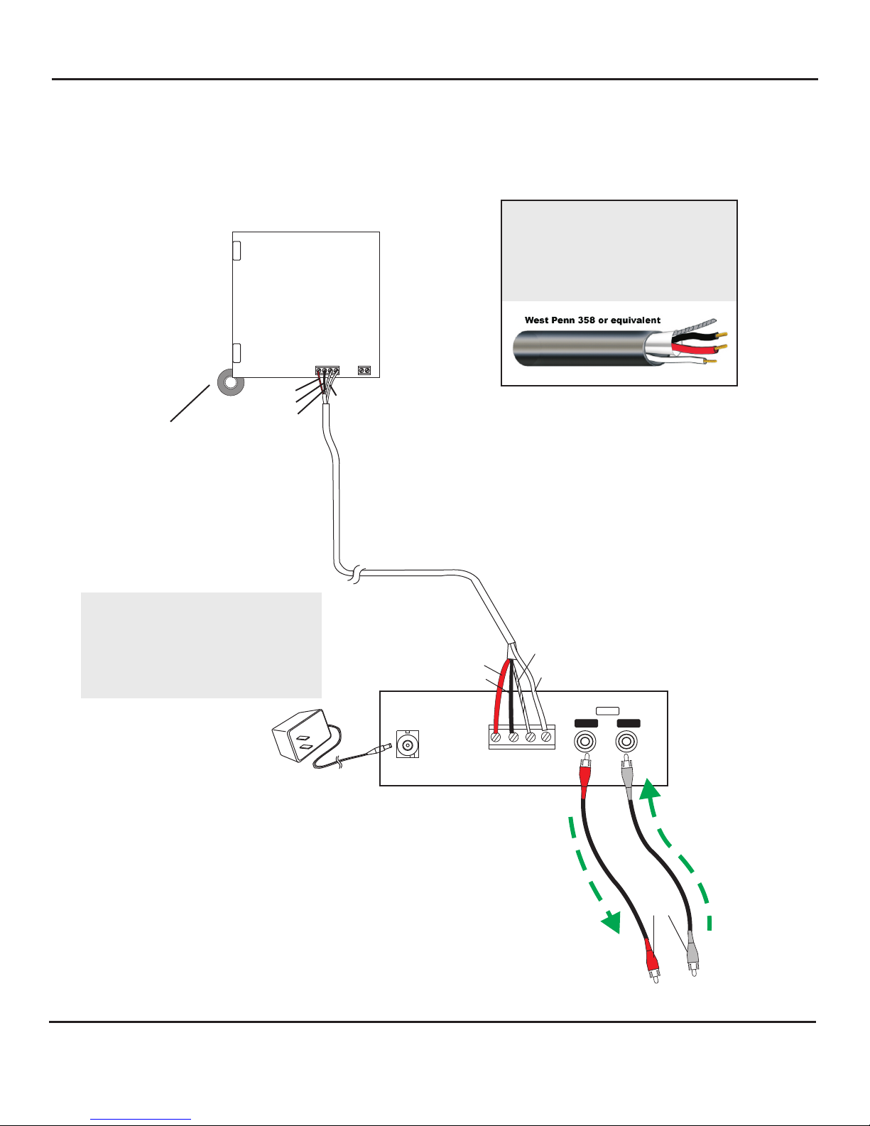
The AOP-XD Audio Transceiver unit provides two-way audio with the receiving device (IP Camera, DVR, etc). It also
provides power to the AOP-SP-W. It receives the audio signal from the audio output of the receiving device and amplifies
it before it goes to the speaker portion of the AOP-SP-W. It also drives the audio signal into the audio input of the
receiving device. The AOP-XD contains adjustable level controls for audio signals coming from the AOP-SP-W and
receiving device. Two RCA type of audio output/input jacks are provided by the AOP-XD which can be used to
accommodate most DVRs, IP Cameras, etc. audio inputs.
The gain of the microphone and speaker are factory adjusted. If it is necessary to change the gain of either or both the
audio output of the microphone and speaker of the unit, it has to be done in small increments. For adjusting the gain of the
microphone, rotate clockwise to increase or counterclockwise to decrease, the potentiometer marked “MIC” slowly until
the desired level is attained. Somebody at the head-end has to listen to it while the adjustments are made. If the
microphone’s gain is too high, it will attenuate the audio output of the speaker. The output of the speaker will then be
cutting off as you talk. If this happens, rotate the potentiometer marked “MIC” slowly counterclockwise to decrease the
gain of the microphone until the talkback sound at the speaker no longer cuts off.
To adjust the audio output of the speaker, rotate the “SPKR” potentiometer clockwise (increase) or counterclockwise
(decrease) slowly until the desired loudness is attained. If the audio from the microphone becomes attenuated, rotate the
“SPKR” potentiometer counterclockwise a small increment at a time until the microphone audio becomes louder again.
This unit has a built-in muting system that if the microphone’s adjusment (MIC) is too high it is going to mute the speaker.
Also if the speaker’s adjustment (SPKR) is too high, it’s going to mute the microphone.
OPERATIONS
Backbox (metal) for surface
mounting to wall or
flat surface
Backbox (plastic) for flush
mounting to wall or
flat surface
Page 1 of 8 aop-sp-w inst 03/11
AOP-SP-W
SPEAKERPHONE
INSTALLATION AND OPERATING INSTRUCTIONS
6955 VALJEAN AVE, VAN NUYS, CA 91406
PH: (818)994-6498 / FAX: (818)994-6458
®
LOUROE ELECTRONICS® 6 9 5 5 VA L J E A N AVENUE, VAN NUYS, CA 91406 TEL (818) 994-6498 FAX 994-6458
(818)

block marked A, B, C, SP
A = +12Vdc power (red wire)
B = Audio output of microphone
C = Ground (microphone and speaker
SP = Speaker input
Bring one end of recommended cable and connect as follows:
Located on the bottom right side of PC board is a 4-pin terminal
WIRING CONNECTION TO SPEAKER AND MICROPHONE OF AOP-SP-W
WIRING CONNECTION TO AOP-SP-W
WIRING CONNECTION FROM AOP-SP-W TO COMPANION AOP-XD
AUDIO INTERFACE UNIT
1) Connect RED wire to terminal marked “A”
2) Connect BLA CK wire to terminal marked “B”
3) Connect BARE wire to terminal marked “C“
4) Connect WHITE wire to terminal marked “SP“
Drill an opening top, bottom or back side
of backbox for passing wiring or for
connecting conduit.
The rear panel of AOP-XD has a 4 pin terminal block marked A, B, C, SP
Bring in other end and connect as follows:
1) Red wire to terminal A
2) Black wire to terminal B
3) Bare wire to terminal C
4) White wire to terminal SP
This completes the wiring between the AOP-SP-W and AOP-XD. For operation instructions and functions
regarding Model AOP-XD Transceiver Interface unit, refer to the AOP-XD instructions that accompany the unit.
Color Code of recommended wiring is:
RED - 12Vdc power to microphone
BLACK - Audio Output
BARE - Ground (microphone and speaker)
WHITE - Speaker
Color Code may vary among wire manufacturers
WIRING REQUIREMENTS
3 Conductor consisting of:
+
2 Conductor shielded, 20 gauge
with 22 gauge drain
+
1 Conductor unshielded, 20 gauge
All in the same jacket
West Penn 358 or
equivalent
Page 2 of 8
LOUROE ELECTRONICS® 6 9 5 5 VA L J E A N AVENUE, VAN NUYS, CA 91406 TEL (818) 994-6498 FAX 994-6458
(818)
INSTALLATION AND OPERATING INSTRUCTIONS
aop-sp-w inst 03/11

WHITE
BLACK
+24Vdc, 1A
BARE
RED
ABCSP
INPUT
To “Audio In” of
DVR, Video
Server, etc.
To “Audio Out” of
DVR, Video
Server, etc.
MODEL AOP-XD
AUDIO INTERFACE UNIT
(rear panel)
INTERCONNECTION DIAGRAM
BETWEEN LOUROE™MODEL AOP-SP-W
AND
AOP-XD AUDIO TRANSCEIVER INTERFACE
INPUT
AUDIO
OUTPUT
A
U
D
I
O
P
A
T
H
A
U
D
I
O
P
A
T
H
RCA Plug
Color Code of recommended wiring is:
RED - 12Vdc power to microphone
BLACK - Audio Output
BARE - Ground (microphone)
WHITE - Speaker
+24 Vdc, 1A
POWER SUPPLY
(INCLUDED)
Microphone
Connection
Terminal Block Identifier
A = 12Vdc power
B = Audio Output
C = Ground
SP = Speaker Connection
}
WIRING REQUIREMENTS
3 Conductor consisting of:
+
2 Conductor shielded, 20 gauge
with 22 gauge drain
+
1 Conductor unshielded, 20 gauge
All in the same jacket
ELECTRET
CONDENSER
MICROPHONE
RED (A)
BLACK (B)
BARE (C)
WHITE (SP)
+12Vdc
TALKBACK
ADJUST
MIC
ADJUST
C
A
SP
B
PC Board
of AOP Series
Speakerphones
Page 3 of 8
LOUROE ELECTRONICS® 6 9 5 5 VA L J E A N AVENUE, VAN NUYS, CA 91406 TEL (818) 994-6498 FAX 994-6458
(818)
INSTALLATION AND OPERATING INSTRUCTIONS
aop-sp-w inst 03/11

INTERCONNECTION DIAGRAM
CONNECTING LOUROE™MODEL AOP-SP-W
DIRECTLY TO AN IP CAMERA, DVR,
VIDEO SERVER, ETC. USING 3-COND. SHIELDED CABLE
EXT
MIC SPKR +12Vdc
AUDIO
OUT
AUDIO
IN
TALKBACK
ADJUST
MIC
ADJUST
C
A
SP
B
LOUROE™ MODEL AOP-SP-W
WHITE (SP)
BLACK (C)
(C) BARE
(B) RED
TO AUDIO OUT OF IP CAMERA, DVR, ETC.
TO AUDIO IN OF IP CAMERA, DVR, ETC.
NOTE: BLACK AND BARE WIRES ARE COMMON GROUND
4-PIN TERMINAL BLOCK IDENTIFIER OF AOP-SP-W (A,B,C,SP)
( ) B = Audio Output
( ) C = Ground (audio) and Ground (speaker) (black wire)
( ) SP = Speaker output
A = not used with this application
red
bare
white
West Penn 358
or equivalent
C
A
SP
B
WHITE (SP)
Audio Out
Audio Out Audio In
Audio In
Bare Wire
Red Wire
RCA CONNECTION
3.5mm MONO CONNECTION
3.5mm STEREO CONNECTION
White Wire
Black Wire
Black Wire
White Wire
Red Wire
Bare Wire
M
O
N
O
S
T
E
R
E
O
Audio Out
Audio In
Red Wire
Black Wire
White Wire
Bare Wire
WIRING REQUIREMENTS
3 Conductor consisting of:
+
2 Conductor shielded, 20 gauge
with 22 gauge drain
+
1 Conductor unshielded, 20 gauge
All in the same jacket
+12Vdc,500mA power required
(AD-1 power supply included)
ELECTRET
CONDENSER
MICROPHONE
AUDIO
OUT
AUDIO
IN
AOP-XD is not used for this application.
12 Vdc power is required to connect the AOP-SP-W directly to
an IP camera or DVR such as AD-1 power supply.
Positive 12Vdc connects to terminal marked “+”
Negative 12 Vdc or ground
connects to terminal marked “GND”
(wire with white stripes)
+12Vdc
+
GND
Page 4 of 8
LOUROE ELECTRONICS® 6 9 5 5 VA L J E A N AVENUE, VAN NUYS, CA 91406 TEL (818) 994-6498 FAX 994-6458
(818)
INSTALLATION AND OPERATING INSTRUCTIONS
aop-sp-w inst 03/11

IMPORTANT NOTICE
When this equipment is used as part of an audio
monitoring system, the law requires that the public be
given notice of AUDIO MONITORING ON THE
PREMISES. A decal notice is included with each
microphone shipped.
Federal Law References:
Federal Regulations, US Code, Title 18. Crime and
Criminal Procedure, Sec 2510.
SPECIFICATIONS (Microphone)
Microphone output
Type
line level (0 dB @ 1kΩ)
Electret Condenser
Supply voltage 12 Vdc, 500mA
SPECIFICATIONS (Speaker)
Speaker Power output
Speaker Impedance
Speaker magnet
Speaker size
Weight, net
2W
8Ω
3 oz. ceramic
4” (10cm)
3 Lbs. (1.4 Kg)
Microphone element sensitivity
Frequency response
Output Impedance
-45dB
40 Hz to 15 kHz 1 dB
600Ωunbalanced
SPECIFICATIONS (Mechanical)
Dimensions (Face Plate) 6 1/4"H x 8"W
Backbox for AOP-SP-W
metric (158mm H x 203mm W)
Surface Mount Box (metal) 6 1/4"H x 8"W x 2 3/4”D
Flush Mount Box (plastic)
Backbox Portion 5"H x 6 7/8"W x 2 5/8”D
Total including flange 6 1/4"H x 8"W x 2 5/8”D
metric (158mm H x 203mm W x 67mm D)
metric (127mm H x 175mm W x 67mm D)
metric (158mm H x 203mm W x 70mm D)
Page 5 of 8
LOUROE ELECTRONICS® 6 9 5 5 VA L J E A N AVENUE, VAN NUYS, CA 91406 TEL (818) 994-6498 FAX 994-6458
(818)
INSTALLATION AND OPERATING INSTRUCTIONS
aop-sp-w inst 03/11
AUDIO
MONITORING
On
These Premises
TM

NOTES
WARRANTY
LOUROE ELECTRONICS® warrants that at the time of shipment products manufactured by LOUROE ELECTRONICS® to be free of defects in material and workmanship.
Should a defect appear within one year (12 months) from date of shipment, LOUROE ELECTRONICS® will, at its sole discretion, repair or replace the defective equipment.
This equipment shall not be accepted for repair or return without prior notification by LOUROE ELECTRONICS®.
This warranty does not extend to any Louroe product that has been subjected to improper or incorrect installation, misuse, accident, or in violation of installation
instructions provided by LOUROE ELECTRONICS®.
Returned shipments to LOUROE ELECTRONICS® shall be at customer’s expense. LOUROE ELECTRONICS® will return the equipment prepaid via best way.
Page 6 of 8
LOUROE ELECTRONICS® 6 9 5 5 VA L J E A N AVENUE, VAN NUYS, CA 91406 TEL (818) 994-6498 FAX 994-6458
(818)
INSTALLATION AND OPERATING INSTRUCTIONS
aop-sp-w inst 03/11

NOTES
INSTALLATION AND OPERATING INSTRUCTIONS
Page 7 of 8
LOUROE ELECTRONICS® 6 9 5 5 VA L J E A N AVENUE, VAN NUYS, CA 91406 TEL (818) 994-6498 FAX 994-6458
(818)
aop-sp-w inst 03/11

MANUFACTURED
IN THE
Page 8 of 8
LOUROE ELECTRONICS® 6 9 5 5 VA L J E A N AVENUE, VAN NUYS, CA 91406 TEL (818) 994-6498 FAX 994-6458
(818)
INSTALLATION AND OPERATING INSTRUCTIONS
aop-sp-w inst 03/11
Table of contents
Other Louroe Electronics Telephone manuals

Louroe Electronics
Louroe Electronics AOP-535 User manual

Louroe Electronics
Louroe Electronics AOPSP-PB User manual

Louroe Electronics
Louroe Electronics AOP-SP-CF User manual

Louroe Electronics
Louroe Electronics AOP-SP-E User manual

Louroe Electronics
Louroe Electronics AOP-SP-E User manual

Louroe Electronics
Louroe Electronics AOP-550 User manual

Louroe Electronics
Louroe Electronics AOP-SP-CF User manual

Louroe Electronics
Louroe Electronics AOP-SP-W User manual

Louroe Electronics
Louroe Electronics 370 User manual