PAGE 2 OF 8
Color Code of recommended wiring is:
RED - 12Vdc power to microphone
BLACK - Audio Output
BARE - Ground (microphone)
WHITE - Speaker
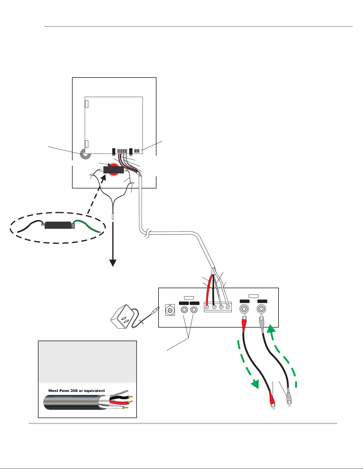
block marked A, B, C, SP
A = 12Vdc power (red wire)
B = Audio output (black wire)
C = Ground (bare wire)
SP = Speaker connection (white wire)
Bring one end of recommended cable and connect as follows:
Located on the bottom right side of PC board is a 4-pin terminal
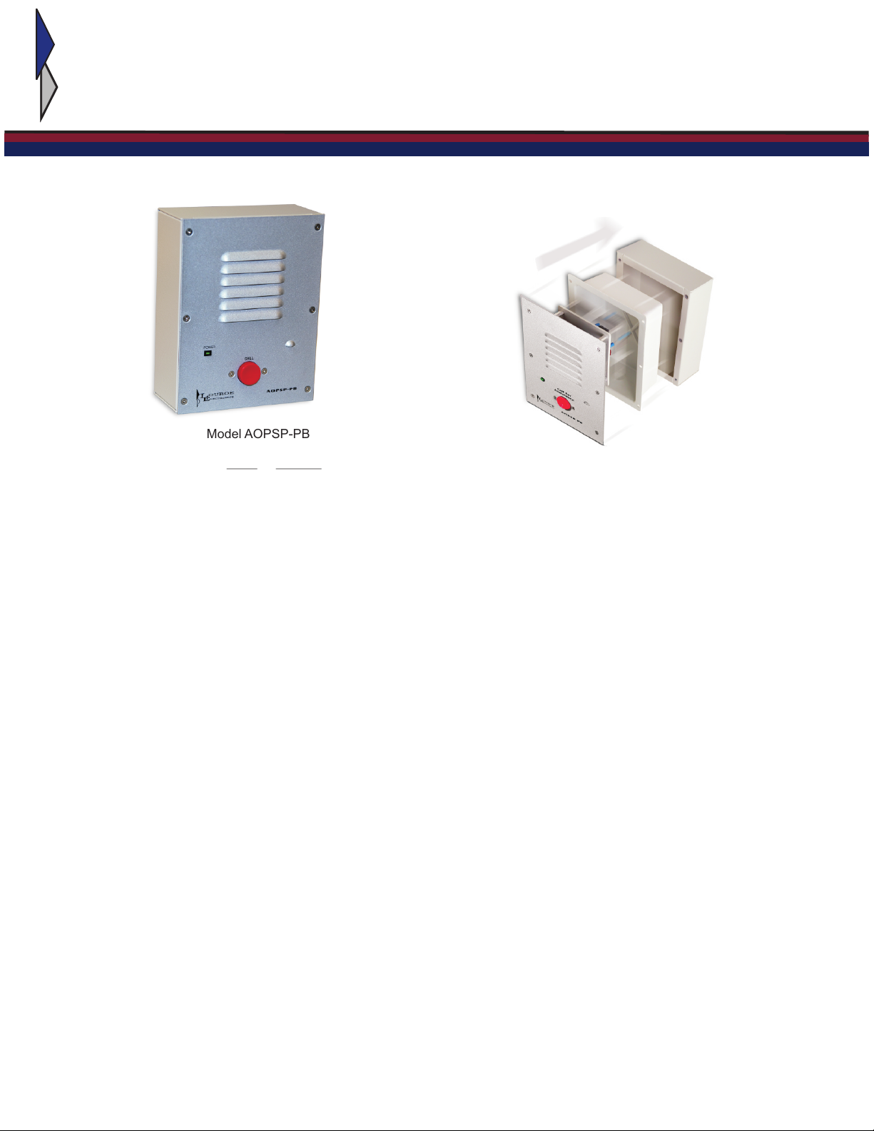
WIRING CONNECTION TO SPEAKER AND MICROPHONE OF AOPSP-PB
WIRING CONNECTION TO AOPSP-PB
WIRING CONNECTION TO MODEL AOPSP-PB’S CALL BUTTON
WIRING CONNECTION FROM AOPSP-PB TO
COMPANION AOP-XD AUDIO INTERFACE UNIT
Connect the two wires (black and green) attached to Call Button Switch to the contacts of the
receiving device, using wire nuts and 22 gauge stranded wire. Refer to the receiving device
manufacturers instructions for proper connection.
The rear panel of AOP-XD has a 4 pin terminal block marked A, B, C, SP
Bring in other end and connect as follows:
1) Red wire to terminal A
2) Black wire to terminal B
3) Bare wire to terminal C
4) White wire to terminal SP
APPLYING POWER TO MODEL AOP-XD
Included with the AOP-XD is a 24V, 1A Power Supply. First connect small end to the 24Vdc jack located on the
back panel of AOP-XD. Then plug large 2-prong power block into a standard 120V electrical outlet or power
strip. Green LED on front panel will illuminate, indicating unit is powered. Model AOP-XD will send power to the
remote AOPSP-PB Call Station. For instructions regarding the functions of AOP-XD, refer to accompanying
AOP-XD instructions.
1) Connect RED wire to terminal marked “A”
2) Connect BLA CK wire to terminal marked “B”
3) Connect BARE wire to terminal marked “C “
4) Connect WHITE wire to terminal marked “SP “
LOUROE ELECTRONICS 6 9 5 5 V AVENUE, VAN NUYS, CA 91406 TEL (818) 994-6498 FAX 994-6458
ALJEAN (818)
INSTALLATION AND OPERATING INSTRUCTIONS
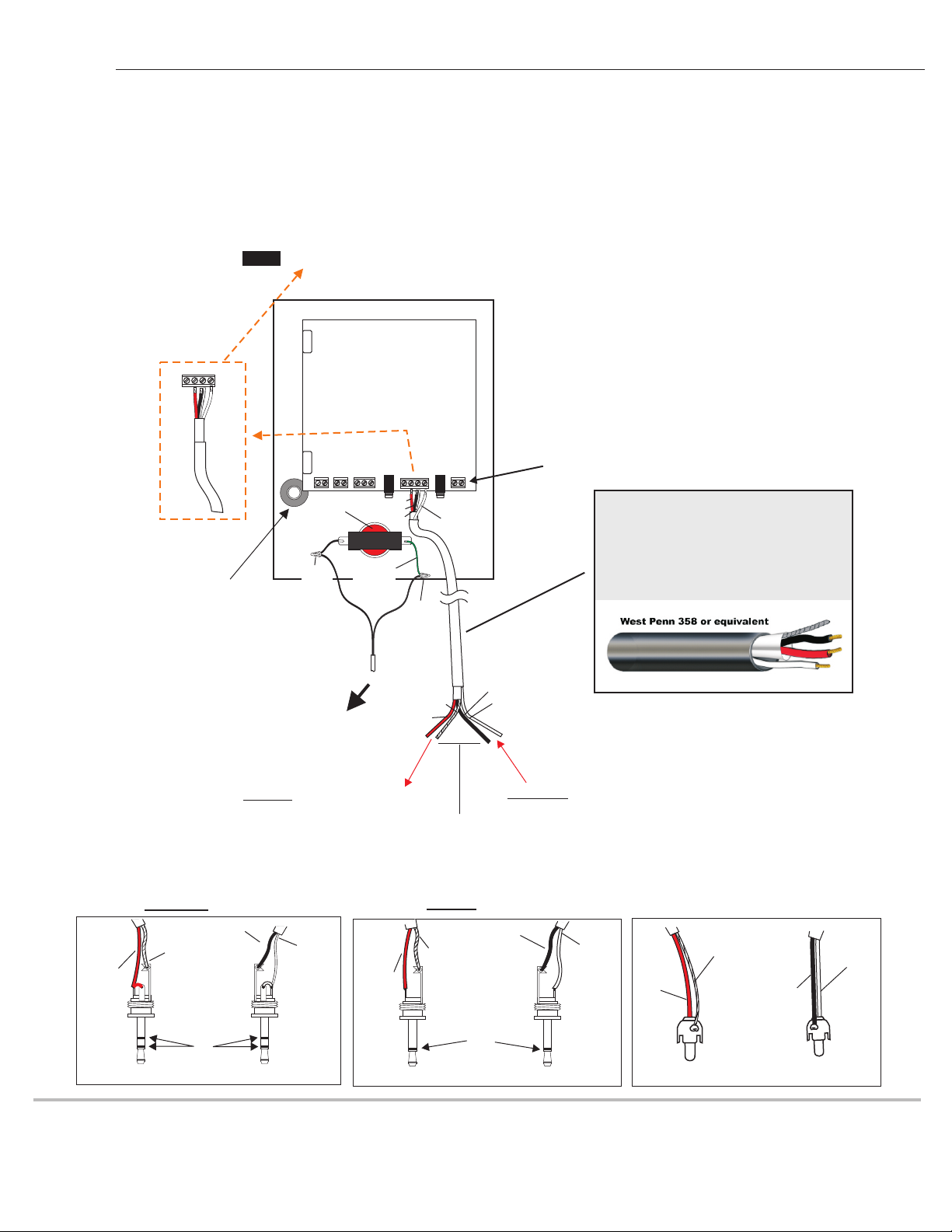
WIRING REQUIREMENTS
3 Conductor consisting of:
+
2 Conductor shielded, 20 gauge
with 22 gauge drain
+
1 Conductor unshielded, 20 gauge
All in the same jacket
aopsp-pb 8/09
Drill an opening top, bottom or
back side of backbox for
passing wiring or for connecting
conduit