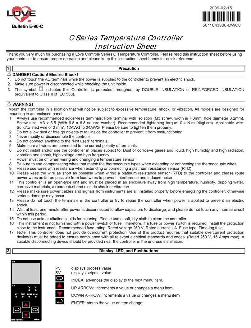
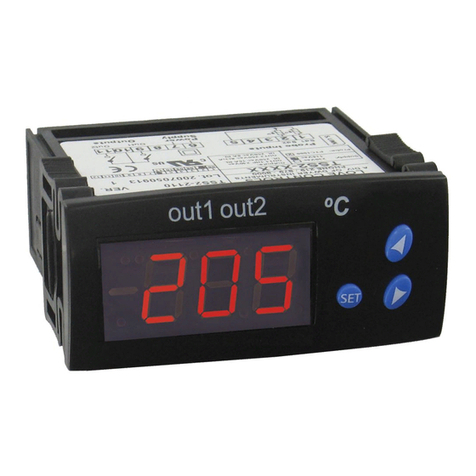
Love Controls LCU 032 User manual

Process Temperature Controller
INSTRUCTION MANUAL
LCU 032
LCu032 9/6/05 1:34 PM Page 1

LOVE CONTROLS
2
LCU032
LCU032
Built-in Fuzzy function “The Smallest Temperature Controller”
•Fuzzy
•Alarm Output
•Input Correction
• °C/°F Selectable
• Universal Input-Output
• Output Limits
• IP65 Front Facia
• Interface (RS485)
• Heating / Cooling
• Auto Tuning (Standard,
Low PV type)
Features
Model: LCU032
LCu032 9/6/05 1:34 PM Page 2

3
LCu032 9/6/05 1:34 PM Page 3

CONTENTS
1. SAFETY INFORMATION . . . . . . . . . . . . . . . . . . . . . . . . .P.5
2. INSTRUCTION . . . . . . . . . . . . . . . . . . . . . . . . . . . . . . . . .P.7
3. MODELS & SUFFIX CODE . . . . . . . . . . . . . . . . . . . . . . .P.7
4. DIMENSIONS & PANEL CUTOUT . . . . . . . . . . . . . . . . . .P.7
5. INPUT & OUTPUT . . . . . . . . . . . . . . . . . . . . . . . . . . . . . .P.8
6. OPERATION . . . . . . . . . . . . . . . . . . . . . . . . . . . . . . . . . . .P.9
7. DISPLAY & PARAMETER . . . . . . . . . . . . . . . . . . . . . . . .P.10
8. PARAMETER SETTING . . . . . . . . . . . . . . . . . . . . . . . . .P.11
9. SETTING MODE . . . . . . . . . . . . . . . . . . . . . . . . . . . . . . .P.12
10. SPECIFICATION . . . . . . . . . . . . . . . . . . . . . . . . . . . . . .P.17
11. ALARM TYPE AND CODE . . . . . . . . . . . . . . . . . . . . . .P.21
LOVE CONTROLS
4
LCu032 9/6/05 1:34 PM Page 4

Before using, please read this (SAFETY INFORMATION) and then this controller.
It is most important that the instructions in this manual are followed when using this instrument.
Please keep this manual for future reference.
Precautions are classified in WARNING and CAUTION.
5
WARNING There is a possibility of death or heavy injury when handling in wrong way.
CAUTION There is a possibility of injury or physical damage when handling in wrong way.
WARNING
1 Caution on wiring
•Use an external protection circuit if a fault in the control loop could possibly lead to a serious prob-
lem.
2 Power supply
•Afuse is fitted inside the instrument. (Fuse rating 250V, 1A)
•Use a rated voltage to prevent damage or trouble.
• To avoid electrical shock or damage, do not turn ON the power until the wiring is completed.
3 Prohibit use in gas atmosphere
Do not use it at a place exposed to combustible or explosive gas.
4 Handling of unit
•To avoid malfunction, electrical shock or fire, this unit must not be disassembled or repaired.
•Do not touch the terminals to avoid electrical shock or malfunction.
5 Caution on maintenance
•Turn OFF the power before mounting or removing the instrument.
•To ensure continuous and safe operation of the instrument, periodical maintenance is recommend-
ed. Some parts are limited in life.
•The warranty period is 1 year only if using in the correct way.
CAUTION
1 Caution on handling
Do not install the instrument under any of the following conditions.
•The ambient temperature exceeds 0 ~ 50°C
•The ambient humidity exceeds 20 ~ 90%RH.
•Aplace where temperature changes suddenly or icing occurs.
•Aplace exposed to corrosive gas or combustible gas.
•Vibration or shock is likely to be transmitted to the instrument.
•Aplace exposed to water, oil, chemicals, steam, sunlight.
•Aplace exposed to much dust, salt or iron.
•Aplace with much inductive disturbance, static electricity, magnetism noise.
•Aplace where heat such as radiant heat stays.
SAFETY INFORMATION
1
LCu032 9/6/05 1:34 PM Page 5

2 Installation
•Attach the brackets (2 units) on the fixed halls and tighten with a screwdriver. Fixing torque is about
14.7N. cm (1.5kg.cm) (Care should be taken not to tighten forcedly.)
3 Caution on terminal connections
•Use a compensating cable with thermocouple.
•For R.T.D input use a cable which is a small lead wire resistance and without resistance difference to
3wires.
•If the wiring has noise, use the following step: connect a surge absorber to the conductor coil side if
the conductors are connected to the load output, such as the relay contact output.
•Use an insulating transformer with a noise filter when the power supply has much noise.
•Noise filter should be mounted on a panel which has been earthed and the wiring between the noise
filter output and the instrument power terminals should be shorten.
•It is effective to use a twisted cable for power supply against noise.
•The heater power supply and the instrument power supply should be connected using the same
power supply when a heater break alarm.
•Time for preparation of contact output is required at power ON. When the output signal is used for
an external interlock circuit, connect a delay relay.
4 Other
•Do not use organic solvents such as alcohol, benzine when cleaning. (Use neutral detergent)
5 Caution on key operation / trouble
•If alarm function is not set correctly, alarm output can not be operated at a trouble.
Be sure to check the alarm operation.
•If the input cable is disconnected, the display shows “ boUt”.
When replacing the sensor, please turn OFF the power supply
CAUTION
1 For connection
• To avoid inductive noise to input wires separate from the power and output wires.
• Keep input wires away from output wires and use shielded wires.
2 For load circuit connection
•Use an extra relay when the frequency of operation is rather high. In this case, SSR output type is
Recommended.
• Electromagnetic switch : Proportional cycle time is Min. 30 sec
• SSR : Proportional cycle time is Min. 1 sec
• Contact output life : Mechanical : Min. 10 million times (no load)
Electrical : Min. 100 thousand times (rated load)
• SSR drive pulse voltage, DC 4~20mA are not insulated with internal circuit.
Use non-grounded sensor to R.T.D and thermocouple.
3 For waterproof (Waterproof type)
The instrument has IP65. Use rubber packing when installing the instrument to panel.
Please attach the rubber in correct way.
6
LCu032 9/6/05 1:34 PM Page 6

INSTRUCTION
LCU032-
Process Temperature Controller DIN48 x 24 mm (1/32 DIN)
Control type 0 : Universal
1 : Heating / Cooling
Optional 0 : None
1 : RS485
7
This instrument has process-value (PV) and set-value (SV) each 4 digits with 7 segment FND. This
instrument is divided Universal type and heating-cooling type and each setting items has 10 groups.
Function and feature : Group P.I.D, Universal-input (19 types), Universal-output (Relay, SSR, Current),
Local input, Remote input, External contact input, Ramp function, Auto-tuning 2 types (standard type,
low PV type), Retransmission, Communication (RS485 /422), Power supply for sensor, 20 types of
alarm, Sampling cycle 250ms, ¸±0.5% of FS high accuracy.
2
MODEL & SUFFIX CODE
3
DIMENSIONS & PANEL CUTOUT
4
LCu032 9/6/05 1:34 PM Page 7

8
INPUT & OUTPUT
5
LCu032 9/6/05 1:34 PM Page 8

9
OPERATION
6
LCu032 9/6/05 1:34 PM Page 9

10
DISPLAY & PARAMETER
7
LCU032 Temperature Controller has three screens: “Operation Screen”, “Menu Screen”, and “Group
Indication Level Selection Screen.”
Menu Screen is composed of each group; therefore, concerned parameters can be grasped at a
glance. It is the simplest and safest design for users.
Parameters should be set in order of “Input Group > Output Group > Other Group.”
Input Group and Output Group must be set first since the parameters affect other groups.
This Controllers Group Indication Level Mode ( LEHL) has three levels from Level 1 to Level 3.
Level 1 is composed of the groups which users frequently modify and check during operation.
Level 2 adds enhanced features for more convenient use of the Controller to Level 1.
Level 3 adds the groups for setting the Controller to Level 2; and is composed of the parameters which
are set only one time in the first setting.
• The above-mentioned items do not apply to indicator.
• Groups Shown Per Display (DISP)
DISP
1
2
3
GROUP INDICATION LEVEL
G.CTL
G.CTL, G.AT, G.PID, G.ALM, G.TRN, G.COM
G.CTL, G.AT, G.PID, G.ALM, G.TRN, G.COM, G.OUT, G.IN
LCu032 9/6/05 1:34 PM Page 10

11
PARAMETER SETTING
8
LCu032 9/6/05 1:34 PM Page 11

12
SETTING MODE
9
LCu032 9/6/05 1:34 PM Page 12

13
1 SETTING AND DISPLAY LEVEL (dISP)
This controller has 3 different levels of setting, there by restricting operator access if so desired.
The following describes these levels;
Level 1: Access available to setting and displaying only up Group #3 (Group Set value)
Level 2: Access available to setting and displaying only up Group #9 (Group Communication)
Level 3: Access available to setting and displaying of all Groups.
2 CONTROL GROUP (GCtL)
1. Set SV for temperature control.
2. Fuzzy function is selectable (Fuzzy function is operating in the PID control.)
3 AUTO TUNING GROUP (GAt)
1. This controller has two type of auto tuning a STD (Standard type) and Low PV type (SV-10%).
2. Auto tuning is starting when auto tuning selection is ON.
*1: Starting auto tuning at SV-10% of Max. range.
LCu032 9/6/05 1:34 PM Page 13

14
LCu032 9/6/05 1:34 PM Page 14

15
LCu032 9/6/05 1:34 PM Page 15

16
LCu032 9/6/05 1:34 PM Page 16

17
SPECIFICATIONS
10
Input
Sampling time
Input resolution
Input impedance
Lead wire tolerable resistance
Input tolerable voltage
Noise removal rate
Standard
Standard junction temp.
compensation tolerance
Burn-out
Accuracy
Input range
Thermocouple: K, J, E, T, R, S, B, L, N, U, WRe 5-26, PL-11
R.T.D.: Pt 100Ω, KPt 100Ω
Direct voltage: 1-5V, -10-20mV, 0-100mV (Free scale type)
250mS
Below decimal point of measurement range
T/C and mV input: 1MΩmin., DC V: 1MΩ
R.T.D. 10Ωmax. / wire
±10V (T/C, R.T.D., Voltage: mV DC)
±20V (Voltage: V DC)
NMRR (normal mode): 40dB min.
CMRR (common mode): 120dB min. (50/60 Hz ±1%)
T/C, R.T.D: KS, IEC, DIN
±1.5°C (15-35°C), ±2.0°C (0-50°C)
T/C: Off, Up/Down scale selectable
R.T.D: Off, Up/Down scale selectable (Detection current: 50nA)
±0.5% (Full Scale)
Refer to “Input signal and Measurement range”
T/C and R.T.D are changeable within range of input signal and
measurement range.
Voltage: Min. voltage and max. voltage are available within range of
measurement.
Scaling available
1) INPUT
Relay
contact output
Contact capacity: 240VAC 1A, 30V DC 1A (resistive load)
Contact: 1a
Output points: Refer to “Terminal Arrangement”
Current output Current output range: 4-20 mA DC
Resistive load: 600Ωmax.
Accuracy: ±0.5% of max. scale (4-20mA range)
Resolution: Approx. 3,000
Output ripple: 0.3% (P-P)max of scale (150Hz)
Sampling: 250mS
2) OUTPUT
1. ALARM (Terminal no. 6 -7)
2. RETRANSMISSION OUTPUT (Terminal no. 4 - 5)
LCu032 9/6/05 1:34 PM Page 17

18
Relay
contact output
SSR drive
voltage output
Current output
Contact capacity: 240VAC 1A, 30VDC 1A (resistive load)
Contact: 1a
Output operation: P.I.D control, ON/OFF
Proportional cycle: 1-1000 sec.
Output limit: 0.0 - 100.0% range, higher limit (OH) or lower limit (OL)
selectable
ON/OFF hysteresis: 0-100% (Full scale)
Time resolution: 0.1% or 10mS
ON voltage: 24VDC min. (resistive load 600Ωmin., 30mA limit when
short)
OFF voltage: 0.1 VDC max.
Proportional cycle: 1-1000 sec.
Output operation: P.I.D. control
Output limit: 0.0-100.0% range, higher limit (OH) or lower limit (OL)
selectable
Time resolution: 0.1% or 10mS
Current output range: 4-20mA DC
resistive load: 600Ωmax.
Accuracy: ±0.5% of full scale (4-20mA range), Resolution: Approx.
3,000
Output ripple: 0.3% (P-P) of max. scale (150Hz)
Sampling time: 250mS
Output operation: P.I.D control
Output limit: -5.0-105.0% range, higher limit(OH) or lower limit(OL)
selectable
3. CONTROL OUTPUT
Power supply
Frequency
Power consumption
Insulation resistance
Dielectric strength
100-240VAC (90-264VAC)
50/60HZ
6.0W max., 10VA max.
Between primary terminal and secondary terminal: DC 500V, 20MΩmin.
Between primary terminal and ground: DC 500V, 20Ωmin.
Between ground and secondary terminal: DC 500V, 20MΩmin.
Between primary terminal and secondary terminal: 2,300VAC 50/60 Hz for 1 min.
Between primary terminal and secondary terminal: 2,300VAC 50/60Hz for 1 min.
Between primary terminal and ground: 2,300VAC 50/60Hz for 1 min.
Between F-G and secondary terminal: 1,500VAC 50/60Hz for 1 min.
3) POWER SUPPLY
LCu032 9/6/05 1:34 PM Page 18

19
Measurement Input
Control
Retransmission
Output
Alarm Output
Input correction (Bias): -100.0-100.0% for instrument range
Scaling: According to SH, Sl of measurement range
Filter: Off, 1-120 sec.
3 settings (SV1, SV2 and SV3) and P.I.D setting each
Auto tuning: According to set value (Standard type, Low PV type)
Proportional Band: 0.-999.9% (Max. range), 0.0-999.9% (When heating-cooling
control)
Integral Time: OFF, 1-6000 sec.
Derivative Time: OFF, 1-6000 sec.
ON/OFF control: By selecting output code (OT)”O”
P. I.D selection: Zone PID/Segment PID selectable
Manual Reset: -5.0-105.0% of output value, 0.0-105.0% when heating, cooling
control
ON/OFF hysteresis (HYS): 0.0-100.0% of instrument range (valid when ON/OFF
control)
Heating-Cooling Hysteresis: -100.0-50.0% of output value
A.R.W (Anit Reset Wind-up): AUTO, 50.0-200.0%
Fuzzy: Selection ON/OFF by parameter
Signal: Process value (PV), Set value (SV), Output value (MV)
Scaling: PV, SV
Set point: 1 Point (1a)
Multi-alarm: High/Low process alarm, High/Low deviation alarm, Hold function of
alarm, Heater break alarm (H.B.A)
Setting range: Process alarm.......0-100% of instrument range
Deviation alarm.......-100-100% of instrument range
Alarm hysteresis: 0.0-100.0% of instrument range
4) FUNCTION
Installation
environment
Normal operation
condition
Influence of ambient
temperature
Continuous vibration (5-14 Hz): forward width 1.2mm max.
(4-150Hz): 4.9m/s2(0.5G) max.
Vibration: 14.7m/s2(1.5G), 15 sec. max (each 3 direction)
Shock: 147m/s2(15G) 11 msec max. (6 direction each 3 times)
Panel cutout: Page 7
Ambient temperature: 0-50°C
Ambient humidity: 20-90%RH (no condensation)
Influence of magnetic: 400AT/m max.
Warm-up time: 30 min. min.
T/C, Voltage input: ±1µV/°C or ±0.01%/°C of max. range
R.T.D input: ±0.05Ω/°C max.
Analog output: ±0.05%/°C max. (continuous output)
5) OPERATING ENVIRONMENT
LCu032 9/6/05 1:34 PM Page 19

20
Storage temperature
Storage humidity
Shock
-25-70°C
5-95% RH (no condensation)
1m max. in packing condition
6) STORAGE CONDITION
Model
LCU032
External Dimension
48 (W) x 26 (H) x 100 (D) mm
7) STRUCTURE
Protection
IP 65 front facia
Weight
94g
Material
Plastic case (ABS)
Safety standard
EMC
UL 508 (Approval expected)
CSA 1010 (Approval expected)
EN 61010 (Under inspecting)
EMI, EMS (Under inspecting)
8) SAFETY AND EMC STANDARD
Standard
Communication address
Communication method
Synchronization
Communication sequence
Communication distance
Communication speed
Start bit
Data bit
Parity bit
Stop bit
Communication protocol
Response time
EIA RS 485
0-31, 1-99 setting available
2 wire half duplex or 4 wire half duplex
Start-stop synchronous mode
None
1.2 Km max.
600, 1200, 2400, 4800, 9600 BPS (Speed is changeable by parameter)
1 BIT
7 or 8 BIT
None, even numbers, odd numbers
1 or 2 BIT
PC LINK WITHOUT SUM(0), PC LINK WITH SUM (1)
Reception treatment time + (Response time x 10mS)
9) INTERFACE
LCu032 9/6/05 1:34 PM Page 20
Table of contents
Other Love Controls Temperature Controllers manuals
Popular Temperature Controllers manuals by other brands

Delta
Delta DTB4824 instruction sheet

HYDACELECTRONIC
HYDACELECTRONIC ETS 4100S Operation manual

Fantini Cosmi
Fantini Cosmi CH180K2 Instructions for use

AutomationDirect
AutomationDirect SOLO SL4848 Series quick start guide

Samwontech
Samwontech SU-105DA-N user manual

Tek-Trol
Tek-Trol Tek-LCD 7802A instruction manual

Chino
Chino TP-L0260EN instruction manual

S+S Regeltechnik
S+S Regeltechnik Thermasreg RTR-S Series Operating Instructions, Mounting & Installation

Elesta
Elesta DOMOTESTA RDO353A series user manual

DELTA DORE
DELTA DORE TYBOX 117 Important product information

Siemens
Siemens Free Energy Band RCU61U Technical instructions

Bergstrom
Bergstrom NITE Kenworth T680 installation manual