Bergstrom NITE Kenworth T680 User manual

1
Installation Manual
Kenworth T680
without factory installed heater
For Phoenix Gen 4 units built after 6/26/2017
2390 Blackhawk Road ● Rockford, IL 61109 ● www.nitesystem.com ● 1-866-204-8570
The information contained herein is proprietary to Bergstrom Inc and/or its subsidiaries shall
not be reproduced, copied, or disclosed in whole or in part, or used for manufacture or any
other purpose, without prior written permission of Bergstrom Inc. The only controlled version
is that viewed electronically on the designated Bergstrom intranet site.

2
Table of Contents
1-1
1-2
1-7
1-8
1-9
1-10
2-1
3-1
4-1
5-1
6-1
7-1
Refrigerant Charging
Battery Management
Operating Instructions
Wiring Diagrams
Espar Heater Install
Electrical Installation
Installation Procedures
Tools Required
Before You Start / EPA
Introduction
Unit Exploded View
Warranty / Website

3
1-1
Congratulations. You have chosen
the premier no-idle climate control
system on the market today—the
NITE®Phoenix from Bergstrom.
The NITE Phoenix is a powerful 12V
rechargeable DC system that keeps
sleeper compartments cool in hot
weather and warm in cold weather
(with optional heater) without having to
idle the truck’s engine—and without a
genset. It not only dramatically
reduces fuel burned, it’s also very
environmentally friendly.
Your NITE Phoenix is a self-
contained, hermetically sealed,
compact A/C system that produces
approximately 7,500 BTU/h and has
been quality engineered for years of
reliable service. The system
operates independently from your
truck’s engine using its own deep
cycle batteries that are completely
separated from the truck’s starting
batteries.
The deep cycle batteries used are
the most advanced ever—and will
efficiently power the system for 7 to
9 hours. The batteries are then fully
recharged after just 4 to 6 hours of
driving.
Add it all up, and you have a
revolutionary no-idle system that will
save you money and fuel year after
year—the NITE Phoenix from
Bergstrom.
NOTE:
The NITE Phoenix A/C system is
designed to maintain a comfortable
temperature inside the sleeper
without running the engine.
For optimal comfort, the curtain
between the cab and the sleeper
must be closed when using the unit.
To enhance cooling efficiency during
the day, solar reflectors or curtains
should be placed over windshield and
all windows to block sunlight from
entering the cab and sleeper.
The NITE Phoenix A/C unit will not
pull down a hot sleeper that has
been sitting in the sun without the
factory A/C running. To assist the
NITE Phoenix unit in cooling down
the sleeper, start the engine and run
the factory A/C until desired
temperature is reached. The NITE
Phoenix unit will then maintain a
comfortable temperature depending
on solar load & ambient
temperature.
Introduction

4
Before You Start / EPA
1-2
A typical installation of the NITE Phoenix
generally takes between 8 to 10 hours,
although your particular situation may vary.
This manual contains step-by- step installation
instructions. It is divided into three categories:
●General installation
●Electrical installation
●Heater installation(optional)
There is also a section on how to check your
NITE Phoenix to make sure the installation
was successful, and a section on how to
operate your NITE Phoenix.
If relocation or reinstallation of any pre-
installed equipment is necessary for
installation of the NITE Phoenix equipment -
please refer to the components manufacturer's
instructions or safety guidelines for proper
installation.
Before you start, we highly recommend doing
the following to help make your installation as
easy as possible.
1. Lay out all parts and check to make sure you
have all parts listed on the parts list.
Depending on truck, some hardware may
not be used. If you are missing any parts,
please call 1-866-204-8570.
2. To prevent damage to compressor, keep the
NITE Phoenix unit in an upright position at all
times. If unit is tipped, place back in upright
position for a minimum of 6 hours prior to
running.
3. Check the list of tools needed for installation
and make sure you have all of them. Keep all
tools within easyreach.
4. Look through the whole installation manual to
get an understanding of the order in which
components are installed.
5. Make sure you have good lighting and
enough space to work in.
6. You may want to get an assistant to help
you to reduce the number of times you have
to climb in and out of the cab.
7. Make sure you wear all appropriate safety
equipment
Photo above is representative of kit
1000230792 only.

5
NOTICE - Prior to installation:
Installation, service, and repair of these units should be solicited
only by trained service technicians who are acquainted with
standard service instructions and training material.
All equipment should be installed in accordance with accepted
principles and unit installation instructions. Extreme caution
should be observed when troubleshooting electrical
components. These messages are for your protection and
information. Failure to follow these alerted messages may
cause bodily injuries to yourself and/or others as well as
damages to the specified unit.
Health, Safety, and Environmental Policy
Under any condition Bergstrom Inc. is committed to protecting
the health and safety of all working individuals at or visiting our
site. We strategize, administer, conduct, and supervise our
efforts in agreement with best practice. Hence, we want to
ensure all workers have a clear understanding of their
accountabilities with that of the company.
Environmental Concerns
Public awareness of and education about the benefits of using
green technologies, coupled with energy efficiency, has created
renewed interest within the HVAC industry.
When materials are discarded attempt to reclaim and recycle
them. To preserve our environment, follow appropriate rules
and regulations when disposing of any resources. It is under our
obligation to put in place a series of practices and procedures
that, when taken together, result in an environmental
management system.
Disclaimer of Liability
Descriptions and specifications within this manual were in effect
at the time of production. Models and specifications are subject
to change.
Refer to nitesystem.com for more information, or contact
customer service at 866.204.8570.
1-3
Picture Symbols
Observe all warning and caution notices posted on
equipment and in instructions and/or manuals. Pay
special attention to directives prefixed by symbols and
signals indicated as “Warning”, “Caution”, and “Note”.
Do not disregard any of these alerts.
Warning
This picture symbol with the remark “Warning” refers
to the risk of imminent danger and can be vital to
one’s health. The message will convey what the
hazards are, results when warnings are not heed to,
and/or how to avoid such injury. Under certain
circumstances, failure to comply with these
instructions can cause severe or life-threatening
impairment.
Caution
This picture symbol with the remark “Caution” refers
to a hazardous situation for a person and/or the
product. Failure to comply with these instructions can
cause bodily injuries to yourself and/or others as well
as damage to machinery.
Note
This picture symbol with the remark “Note” contains
information for use and helpful tips to assist an
individual when repairing a specified unit or vehicle.
Before You Start / EPA
6
Precautions for working with HFC134a
(R134a) Refrigerant and Polyvinyl Ether
(PVE) Refrigerant Oil
WARNING
Do not breath A/C refrigerant, oil vapor, or
mist. Exposure may cause irritation to the
eyes, nose, and throat.
Instances where there are accidental system
discharges; ventilate work area before
resuming service.
For additional health and safety information
contact the refrigerant and oil manufactures.
CAUTION
The air conditioning system uses
HFC134a (R134a) refrigerant and
polyvinyl ether (PVE) refrigerant oil,
which are not compatible with CFC-12
(R12) refrigerant, mineral oil, or PAG oil. If
the refrigerants or oils are mixed, the
compressor may fail.
Do not attempt to use R-12 servicing
equipment. Failure to follow this statement
may result in personal injury or equipment
damages.
Use service equipment that is only U.L listed
and certified in which meets the required
standards of SAE J2210 to remove
HFC134a (R134a) from the air condition
system.
Before testing, please authenticate the
HFC134a (R134a) refrigerant in the vehicle
system and recycling equipment / recovery
tank are contaminate free by using a
refrigerant identifier.
Note
All equipment must be serviced by
trained personnel only.
R134a service equipment and/or vehicle air
conditioning systems should not be pressure or
leak tested with compressed air.
Air conditioning system may consist of
R134a fluorescent dye to determine leak
detection. Examine with a high intensity
ultraviolet light system.
Specified labels on unit will identify systems
that contain fluorescent dye.
1-4
Note
The air conditioning system is designed only for
certain polyvinyl ether (PVE) refrigerant oil for
HFC134a (R134a) A/C systems and HFC134a
(R134a) components. The only recommended oil for
this particular system is Idemitsu FVC68D PVE oil.
The PVE oil is very hygroscopic, meaning it absorbs
water. Without appropriate sealing, the oil will become
moisture saturated and should not be used.
Note
Follow the handling procedures listed below:
Only use the specified FVC68D PVE oil from a
sealed container.
After use, immediately reseal containers of oil.
To avoid contamination, do not return oil to
original container once it has been dispensed.
Additionally, never combine oil with other
refrigerant oils.
Do not allow PVE oil to come in contact with
styrofoam parts. In such occurrences, damage
may result.
Do not allow PVE oil in contact with vehicle
paint. In such occurrences, damage may result.
In order to diminish the amount of moisture that
enters the system, any connection in the
refrigerant loop that is open must be closed as
soon as possible.
.
It is recommended for components that are
replaced to have dust caps left in place until the
component is ready to be installed in the
refrigerant loop.
Once components are removed from the
refrigerant loop they should have dust caps in
place as soon as possible in order to limit and
minimize moisture intrusion.
Before You Start / EPA

7
Important Safety Notices
Before proceeding please read and understand all safety
precautions and warnings. The list as follows contains the
general safety provisions that must be followed.
Work areas should be dry, well lit, ventilated, and free of
clutter such as loose tools, parts, ignition sources and
hazardous substances. All personnel must be aware of
hazardous conditions that can coexist.
Wear protective shoes when working. Opened toed
shoes are not allowed.
Rotating parts can cause cuts, mutilation, or
strangulation. Be alert at all times when operating
machinery.
When working, do not wear loose-fitting or torn clothing.
Additionally, do not wear jewelry. These are hazards
that may cause personal injury.
Before beginning any repairs, disconnect the battery
(negative [-] cable) from both battery boxes and
discharge any capacitors.
To prevent accidental engine starting disconnect the air
starting motor, if equipped.
To prevent personal injury or harm to the specified unit
place a “do not operate” tag in the operator’s
compartment or on the controls.
Before operating, allow the engine to cool.
Always use blocks or proper stands to support the
vehicle or vehicle components before executing service
repairs. It is important that one does not operate on
anything that is supported only by lifting jacks or a hoist.
To reduce the probability of personal injury, use a hoist
or get assistance when lifting components that weigh 23
kg [50 lbs.] or more. Make certain all lifting devices such
as chains, hooks, or slings are in good condition and are
of the correct load capacity. Furthermore, all lifting
devices must be positioned correctly. When needed,
always use a spreader bar. Also, lifting hooks must not
be side-loaded.
1-5
When handling corrosion inhibitors and lubricating
oils avoid exposure to eyes and repeated contact
to skin for they may contain alkali. In case of
contact, immediately wash skin with soap and
water. When cases are severe, please contact a
physician. Store toxic products and substances
out of reach of children.
Naptha and Methyl Ethyl Ketone (MEK) are
flammable and hazardous materials and must be
used with attentiveness. Follow manufacture
guidelines to ensure safety when handling
materials. Store toxic products and substances
out of reach of children.
When operating on a vehicle be attentive and
cautious for hot parts on systems that have been
turned off, exhaust gas flow, and hot fluids in lines,
tubs, and compartments. Direct contact to skin
may cause severe burns.
Always use tools that are in good working
condition. Service technicians must be trained and
have proper understanding on how to use the tools
before administering service.
When replacing items use the same and/or
equivalent fastener part number at all times.
Conversely, do not use a fastener of reduced
quality if replacement is needed.
To prevent bodily injury or harm do not perform
any repairs when impaired, fatigued or after
consuming alcohol or drugs that can impair one’s
functioning.
According to several states and federal agencies
within the United States of America it has been
evident that used engine oil can be carcinogenic,
causing reproductive toxicity. That being said,
avoid inhalation of vapors, ingestion, and
prolonged contact with used engine oil.
Be mindful that liquefied petroleum gas is denser
than air and can accumulate near the floor, in
slumps, and low-lying area.
Close the manual fuel valves prior to performing
maintenance and repairs and when storing the
vehicle inside.
California Proposition 65 Warning –Diesel engine
exhaust and some of its constituents are known to the
state of California to cause cancer, birth defects, and
other reproductive harm. To request more information
regarding the chemical exposures that are the basis of
the warning, contact the manufacture of the product.
WARNING
Ill-advised practices, negligence, and/or
ignoring warning signs may cause death,
personal injury, equipment or property
damages.
Before You Start / EPA

8
1-6
Before You Start / EPA

9
1-7
Cardboard Template Layout
Unit Exploded View

10
1-8
TO REGISTER YOUR NEW SYSTEM
OR FILE A WARRANTY CLAIM
FOLLOW LINK LISTED BELOW.
https://warranty.bergstrominc.com
For technical manuals or service parts
go to
https://us.bergstrominc.com/eproduct-systems/
Email us at
parts@bergstrominc.com
Or call the - NITE LINE
1-866-204-8570
Warranty / Website
WARRANTY

11
1-9
1) Drill Bit Set
2) Hole saws (1″, 1-5/8″, 2″, 2-1/2″, 4-1/2″ and 4-3/4″)
3) Electric/Air Drill
4) Screwdrivers/Assorted Bits (Flat Head & Phillips Head)
5) Impact Gun
6) Air saw/Jigsaw (Cutting Sheet metal)
7) Torx Head (T20-T25) Bit Set
8) Metric Wrenches
9) SAE Wrenches
10) 1/4″, 3/8″ Drive Ratchets
11) SAE Socket Set
12) Metric Socket Set
13) Wire Cutters
14) Terminal Crimpers
15) Wire Strippers
16) Razor Knife
17) Electrical Tape
18) Cable Cutters
19) #4 Professional Grade Cable Crimpers
20) Cable Strippers
21) Work Light
22) Torque Wrench up to 50 in/lb
23) U-barrel Crimper
24) Pop Rivet Gun
25) Deutsch Crimpers
Tools Required

12
1-10
Installation Procedures
37”
4.5”
Floor Support
under truck
Prepare the Work Area
Start by disconnecting the ground wire from
the starting batteries. Set up your work light
and clear the sleeper compartment of loose
items.
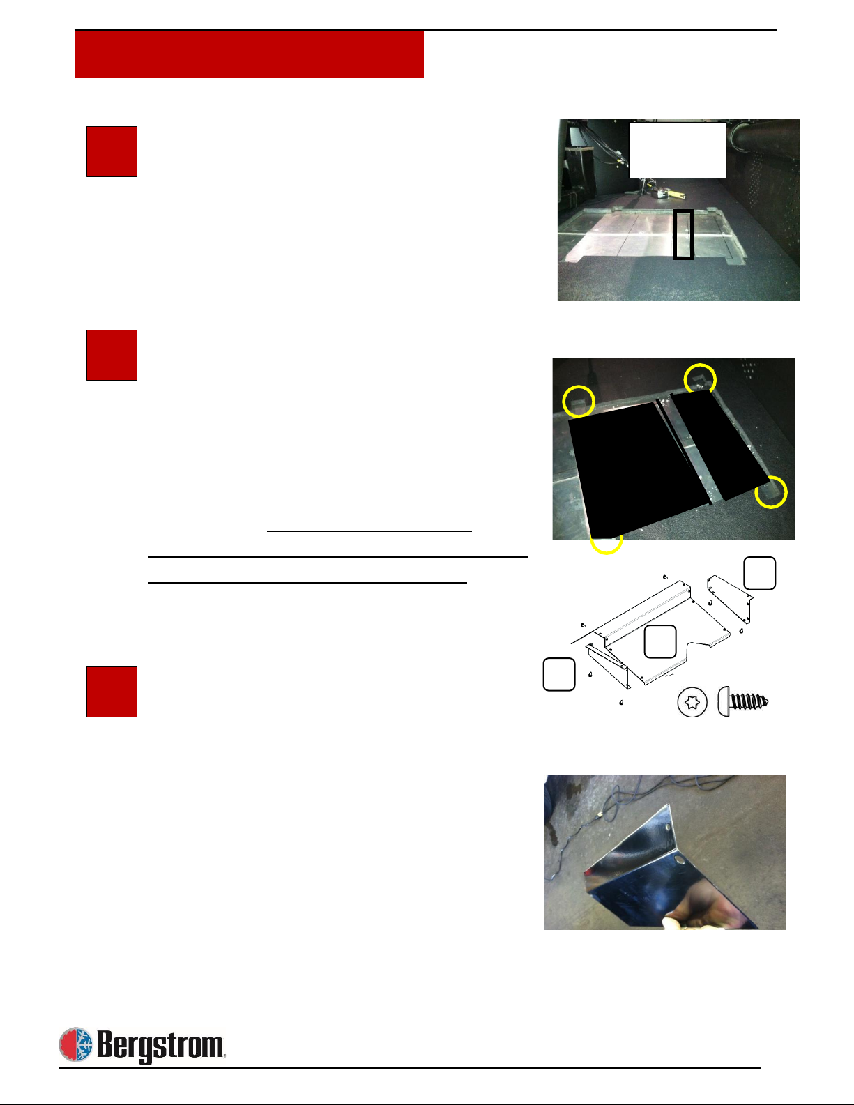
Floor Insulation
Determine approximate location for the
Phoenix unit. Measure 37 inches from the
driver side sleeper door and 4 ½ inches
from the rear wall liner. This will position the
Phoenix unit so the area between the 2
condenser openings will be centered above
the floor cross member. Remove the floor
insulation as shown, exposing the floor of
the sleeper.
Mark Area in Truck Floor to be Cut
Bend or remove the end tabs of the
template and position the template as
shown (see photo). Check under the truck
for any obstructions. Do not cut through
cross members. Mark the rectangular
openings in the template. Openings should
be large enough for the condenser air
bracket to fit inside (see photo step 5). Use
caution not to cut too large. Cross member
flange will be wider than the template
marks! Cut openings to edge of cross
member only.
DO NOT CUT CROSS MEMBER!
(See photo)
1
2
3
13
1-11
Installation Procedures
A
B
A
Do not cut
this area
Cut Hole in Truck Floor
Drill starter holes in all four corners of the
area marked for cutting. Note location of
cross members prior to drilling holes. Use
air saw/jigsaw to cut through truck floor.
Position the NITE Phoenix mounting
template, as shown, with the condenser
openings over the holes cut in the truck
floor. Mark 4 mounting feet locations as
indicated in photo. The unit has 8 possible
locations but you will only use 4. Use equal
spacing to provide adequate stability of the
Phoenix unit. Predrilling holes for the
mounting screws will aid in keeping the unit
square with the condenser openings.
Modify Condenser Air Inlet
Sides A will not be used. Cut section B as
shown in the next 2 photos. You will
remove the side that has the notch leaving
the top flat section on the piece to install.
4
5
6
14
1-12
Installation Procedures
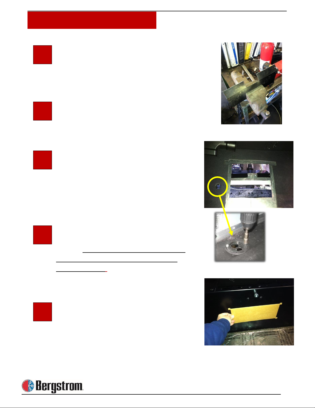
Modify Condenser Air Inlet
Measure and notch the flat mounting side of
the deflector so it will sit flat on the truck
floor avoiding the floor seam and rivets.
(See Photo)
Install the Condenser Air Inlet
Place modified deflector in the condenser
opening. Fasten with 1″ x 5/16 head self-
drilling screws.
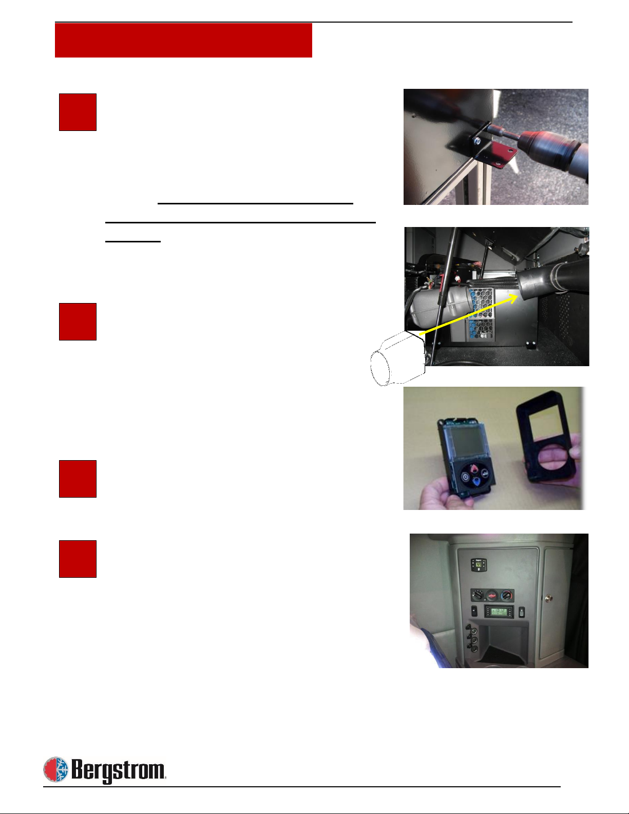
Cut Hole for Wiring Grommet
Using a 2″ hole saw, drill a hole for the
wiring grommet. We chose the location next
to the Phoenix where the wiring will drop
through the floor inside the frame rail.
Choose the best location for routing the
cables away from heat and sharp edges.
Install Wiring Grommet
Fasten with 1″ x 5/16 head self-drilling
screws. After wiring is complete, seal all
voids around wires and grommet with
silicone sealant.
NOTE: Silicone sealant not included in
installation kit
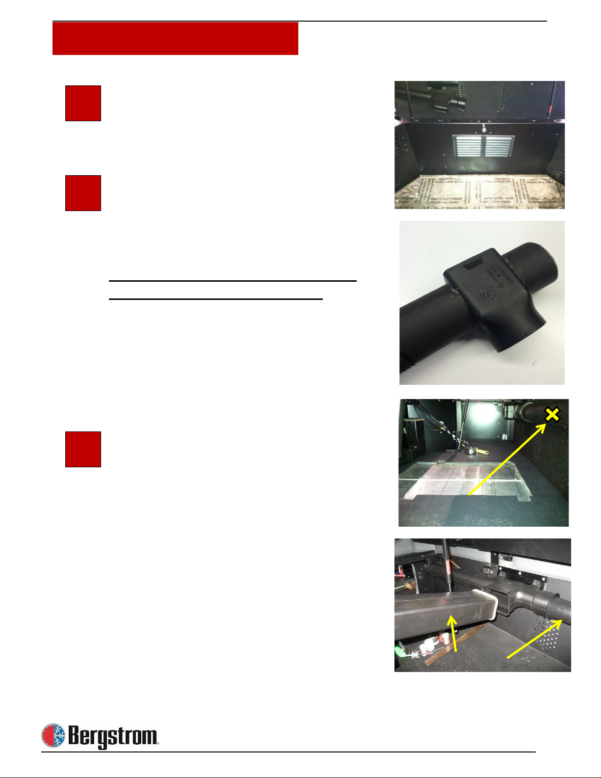
Cut Opening for the Recirculation Grill
Using provided template, locate center of
bunk support and mark area to be cut. Cut
and remove marked area. Also if
applicable, mark a location for the 2 ½ inch
round hole for the optional heater duct.
7
8
9
10
11
15
1-13
Installation Procedures
Install Recirculation Air Grill
Using black Phillips head screws provided.
New Duct Adapter Connect the Phoenix
Duct to the OE
Photo to the right shows duct adapter
already cut and ready for installation.
Before removing cross car duct, mark
the location for the duct adapter.
Line up the side of the adapter with the side
of the floor cut out and mark center of
adapter location.
Remove Both OE Duct Sections as
Indicated
12
13
14

16
1-14
Installation Procedures
Cutting the New Duct Adapter
Using the appropriate size hole saw, cut out
each side of the new duct adapter.
Slide Adapter Onto OE Duct
Center it on the X mark made in step 14.
Cut OE Duct Section as shown
Using an air saw, remove the marked
section. Use caution, do not cut too much.
The opening must be inside the adapter
when reinstalled.
Slide the Adapter Onto the OE Duct
Center adapter over the opening. Fasten in
place with self-drilling screws. Seal around
the adapter with silicone.
Reinstall Duct Assembly after Steps 35-
38 –Gravity Door Install
15
17
16
18
19

17
1-15
Installation Procedures
Prepare to Install Unit
Attach Seal Strip to Duct Bracket and
Elbow
Install foam seal around opening of flange
bracket and elbow.
Install the Duct Elbow Mounting Bracket
to the Phoenix unit using #10 X 1/2″ T20
elbow bracket screws.
Now Install One Half of the Elbow
Support Ring
Using elbow flange screws #8 X 3/4″ T20.
Do not completely tighten screws at this
time.
Slide the Elbow Into the Support Ring
facing what will be the back of thetruck and
install the second half.
Once Installed Snug All Screws
20
21
22
23
24
18
1-16
Install Mounting Feet
The Phoenix unit has 8 pre-dimpled
locations. Fasten feet in the 4 locations
matching the predrilled holes from page 13
step 5. Use 1″ x 5/16 hex head self- drilling
screws. Do not install feet where the
case is not dimpled or you will damage
the unit.
Install Phoenix Unit
Now secure the unit using eight 1″ x 5/16
head self-drilling screws.
New adapter replaces the install kit elbow
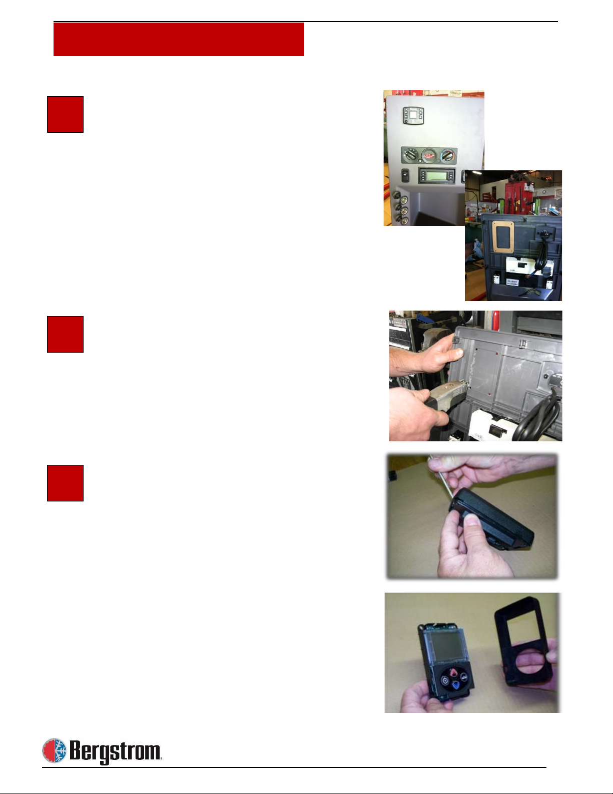
Prepare to Install the Phoenix Controller
Remove the OE Control Panel
Installation Procedures
25
26
27
28
19
1-17
Installation Procedures
Controller Location
On this model, the location for the controller
is stamped in the back of the OE panel.
Place the controller template in the area to
be cut to make sure the dimensions and
area are ok to cut.
Drill Starter Holes for Air Saw
Cut out marked section.
Attach Control Panel to the Sleeper
Carefully depress the lock and remove the
controller cover.
29
30
31

20
1-18
Installation Procedures
Install the Controller to the Control
Center
Using #10 x ½” T 20 torque head screw
(PN 600129). Do not over tighten.
Install Phoenix Control Harness
Route the controller harness from Phoenix
unit to control center area. Connect harness
to controller.
Install the OE Control Center
Gravity door: The purpose of this door is to
prevent the Phoenix system cool air from
flowing backwards through the OE bunk
unit.
Install the Provided Gravity Door
Modify OE duct.
32
33
34
35
Table of contents
Other Bergstrom Temperature Controllers manuals


