LSP inc. LSC1576 User manual

page 1
Manufacturers of Lakeshore Products
855 East Chicago Road, Quincy, MI 49082
www.lakeshoreproducts.com • tel: 517.639.3815 • fax: 517.639.4576
Owner’s Manual
LSC1576
1500 lb, 76" Beam Jet Lift
READ CAREFULLY - FAILURE TO FOLLOW INSTRUCTIONS AND SAFETY RULES MAY RESULT IN SERIOUS INJURY

LSC1576 Owner's Manual
page 2
spreaders 2
diagonal braces 2
bolt package step 2 1
1. mainframe setup
2. lower spreaders and diagonals
3. install H-units
mainframes [left and right] 2
w/ legs attached
H-units 2
bolt package step 3 1
Bolt the lower spreaders between the mainframes using:
8 – 5/16" x 2-1/2" hex bolts
8 – 5/16" at washers
8 – 5/16" nylon lock nuts
Install the diagonal braces from the front mainframe spreader to the
mainframe braces using:
4 – 5/16" x 2-1/2" hex bolts
4 – 5/16" at washers
4 – 5/16" nylon lock nut
Place the 2 H-units inside the mainframes and attach using:
4 – 1/2" x 4-1/2" hex bolts
12 – 1/2" at washers
4 – 1/2" nylon lock nuts
Place a washer under the head of each bolt, under the nut, and between
the H-unit and the mainframe. The bolts must be loose enough to allow
the H-units to pivot.
adjustable wrenches 2
or
1/2 wrenches 2
9/16 wrenches 2
3/4 wrenches 2
7/16 wrench [for winch] 1
tools needed
Setup the mainframes.
NOTE
Do not overtighten the nuts and bolts on your lift.
Doingsomaycause thelift tofail.Whentighteningagainst a tube,tighten
until the aluminum just dimples. If you crush the tube, it may crack and
fail under normal use.
LSC1576 1500 lb, 76" Beam Jet Lift
With proper care and maintenance, this lift will provide you with years of trouble free service. Please follow these instructions carefully.

LSC1576 Owner's Manual page 3
5. install winch
6. install wheel
4. side tubes and upper spreaders
Install the side tubes and the pulley bar between the top of the front and
rear H-units using:
4 – 1/2" x 5" hex bolts
8 – 1/2" at washers
4 – 1/2" nylon lock nuts
Be sure the long end of the side tube faces forward.
Install the upper spreaders between the side tubes using:
8 – 5/16" x 2-1/2" hex bolts
8 – 5/16" at washers
8 – 5/16" nylon lock nuts
Install the winch on the desired side of the lift using:
2 – 3/8" x 5-1/2" hex bolts
4 – 3/8" at washers
2 – 3/8" nylon lock nut
CAREFULLY thread the 25" red wheel onto the winch shaft. The wheel
should be able to thread on and o the shaft easily. This is the action that acti-
vates the brake mechanism.
Turn the wheel clockwise and you should here a clicking sound, this
means the brake is working. This raises the lift and keeps it raised
wherever you stop. Turn the wheel counter clockwise and the brake is released
allowing the lift to lower.
To keep the wheel from coming o the shaft fasten using:
1 – winch spring
1 – 1/2" jam lock nut
Tighten the nut just until 1 or 2 threads of the shaft are visible while preventing
the winch shaft from turning.
winch 1500# 1
red wheel 25" 1
bolt package step 5 1
side tubes 2
spreaders 2
bolt package step 4 1
pulley bar 1
NOTE
The wheel needs to thread on and o
the shaft to activate the brake. This
shaft should be greased yearly to
ensure proper operation.
Extreme care should be taken not to
cross thread and damage the threads
on the wheel hub. This will void your
warranty.

LSC1576 Owner's Manual
page 4
cable 3/16" x 252" 1
bolt package step 7 1
9. nal adjustments
8. bunks
7. string cable
vinyl wrapped aluminum bunks 2
bunk adjustment channels 4
bunk backer plates 4
bolt package step 8 1
plastisol cap 1 1/2" x 4 1/2" 2
plastisol cap 1 1/2" x 2" 4
Attach the loop end of the cable to the mainframe opposite the winch
using:
1 – 3/8" x 5-1/2" hex bolt
2 – 3/8" at washers
1 – 1/2" at washer
1 – 3/8" nylon lock nut
String the cable through the pulley bar and secure it to the winch following
the instructions included with the winch.
Attach the vinyl wrapped aluminum bunks to the front and rear cradles
using:
4 – 5/16" x 1" hex bolts
8 – 5/16" x 2-1/2" hex bolts
12 – 5/16" lock nuts
For most uses bunks should be placed approximately 18" apart. Make sure
the bunk adjustment channels are on the outside of the lift as shown.
Now tighten all nuts and bolts, except the ones from Step 3 and 4 that must
be free to allow the H-units to pivot.
Install the 6 plastisol caps, 2 at the top of the mainframe and 4 on the
legs.
Move your lift into the water and adjust the legs so that the lift is level.
The legs can be removed to lower the lift if the water is very shallow.
Adjust the bunk height just high enough so your craft's bottom will not hit
the cradle.
The installation is now complete.
NOTE
Never over crank the winch. Once
the lift has reached its highest
point, further cranking will damage
the lift.

LSC1576 Owner's Manual page 5
important
A. Grease the winch shaft annually. The red wheel must be able to thread and unthread easily in order for the braking mecha-
nism to work properly.
B. Your LSP Lift will only protect your boat if it is lifted well above the level of the water. In larger lakes or during storms, large
waves may lift the craft from the lift or tip the lift over, causing damage both to the boat and the lift. You must take precau-
tions to protect your craft and lift from these conditions. If your craft suers damage from high waves, LSP, Inc. will not accept
responsibility for such damage.
C. Inspect your lift often for signs of wear or improper operation. Be aware of normal cranking force. Any increase in cranking
force is a sign that something is wrong. DO NOT USE the lift if any parts are worn or damaged, replace immediately.
D. Pay attention to the condition of your cable. A frayed or rusted cable can lead to failure of the lift. Replace it immediately.
Greasing the cable, especially where it enters the winch, can extend its life.
E. A second caution decal is provided in the accessories box. If after assembly the decal is not easily seen then install the extra
decal so that anyone using the lift can read it. NEVER let anyone operate the lift unless they are familiar with all safety rules.
F. NEVER let anyone play on, around, or under the lift.
hints
A. Place your lift in the deepest water you can, your lift will operate most easily at the top of its lifting range.
B. Deep V hulls may be accomodated by moving the front of the bunks closer together and leaving the back farther apart to
provide stability.
C. In deep water ? If you have a deep lake and are in need of longer legs, LSP, Inc. oers 4 foot long legs for your PWC Lift. Ask
your dealer for details or call us at 517.639.3815.
D. Greasing the cable where it wraps around the winch drum will increase cable life.
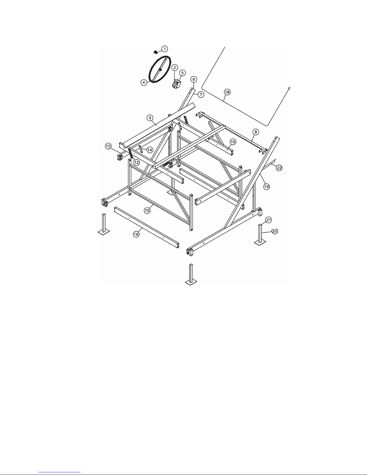
bolt package with steps 1-8 1
bunk adjustment channels 4
bunk backer plates 4
2500# DL winch and booklet 1
cable with loop in one end 1
1 1/2" x 4 1/2" caps 2
1 1/2" x 2" caps 4
accessory package 1576
Ten/Two Year Limited Warranty
LSP, Inc. (Seller) warrants the aluminum structure on docks and lifts of its manufacture to be free from defects caused by material or
workmanship for ten years from date of purchase. Seller will, at its option, repair or replace any such goods found on examination by Seller to
be defective under normal use and service. Upon discovery of any such defect, Buyer must notify Seller in writing of defect and provide proof of
purchase. Seller warrants all other materials including cast aluminum parts, mechanical components, hardware, canopy covers, cables, bunks,
etc for two years. Components obtained from other manufacturers and used in Seller’s products will be covered under the manufacturer’s
warranty and shall not be the responsibility of the Seller.
Seller’s responsibility under this warranty shall be the repair or replacement of defective items. Seller is not liable for incidental or consequential
damages of any kind.
Seller shall not be held responsible for repairs or modications to its docks or lifts unless authorization has been obtained from Seller. This
warranty does not cover damage caused by incorrect assembly or adjustments, overloading, improper use, neglected maintenance, alterations,
or damage caused by accident, environmental factors (chemicals, tree sap, salt, etc), or acts of God (rainstorms, windstorms, tornadoes, etc).

page 6
LS0249/102218
LSC1576 1500 lb, 76" Beam, 35" Lift Height.
PARTS LIST
ref. part no. part name qty.
1 20552 Wheel Knob 1
2 20498 Winch Hardware 1
4 LS1102 25" JL Wheel 1
5 20933D Dutton-Lainson
DLB-2500 Winch 1
6 CAPS1545 1 1/2" x 4 1/2" Cap 2
7 20924 Left Mainframe 1
8 20930 Pulley Bar Assembly 1
9 21021 Vinyl Wrapped
Aluminum Bunk 2
10 20928 Side Tube 2
12 20501 Bunk Adjustment
Channel 4
14 20502 Bunk Backer Plate 4
15 20926 H Unit 2
16 20927 Spreader 4
18 20464 Cable 3/16" x 252" 1
19 20925 Right Mainframe 1
20 JLU Leg 4
21 CAPS1520 1 1/2" x 2" Cap 4
22 20929 Diagonal Brace 2
LSC1576 BOLT PACKAGE
part no. part name qty.
20937 STEP 2
X310 5/16" x 2-1/2" Hex Bolt 12
Z351 5/16" Nylon Lock Nut 12
X352 5/16" Flat Washer 3/4" OD 12
20634 STEP 3
X518 1/2" x 4-1/2" Hex Bolt 4
X552 1/2" Flat Washer 12
Z551 1/2" Nylon Lock Nut 4
20938 STEP 4 1
X310 5/16" x 2-1/2" Hex Bolt 8
Z351 5/16" Nylon Lock Nut 8
X352 5/16" Flat Washer 8
X520 1/2" x 5" Hex Bolt 4
Z551 1/2" Nylon Lock Nut 4
X552 1/2" Flat Washer 8
part no. part name qty.
20939 STEP 5
X422 3/8" x 5-1/2" Hex Bolt 2
Z451 3/8" Nylon Lock Nut 2
X452 3/8" Flat Washer 4
20498 Winch Hardware 1
20940 STEP 7
X422 3/8" x 5-1/2" HEX BOLT 1
Z451 3/8" Nylon Lock Nut 1
X452 3/8" Flat Washer 2
X552 1/2" Flat Washer 1
20637 STEP 8
X304 5/16" x 1" Hex Bolt 4
X310 5/16" x 2-1/2" Hex Bolt 8
Z351 5/16" Nylon Lock Nut 12
Table of contents
Other LSP inc. Lifting System manuals
Popular Lifting System manuals by other brands

WilTec
WilTec 30182 Operation manual

probst
probst SH-1000-MINI operating instructions

AGM
AGM G50 Series INSTALLATION, USE, MAINTENANCE AND SPARE PARTS

Bishamon
Bishamon BSC3200 Series Operation and service manual

Ravaglioli
Ravaglioli RAV835.10I Original instructions

Vestil
Vestil S-FORK-4/6-RL owner's manual

AussieCarHoists
AussieCarHoists YL-240 Installation and operation manual

MSW Motor Technics
MSW Motor Technics MSW-MD-800 user manual

Peak
Peak Amgo 414A Installation and service manual

Terex
Terex Genie SHOV5DL15B-1001 Operator's manual

BorMann
BorMann PRO BWR5516 manual

The Handy
The Handy 21660 instructions