Piktogramme/
Pictograms
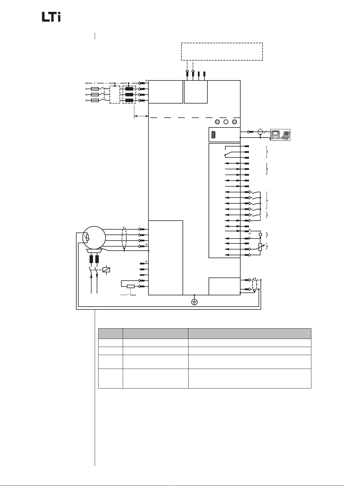
Ausführungsbeschreibung CDA/CDD54.xxx
CDA/CDD54.xxx Specification
ID no.: 1001.21B.2-00 • 04/2014
Technische Änderungen vorbehalten.
Subject to technical changes.
Achtung! Fehlbedienung kann zu
Beschädigung oder Fehlfunktion des
Antriebs führen.
Attention! Misoperation may result in
damage to the drive or malfunction.
Gefahr durch elektrische Spannung!
Falsches Verhalten kann Menschenle-
ben gefährden.
Danger from electrical tension! Impro-
per behaviour may endanger human life.
Gefahr durch rotierende Teile! Antrieb
kann automatisch loslaufen. Danger from rotating parts! The drive
may start running automatically.
Hinweis: Nützliche Information Note: Useful information
Verweis auf andere Dokumente Reference to other documents
Hinweis: Diese Ausführungsbeschreibung
ist keine Betriebsanleitung!
Sie ergänzt die Betriebsanleitun-
gen der jeweiligen Baureihen um
die Beschreibung der Bauvarian-
ten.
Note: This specification manual is not an
operation manual!
It is an add on to the referring ope-
ration manual of the units.
Grundsätzlich muss jede Person, die mit der
Montage, Inbetriebnahme, Bedienung und
Instandhaltung (Inspektion, Wartung, Instand-
setzung) des Umrichters befasst ist, eine ent-
sprechende autorisierte, eingewiesene und
qualifizierte Elektrofachkraft im Sinne VDE
0105 sein.
Any person involved with the installation, com-
missioning, operation and maintenance
(inspection, maintenance, and repair) of the
inverter must be an authorised, trained and
qualified electrician in accordance with VDE
0105.
Diese Elektrofachkraft muss diese Ausfüh-
rungsbeschreibung und die Betriebsanleitung,
im besonderen die Sicherheitshinweise, gele-
sen und verstanden haben.
The qualified electrician must have read and
understood this specification, the operation
manual and in particular the safety information.
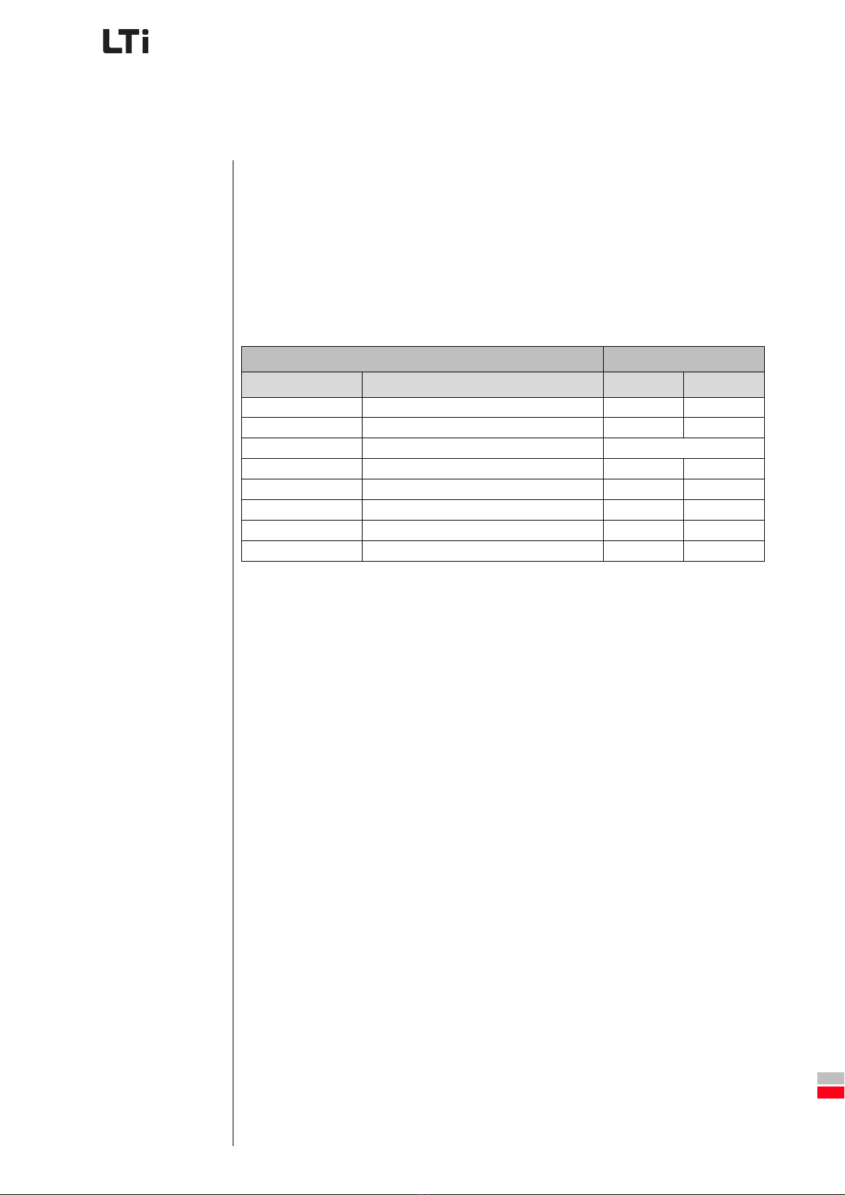
Geräte mit folgender Bezeichnung werden in dieser
Ausführungsbeschreibung beschrieben: Devices with the following nominations are described in
this specification:
➢ CDA54.xxx
➢ CDD54.xxx
➢ CDA54.xxx
➢ CDD54.xxx
D