1-2
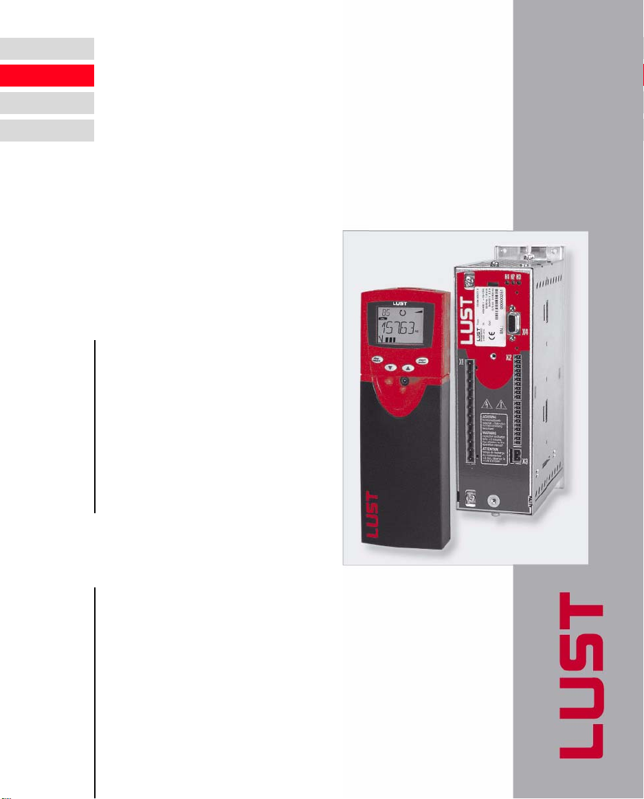
CDA3000 Operation Manual
1 Safety
1.2 Intended use Inverter drives are components that are intended for installation in
electrical systems or machines. The drive may not be commissioned
(i.e. it may not be put to its intended use) until it has been established that
the machine as a unit complies with the provisions of the Machinery
Directive (98/37/EC). EN 60204 (Safety of machines) is to be observed.
Warning: This is a product with restricted availability in accordance with
IEC 61800-3. The Inverter Drive System may cause radio frequency
interference in residential environments. In such cases operators may
need to implement appropriate countermeasures.
If the frequency inverter is used for special applications (e.g. in areas
subject to explosion hazard), the required standards and regulations
(e.g. EN 50014, “General provisions” and EN 50018 “Flameproof
housing”) must always be observed.
Repairs may only be carried out by authorized repair workshops.
Unauthorized opening and incorrect intervention could lead to physical
injury or material damage. The warranty provided by LUST would thereby
be rendered void.
1.3 Responsibility Electronic devices are fundamentally not fail-safe. The company setting
up and/or operating the machine or plant is itself responsible for ensuring
that the drive is rendered safe if the device fails.
EN 60204-1/DIN VDE 0113 “Safety of machines”, in the section on
“Electrical equipment of machines”, stipulates safety requirements for
electrical controls. They are intended to protect personnel and machinery,
and to maintain the function capability of the machine or plant concerned,
and must be observed.
The function of an emergency off system does not necessarily have to cut
the power supply to the drive. To protect against danger, it may be more
beneficial to maintain individual drives in operation or to initiate specific
safety sequences. Execution of the emergency off measure is assessed
by means of a risk analysis of the machine or plant, including the
electrical equipment to DIN EN 1050, and is determined with selection of
the circuit category in accordance with DIN EN 954-1 “Safety of machines
- Safety-related parts of controls”.
The CDA3000 conforms to the Low Voltage Directive
DIN EN 50178.
EMC Application of the installation instructions ensures
conformance to product standard EN 61800-3. It covers:
• Public low voltage system:
Residential areas up to 10 metres motor cable length
• Industrial low voltage system:
Industrial areas up to 25 metres motor cable length