Lubing EasyLine Operation and maintenance manual

0940-1_M+B-PutentraenkeGB
Watering Systems
Assembly Instructions
and
Operators manual
Turkey drinking system“EasyLine”
Issued: January 2008

0940-1_M+B-PutentraenkeGB LUBING Floor Watering System
- 2 -
Manufacturer data
Manufacturer / Service information
Manufacturer:
LUBING Maschinenfabrik GmbH & Co. KG
Am Kampe 60
49406 Barnstorf / GERMANY
Tel.: +49 (0) 5442 / 9879 - 0
Fax: +49 (0) 5442 / 9879 - 33
e-mail: [email protected]
Internet: www.lubing.de
Service:
Dealer stamp
Document data
Assembly and Operating Instructions file name: 0940-1_M+B-PutentraenkeGB.doc
Version: 2.2
Firstissued: 07.10.2003
Last modified: 24.01.2008
See last page for overview of modifications
Dear Reader,
Permanent development of our products and innovative new designs mean that our assembly and
operating instructions as well as spare parts sheets are regularly updated. If you have any queries,
please contact us or your LUBING dealer.
Current status online at: www.lubing.de
©2003 LUBING Maschinenfabrik GmbH & Co. KG, Am Kampe 60, 49406 Barnstorf.
All rights reserved. Reprints, incl. excerpts thereof, only with authorisation of the company

0940-1_M+B-PutentraenkeGB LUBING Floor Watering System
- 3 -
Contents
Manufacturer data ................................................................................................................................... 2
1. Introduction.......................................................................................................................................... 4
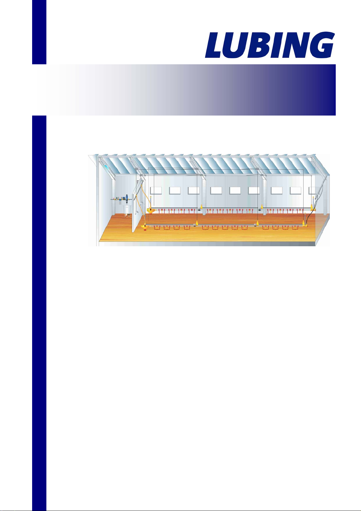
1.1 Brief description of LUBING watering systems for floor watering.................................................. 4
1.2 Designated use.............................................................................................................................. 4
2. General information............................................................................................................................. 5
2.1 Warnings and symbols .................................................................................................................. 5
2.2 General safety guidelines.............................................................................................................. 6
2.3 Obligations and liability.................................................................................................................. 6
2.4 Warranty and liability:..................................................................................................................... 7
2.5 Electrical system............................................................................................................................ 7
3. Assembly............................................................................................................................................. 8
3.1 Assembly information..................................................................................................................... 8
3.2 Assembly order.............................................................................................................................. 8
3.3 Spare parts .................................................................................................................................... 8
3.4 Assembly overview........................................................................................................................ 9
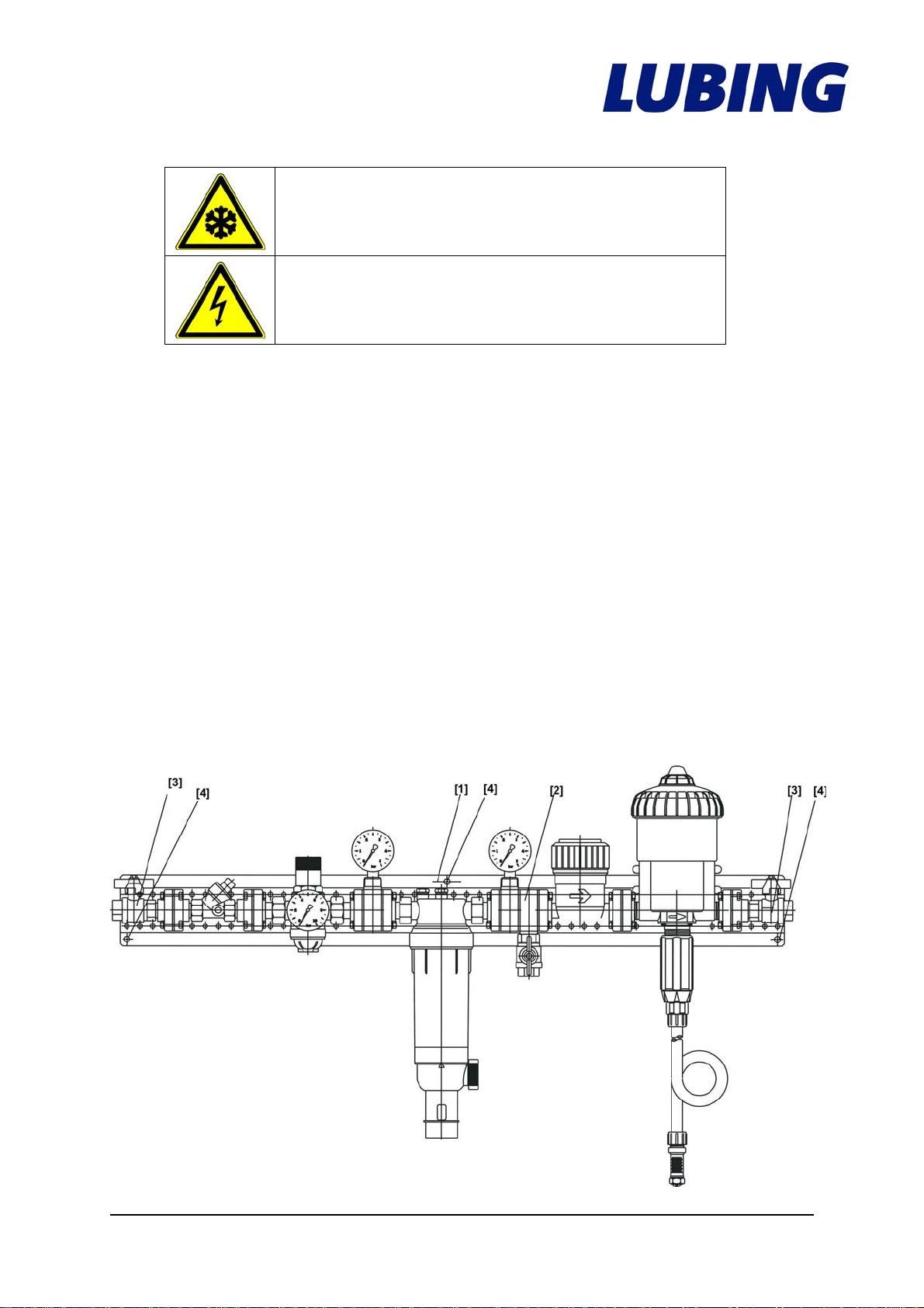
3.5 Fitting the Main Water Supply...................................................................................................... 10
3.6 Mixer ............................................................................................................................................ 12
3.7 Connection accessories............................................................................................................... 12
3.8 Glued connections....................................................................................................................... 14
3.9 Fitting the drinking line................................................................................................................. 16
3.9.1 Mounting the Hand Winches.................................................................................................17
3.9.2 Mounting the Ceiling Winches............................................................................................... 18
3.10 Pressure Regulator.................................................................................................................... 20
3.12 Breather Unit.............................................................................................................................. 21
4. Operating Instructions ....................................................................................................................... 25
4.1 Adjusting the turkey drinker ......................................................................................................... 26
4.2 Before hutching............................................................................................................................ 28
4.3 Cleaning of the drinking line ........................................................................................................ 28
4.3.1 Cleaning the nipple drinking system of dirt and lime accumulation...................................... 28
4.3.2 Cleaning the nipple drinking system of algaes and accumulations of medicaments............ 30
4.3.3 Cleaning of the dosing system.............................................................................................. 33
4.3.4 Cleaning of the water filter .................................................................................................... 33
4.4 Vaccinating via drinking water..................................................................................................... 35
4.5 Hutching in................................................................................................................................... 36
4.6 While rearing................................................................................................................................ 36
4.7 While fattening............................................................................................................................. 36
4.8 Between the circles...................................................................................................................... 36
4.9 Height table.................................................................................................................................. 37
4.10 Timer for magnetic valve ........................................................................................................... 38
4.11 Attendance and maintenance, fault clearance .......................................................................... 39
Cup is empty.......................................................................................................................................... 39
5. Modification notes.............................................................................................................................. 40

0940-1_M+B-PutentraenkeGB LUBING Floor Watering System
- 4 -
1. Introduction
1.1 Brief description of LUBING watering systems for floor watering
LUBING nipple watering systems for turkeys* supply the animals with drinking water.
This requires the availability of sufficient quantities of fresh and clean drinking water
which must be free of contamination and easily accessible.
LUBING nipple watering systems comprise the following components:
•Pressure Regulator unit
•Nipple pipe with nipples and cups
•Breather unit
Drinking accessories with:
•Main Water Supply
•Medicator
•Mounting Accessories
1.2 Designated use
LUBING nipple watering systems are exclusively intended for standard applications
in supplying Turkeys* with drinking water.
The maximum slope from the Pressure Regulator to the Breather Unit may not
exceed 1.5% (1.5 metres difference in height along a house length of 100 metres).
Systems with oval cups are designed for breeding to approx. the 6th week and
for fattening hens until ready for sale. Systems with round cups are designed
for fattening male birds from approx. the 6th week until ready for sale.
Any other use shall not be regarded as proper. The manufacturer will not be liable for
any ensuing damage; this risk shall be borne by the user alone.
Designated use also includes:
•observing all of the information in the Operating Instructions and
•carrying out all service and maintenance work as required.
LUBING nipple watering systems may only be operated, maintained and serviced by
personnel familiar with these measures and the potential dangers associated with the
system.
Turkeys*: Depending on the design or system – to approx. the 6th week for turkey breeding, from the
6th week until ready for sale in the case of fattening male and female birds.

0940-1_M+B-PutentraenkeGB LUBING Floor Watering System
- 5 -
2. General information
2.1 Warnings and symbols
You will come across the following symbols while reading this manual.
Warns of general danger
Warns of dangerous electrical current
Warns of cold
Warns of corrosive substances
Warns of flammable substances
Substances detrimental to health
General mandatory sign
Mandatory sign indicating protective gloves

0940-1_M+B-PutentraenkeGB LUBING Floor Watering System
- 6 -
2.2 General safety guidelines
The relevant guidelines for the prevention of accidents as well as other generally
recognised technical safety and medical regulations for the workplace must be
observed. Check that the safety and functional equipment works safely and correctly:
•prior start-up
•at the appropriate intervals
•following modifications or maintenance.
The specifications outlined by the water and energy utility companies must also be
observed.
These Operating Instructions include the most important information for operating the
drinking systems in a safe manner.
2.3 Obligations and liability
Observe information in the Operating Instructions
A basic prerequisite for safe handling and smooth operation of this watering system
is knowledge of the basic safety information and safety guidelines. These Operating
Instructions, and the safety instructions in particular, must be observed by all persons
working on the watering system. Furthermore, all regulations and guidelines
governing the prevention of accidents and applicable for the respective site must also
be observed.
The watering system may only be used as designated when it is in a safe technical
state. Any problems which may impair safety must be remedied without delay.
Organisational measures:
All safety equipment must be examined at regular intervals.

0940-1_M+B-PutentraenkeGB LUBING Floor Watering System
- 7 -
2.4 Warranty and liability:
As a general rule, our “General Terms and Conditions Governing Sale and Supply”
shall apply.
Warranty and liability claims in the event of personal and material damage are
excluded if they are attributable to one or more of the following causes:
•non-designated use of the watering system,
•improper fitting, commissioning, operation and service of the machine,
•operation of the machine despite defective safety equipment or safety and
protective equipment which has been fitted incorrectly or is non-functional,
•non-observance of the information in the Operating Instructions as regards
transport, storage, fitting, commissioning, operation, service and equipment
of the system,
•independent structural modifications to the system,
•poor supervision of components subject to wear,
•repairs carried out incorrectly,
•catastrophes caused by foreign bodies and forces majeures.
2.5 Electrical system
A
lways isolate the power supply before working on
the electrical system.
All tasks extending beyond the framework of system maintenance may only be
carried out by qualified personnel.
Always isolate the power supply when working on the device and secure against
unauthorised reactivation by another person.
Examine electrical cables for visible damage prior to commissioning.
Replace any damaged lines before putting the device into operation.
Damaged or destroyed plug devices must be replaced by a qualified electrician.
Do not remove plugs from sockets by pulling the cable.
Covering electrical components can give rise to heat concentration with high
temperatures which can in turn destroy the equipment and cause fires.

0940-1_M+B-PutentraenkeGB LUBING Floor Watering System
- 8 -
3. Assembly
3.1 Assembly information
Please read the following pages carefully. The instructions in this manual apply for
various drinking systems. For this reason, we would ask you to select and apply the
sections which concern you.
When using this manual for LUBING standard versions, please note all alterations to
and/or deviations from the scope of your supply.
3.2 Assembly order
Use the Table of Contents to find the assembly section you require.
The assembly section describes the individual work steps in the assembly order.
Individual components are provided with position numbers in the drawings. These
position numbers can also be found in the text.
3.3 Spare parts
Spare parts for the nipple drinking system you will find in the "Spare parts list for floor
watering systems" article no. 9903.
This contains the exact name of the respective part and its item number, which we
require in the event of spare parts being ordered.
In order to procure electrical components, we require information on the power
supply, e.g. 230/400 V – 3 Ph. 50 Hz.
A current version is appended to these Assembly and Operating Instructions.

0940-1_M+B-PutentraenkeGB LUBING Floor Watering System
- 9 -
3.4 Assembly overview
Principal design of LUBING nipple watering systems:
1 Water supply
2 Pressure Regulator with flush system
3 Nipple pipe with nipple, pendulum and cup
4 Couplings
5 Suspension
6 Breather units
1 2 3 4 5 6

0940-1_M+B-PutentraenkeGB LUBING Floor Watering System
- 10 -
3.5 Fitting the Main Water Supply
Overview on page 10, section 1
Protect from frost.
Frost can destroy the components!
For versions with solenoid valve:
Fit switching cabinet in such a way that it is protected
from water!
The Main Water Supply should be attached in such a way that it is always protected
from frost.
For versions with a solenoid valve, the standard version of the time relais must be
connected to a mains voltage of 240 V 50 Hz via the mains plug.
Please note the information on mains voltage on the delivery note.
The components required for the Main Water Supply are supplied ready-assembled.
The attachment (a stable metal console [1]) guarantees a firm, secure and
waterproof connection of the components. The Main Water Supply can therefore be
installed on the wall, usually in the front part of the building. The 6 drill holes [4] in the
metal console are 10 mm in diameter.
The flange connections [2] permit easy exchange of individual components. The
connections to the Main Water Supply are provide d by the ¾" internal screw threads
of the Ball Valves (inlet and outlet [3]).
4265-3

0940-1_M+B-PutentraenkeGB LUBING Floor Watering System
- 11 -
The Main Water Supply is secured horizontally to the point specified in the plans.
Please observe the flow direction (arrow on theWater Meter) when connecting to the
water supply!
For versions with Medicators:
Observe overall height of Mixers!
Please ensure that there is sufficient space under the Main Water Supply for the
Mixer, item no. 4248, for 60 litres (height: 73 cm) or Mixer, item no. 4258, for 180
litres (height: 97 cm) or another container for medication solutions.
For versions with reversible flow filter:
The backwash water must be directed towards the
waste water channel in such a way that the
possibility of backpressure is eliminated!
There are 3 ways of fitting the reversible flow filter:
1. Direct connection:
Transition Piece DN 50/70 with required
pipes and trap
(three 90° bends) in DN 70
2. Draining off freely into floor outlet
3. Draining off into open
Filter size Backwash volume*
½“ and ¾“ 12 litres
1“ and 1 ¼“ 15 litres
1 ½“ and 2“ 18 litres
* at 3 bar supply pressure and backwash duration
of 15 seconds
The connection to a public supply line is made in
accordance with the specifications of the responsible
water utility company!

0940-1_M+B-PutentraenkeGB LUBING Floor Watering System
- 12 -
3.6 Mixer
Overview on page 10, section 1
The LUBING Mixer must stand on a level and even surface.
The water supply connection is achieved via ¾“ Gardena Seals. When using a Main
Water Supply, a ¾“ hose can be laid from the Ball Valve in front of the Water Meter.
This requires a Hose Connector.
The standard version must be connected to mains voltage of 240 V 60 Hz using a
mains plug.
Please observe the information on mains voltage supplied on the delivery note.
3.7 Connection accessories
Overview on page 10, section 1
LUBING offers a variety of accessories for the water connection. We recommend
using the LUBING range of plastic pipes for pipework into the housing unit. Apart
from ∅25 mm and ¾“ pipes, this range also includes Couplings, Bends ,T-pieces,
End Caps and Threaded Connection Pieces for both pipe diameters permitting all
kinds of pipework layouts. These components must be glued to ensure leak-proof
assembly.
Please refer to section 3.8 on Glued Connections.
The pipe system is secured to the wall or ceiling using Ceiling Clips, item no. 4349
for the 25 mm pipe and item no. 4329 for the ¾“ pipe. Mark the pipe layout and screw
down the Holders, item no. 4329 / 4349. Then press the pipes into the Holders.
Check the entire pipe system for leaks prior to commissioning.
LUBING recommends using the Water Connection Kit for connecting the drinking line
Pressure Regulator to the water supply. Depending on the kit, the following parts are
supplied:
Item no. Components
4150 Clamp Ø ¾", Hose Connector, 3 m Tube ½“ and
Clips
4151 Clamp Ø ¾", Hose Connector, 4 m Tube ½“ and
Clips
4152 Clamp Ø ¾", Hose Connector, 5 m Tube ½“ and
Clips
4153 Clamp Ø ¾", Hose Connector, 3 m Tube ½“, Ball
Valve and Clips
4154 Clamp Ø ¾", Hose Connector, 4 m Tube ½“, Ball
Valve and Clips
4155 Clamp Ø ¾", Hose Connector, 5 m Tube ½“, Ball
Valve and Clips

0940-1_M+B-PutentraenkeGB LUBING Floor Watering System
- 13 -
Fitting the Water Connection Kit
Overview on page 10, section 1
The Clamp must be secured to the ¾“ pipe.
Do this by drilling a hole 10 mm in
diameter (2) in the water pipe.
Ensure that there is no water in the
pipe before drilling!
Burr the drill hole!
Rinse out any chips from the pipe!
Do not commence assembly of the Clamp
until after rinsing first.
Securing the Clamp:
Insert the Clamp (3) and thorn in the drilled
hole on the pipe. Make sure the O-ring seal
is positioned correctly. Place the top part of
the Clamp (1) on the pipe and secure
using the two screws.
Secure one end (5) of the hose to the Hose
Connector (4) using the clip. Screw the Hose
Connector to the flat packing in the Clamp (3). Insert the
other end of the hose into the Pressure Regulator (6)
Hose Connector and secure with a clip.
This must be installed with flat packings in the case
of Ball Valve (7) versions (see versions on page 12).
If required, the Ball Valve can be mounted
between the Pressure Regulator and the
Hose Connector (see graphic on right) if you
wish to have the Ball Valve directly on the
drinking line.
Or you can mount it between the Hose Connector (4) and the Clamp (3) in
order to block the water supply directly at the supply point.

0940-1_M+B-PutentraenkeGB LUBING Floor Watering System
- 14 -
3.8 Glued connections
LUBING recommends "Tangit" adhesive, article no. 4405, for glued connections.
Many connection elements in the LUBING product range are designed as glued
connections. Please observe the following manufacturer instructions in order to
ensure secure connections.
The pipe must be cut at a right angle and burred. The areas to be glued must be
clean and dry. Clean the ends of the pipe on the outside and the connecting
elements on the inside using a cleaning agent (please check compatibility) and
woven felt. Always use new woven felt. The areas to be glued must be fully dry
before applying the adhesive.
Push the pipe and connecting element without twisting until the limit stop and hold
tight for a few seconds until the glue has set. Immediately following joining, remove
superfluous glue with the woven felt as otherwise the pipe will be etched too strongly.
Owing to the fast setting features of the adhesive, the join parts must be pushed
together within 4 minutes of applying the glue. The open period for Tangit depends
on the ambient temperature and/or film thickness.
Ambient temperatue Processing time Film
thickness
20 °C approx. 4 min. 1 mm
25 °C 3 min. 1 mm
30 °C 2 min. 1 mm
40 °C 1 min. 1 mm
> 40 °C < 1 min. 1 mm
Stress: Do not move the pipes for at least 5 minutes after gluing. At temperatures
below 10°C, this period is extended to a minimum of 15 minutes.
Pressure test: The pipes should not be filled nor should a pressure test be carried out
until 24 hours after the last gluing procedure. We recommend rinsing pipes and
possibly even leaving them full of water if they are not put into operation immediately.
Please observe the protective measures described by the manufacturer.
Please also observe additional information in the data sheets and guidelines on the
prevention of accidents supplied by the professional associations, e.g. VBG 15, VBG
81, M017 and the Safety Data Sheets.
Tangit contains tetrahydrofurane and cyclohexanone.
Xi = irritable
Irritates the eyes and breathing apparatus
“Tangit” adhesive is highly flammable.
F = easily flammable!

0940-1_M+B-PutentraenkeGB LUBING Floor Watering System
- 15 -
Tangit is highly inflammable. Its solvent vapours are heavier than air and can form
explosive mixtures. For this reason, always ensure sufficient ventilation when
processing, drying or gluing using Tangit. In workrooms and adjoining rooms: No
smoking! No welding! No naked flames and avoid generating sparks! Prior to welding
work, accumulations of solvent vapours and explosive mixtures must be removed. Fill
pipelines with water, rinse well and blow through. Do not seal pipes during the drying
phase.
Longer inhalation of these solvent vapours can lead to impaired health. Store used
woven felt in closed containers.
We recommend wearing protective gloves as a precaution for preventing contact with
the skin. If the substance comes into contact with the eyes, rinse thoroughly with
water and consult a doctor.
Safety advice:
•Must be kept out of reach of children.
•Keep away from ignition sources – no smoking.
•Avoid contact with eyes.
•If ingested, consult a doctor and show packaging or label.

0940-1_M+B-PutentraenkeGB LUBING Floor Watering System
- 16 -
3.9 Fitting the drinking line
Overview on page 10, section 2 - 6
LUBING drinking lines comprise pre-assembled elements 3 metres in length, the
Pressure Regulator and Breather Unit.
Suspension units, ropes with adjusting and retaining panels, ceiling pulleys and
hooks are used for suspending the drinking line.
The drinking line is adjusted in height via traction ropes, guide pulleys and
handwinches.
The handwinches are secured at the front in the case of short houses.
In the case of long houses (100 - 150 metres), ceiling winches are used in the centre
of the house.
If you have not installed a Main Water Supply as described in 3.5, please observe the
following:
A water filter must be fitted in any case!
The water supply line via the wall or ceiling should be at least ¾“ in diameter.
The individual supply line from the ceiling to the Pressure Regulators is laid as a ½“
pressure hose (fibrous).
If using a proportioning unit, we recommend the LUBING Mixer.
Please assemble as follows:
Overview on page 10, section 5
1. Measure the width of the house, specify the position of the drinking line and
sketch it on the front and back walls of the building. The number of drinking lines
per building is specified in the layout.
2. Calculate the length of the drinking line and determine the distance between it
and the front and back walls.
3. Specify and screw in the first (1) and last (5) ceiling
hook for each row
4. Secure a string between the two ceiling hooks (1) and (5).
5. Screw in all of the ceiling hooks (4) approx. 3 metres
apart and on alternating sides of the string. They
should be approx. 20 cm away from the string.
Position another ceiling hook 20 cm from the string
and opposite the second ceiling hook (2).

0940-1_M+B-PutentraenkeGB LUBING Floor Watering System
- 17 -
Go to 10 for suspension using Ceiling Winches.
3.9.1 Mounting the Hand Winches
6. Once the ceiling hooks have been inserted for each of the drinking lines, the
traction rope is suspended. The traction rope is placed through the open eyelet of
the ceiling hooks for each drinking line and secured to the end (ventilation side) of
the last ceiling hook.
Caution! In order to prevent the traction rope from
twisting, it must be unwound. Kinks and knots can
arise when unwinding the traction rope.
7. Screw on the deflection pulley and Hand Winch flush to the traction rope on the
front wall.
Caution! The wall must be load-bearing otherwise the
entire tensile load will be borne by the deflection
pulley. Please observe the information on the rating
plate!
Please observe the enclosed assembly and operating instructions for Hand
Winches.
Important! Check before putting into operation!

0940-1_M+B-PutentraenkeGB LUBING Floor Watering System
- 18 -
8. Guide the front end of the traction rope through the guide pulley, pull taut, thread
through the manual hoisting winch receiver, clamp using the attachment screw
and regulate the tension using the winch.
Item no. 4416
Item no. 4417 / 4428
9. Remove the traction rope from the ceiling hooks with the exception of the last
ceiling hook. Suspend the ceiling pulleys from each of the ceiling hooks.
Go to item 13.
3.9.2 Mounting the Ceiling Winches
10.Secure the Ceiling Winch to a load-bearing element in the centre of the barn!
11.Secure the traction rope at both ends and pull towards the middle.
Caution! In order to prevent the traction rope from
twisting, it must be unwound. Kinks and knots can
arise when unwinding the traction rope.
12.Secure the traction rope to the Ceiling Winch.

0940-1_M+B-PutentraenkeGB LUBING Floor Watering System
- 19 -
13.Cut the suspension cables to length (length = ceiling height + 20 cm). The first
suspension cable must be longer (length = ceiling height + 20 cm + distance
between the first two ceiling pulleys). Guide the suspension cable through the
ceiling pulleys and secure to the traction rope using rope clamps 10 cm in front of
each pulley in the direction of traction.
CAUTION!
The first suspension cable for the Pressure Regulator is not secured on the traction
rope in front of the first ceiling pulley. This plastic rope is guided across the first
ceiling pulley to another ceiling pulley at the height of the second ceiling pulley,
where it is deflected and linked to the traction rope in front of the second ceiling
pulley.
Link the suspension wire with the traction rope at the last ceiling pulley.
Unwind the wire, taking care to avoid kinks.

0940-1_M+B-PutentraenkeGB LUBING Floor Watering System
- 20 -
Pressure regulating units
Overview on page 10, section 2
The floor watering system EasyLine for turkeys may only be operated using a
Pressure Regulator Optima. The Pressure Regulator reduces the water pressure to
the correct operating pressure at the drinking line (please refer to the height chart on
page 36).
3.10 Pressure Regulator
The Pressure Regulators item no. 3211-00 (one outlet) and item no. 3216-00 (two
outlets), are supplied ready-assembled.
Front connecting Middle connecting
Assembly:
Please observe the enclosed Assembly and Operating
Instructions for the Pressure Regulator.
The breather tube at the 900mm long breather unit has
to be secured contrary to bow away from side.
3.11 Connecting the drinking elements
Overview on page 10, section 4
14.Lay the drinking elements flat on the ground beside each other.
The Pressure Regulators are positioned at the front under the first ceiling pulley,
and the Breather Units are at the back.
15.The drinking elements are then connected to each other.
Slide the square pipe into the expansion connector on the
following pipe until it locks into place. Press the clamps together
on both sides of the expansion connector. (Please use original
LUBING pliers, item no. 4414 for clamps.) Then screw the
aluminium carrier profiles to the metal couplers.
CAUTION! Aluminium carrier profiles must joint firmly
to ensure good longitudinal flush along the profiles.
Ri
g
ht! Wron
g
!
Table of contents
Other Lubing Farm Equipment manuals
Popular Farm Equipment manuals by other brands

AKO-Agrartechnik
AKO-Agrartechnik BA-1183 instruction manual

Woods
Woods TURFKEEPER TK60.20 Operator's manual

Morbark
Morbark TORNADO 13 Safety & Operators & Parts Manual

FARM-MAXX
FARM-MAXX FFM145 Operator and parts manual

IntraGrain
IntraGrain Fuel Lock Personal Installation & operation manual

Degelman
Degelman STRAWMASTER X 70 Operator's & parts manual