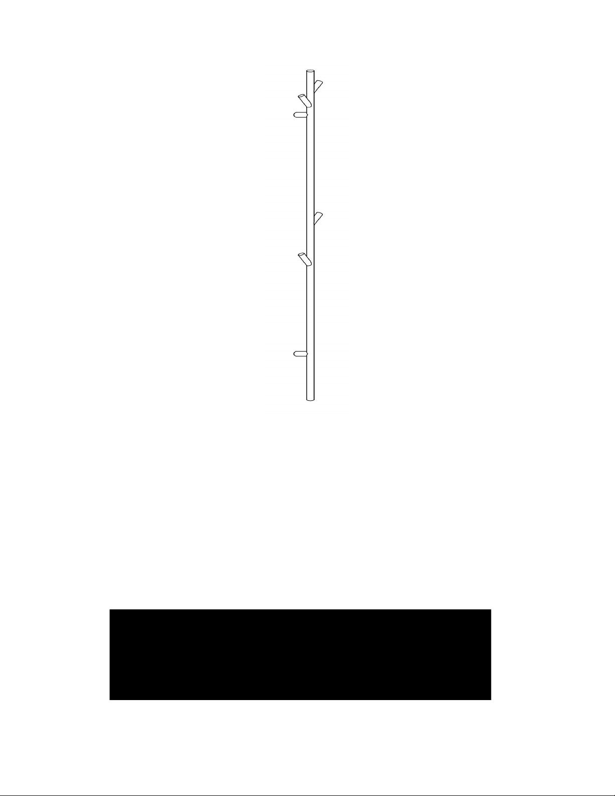
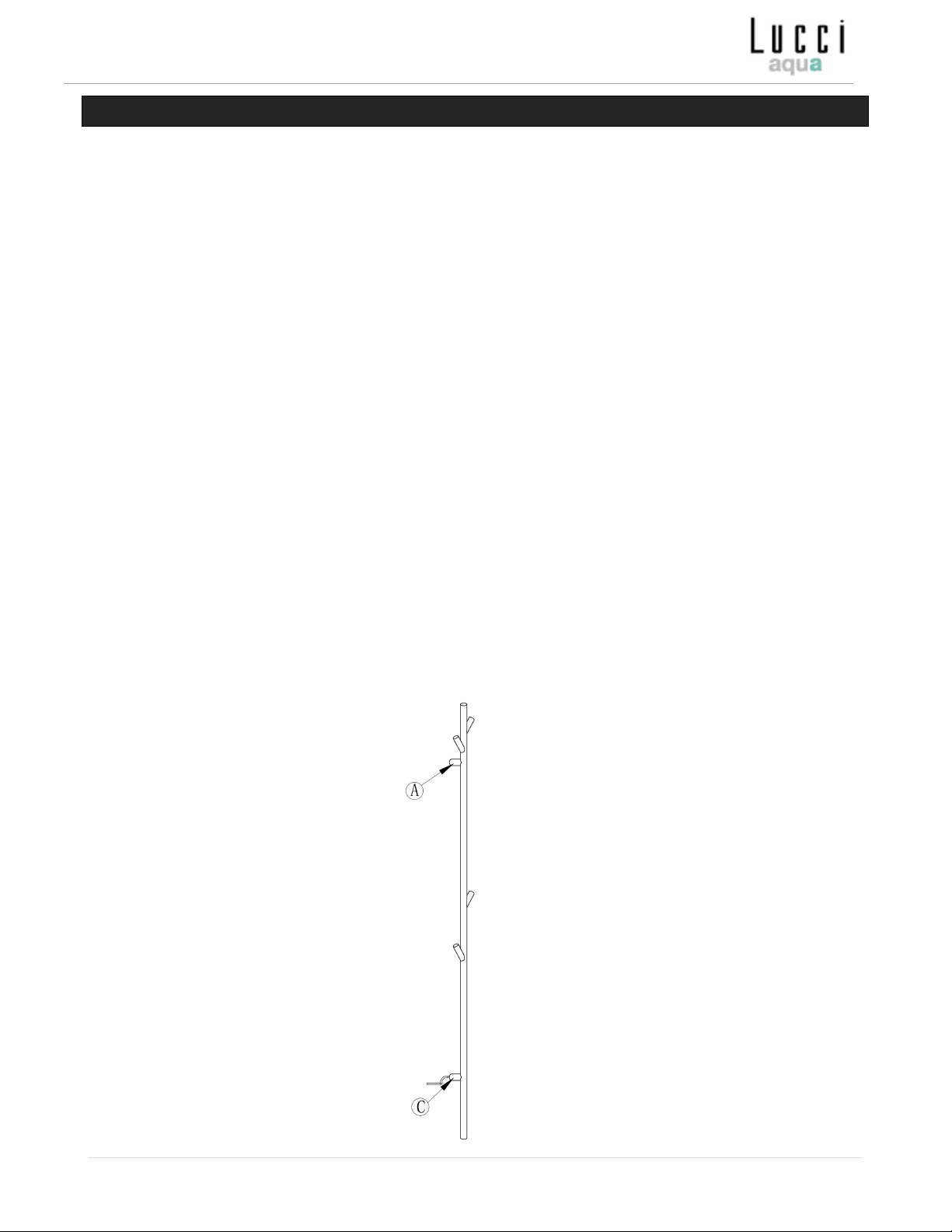
Installation Instructions
10 | P a g e
LUCCI WARRANTY DETAIL
LUCCI WARRANTY HOTLINE- 1800 602 243
THIS WARRANTY IS VALID IN AUSTRALIA ONLY
In the event where servicing is required, please call the Lucci Product Warranty Hotline on 1800 602 243 between 9 am
& 5 pm (EST) Monday to Friday. Please make sure you have all the product details filled out at the end of the manual
before making the call.
Every Lucci product is thoroughly inspected and tested before being released for sale. In addition to any warranty rights
or conditions under statutory regulations, Lucci warrants all of its products against defective workmanship and faulty
materials for twelve (12) months from the date of purchase. Lucci undertakes, at its option, to repair or replace, free of
charge, each product or part thereof on condition that;
1. The product or relevant part has not been subjected to misuse, neglect, or being involved in an accident.
2. The repairs are not required as a result of normal wear and tear.
3. The product was installed by a licensed electrical contractor.
4. A copy of the original receipt of purchase is presented.
5. A 12-month warranty applies when used in any non-domestic applications.
6. This warranty does not cover stains, scratch and scuff marks, or dents if the product is purchased through a
factory outlet or to refurbished items.
Our goods come with guarantees that cannot be excluded under the Australian Consumer Law. You are entitled to a
replacement or refund for a major failure and compensation for any other reasonably foreseeable loss or damage. You
are also entitled to have the goods repaired or replaced if the goods fail to be of acceptable quality and the failure does
not amount to a major failure.
Lucci Design cannot be held responsible for any repair other than those carried out by it or one of its Authorised
Service Agents. Please keep this warranty information in a safe place. This information must be produced in the
event of service being required.
Distributed by:
Beacon Lighting
140 Fulton Drive
Derrimut, Victoria, 3026
Australia
Ph +613 9368 1000
Email: warranty@beaconlighting.com.au