Lucoro Broadcast FMTX250 User manual

FMTX250
Stereo FM Transmitter with integrated
Audio Processor, Stereo Encoder and RDS Encoder
User Manua
WARNING!
This Transmitter is capab e of generating extreme y high RF
potentia . Touching interna parts, or the connected antenna
system, wi cause serious RF burns. Antenna systems shou d be
insta ed such that exposure by any person to RF fie ds cannot
exceed safe imits. The permitted imits vary from country to
country. Expert advice shou d be sought about the safe
insta ation of this transmission system.
RISK OF FIRE!
RF (Radio Frequency) energy cou d cause ignition of combustib e
surfaces during fau t conditions. Insta ation shou d be eft to
qua ified personne . RF can cause burns to skin. Ensure antenna
systems and feeder cab es are not situated near, or cou d fa
onto, any combustib e surface.

IMPORTANT!
A ways reduce the RF Output power to minimum before changing
the transmission frequency. Once the new frequency is active,
s ow y increase the RF output power contro to provide the
required power output eve .
WARNING!
Never operate this device without a suitab e 50 ohm oad
connected to the RF OUTPUT socket, or without a suitab y
insta ed and matched antenna system connected. A though the
output of this transmitter is protected against antenna oad
fau ts, MIS-OPERATION MAY RESULT IN DAMAGE NOT COVERED
BY ANY WARRANTY.
IMPORTANT!
Correct operation of the coo ing fans in this product is vita to
re iab e continuous operation. Schedu e bi-annua maintenance
checks. We strong y advise the use of a standby transmitter
system for use during maintenance events or fau t conditions, to
prevent pro onged breaks in transmission.
IMPORTANT!
When cyc ing the power off, then on, ensure that the transmitter
is off for at east 10 seconds before re-app ying power, to a ow
the interna circuits time to fu y reset. Fai ure to do so may resu t
in no RF output (PLL fai safe mode).
Consideration shou d be given to fitting a suitab y rated UPS if
power interruptions are ike y. Simi ar y, te emetry reset of power
may be advisab e for transmitters in remote areas, or having
restricted access arrangements.

The FMTX250 is a fu y integrated 125W Stereo FM broadcast system
with audio processing, stereo encoder and RDS encoder in a sing e,
high y compact product.
The audio processor provides inte igent Automatic Gain Contro , mu ti-
band compressor/ imiters, p us c ipping and DSP 15KHz fi tering.
The FMTX250 a so boasts a high qua ity Stereo Encoder section, for
perfect audio separation and detai .
The integra RDS encoder uses direct digita waveform synthesis for
c ean, perfect
generation of the 57kHz subcarrier. As we as PS (station
name) information, extended features - inc uding RadioTEXT,
A ternative Frequency and Traffic Announcement content - are a so
broadcast. Being standa one, a dedicated computer or data feed are
not required. Periodic content updates are easi y performed via the
transmitter’s USB port, using a Windows™ Laptop or PC. Free software
is avai ab e at https:// ucorobroadcast.com/support
At the heart of the FMTX250 is a high qua ity PLL modu ator, and the RF
Power Amp ifier uses the atest high-gain Enhancement Mode MOSFET
device, achieving new eve s of efficiency and re iabi ity.
TTL remote monitoring and switching a ows the FMTX250 to be easi y
integrated into automated back-up app ications. An audio si ence
a arm, p us remote RDS TA contro are a so provided.
These instructions shou d be read in fu before the transmitter is
operated.
The safety and operating instructions shou d be retained for future
reference.
A warnings on the transmitter and in the operating instructions
shou d be adhered to.
In
troduction
Before operating

A operation and user instructions shou d be fo owed.
Use of this device into a radiating antenna requires a va id icence from
a Spectrum Management Authority in most countries.
Use of this device as part of a transmission system, or combined
transmission system not specified by the manufacturer, may require
further testing to ensure that it remains comp iant with the essentia
requirements and other re evant provisions of current EU Low Vo tage,
EMC and Radio Equipment Directives. Approva and c earance from the
Spectrum Management Authority may a so be required.
Insta ation must adhere to safety regu ations and the requirements of
the re evant authorities. We recommend that at east two peop e are
present during insta ation. Keep a fi e containing insta ation
instructions and p ans, inc uding detai s of the transmission system
(antennas, feeders, fi ters, etc) and operating instructions for a
equipment at the transmission site at a times. Disp ay posters
detai ing first aid treatment and treatment for e ectrica shock, a ong
with te ephone numbers for contacting the emergency services in the
event of persona injury.
Ensure antenna system ightning strike protection is in p ace.
To reduce the risk of e ectrica shock, do not remove the cover, or any
screws. There are no user serviceab e parts inside; refer servicing to
qua ified personne .
Do not expose this app iance to rain or moisture. The transmitter
shou d not be used near water. Care shou d be taken so that objects
do not fa - and iquids are not spi ed - into the enc osure through
openings.
To reduce the risk of fire, a ways rep ace fuses with the same type and
rating.
The transmitter shou d be mounted into a we -venti ated standard 19
inch equipment rack, using s ide supports. It shou d be situated so that
its ocation or position does not interfere with its proper venti ation.
The transmitter shou d be situated away from heat sources.
The transmitter shou d be connected to a power supp y on y of the
type described in the operating instructions or as marked on the unit.
Precautions shou d be taken so that the grounding or po arisation of
this app iance is not defeated.

The unit shou d be c eaned on y as recommended by the
manufacturer.
The transmitter shou d be serviced by qua ified service personne if it
does not appear to operate norma y, exhibits a marked change in
performance, has been subjected to shock, damage, moisture, or if
foreign objects have ingressed.
The user shou d not attempt to service the transmitter beyond that
which is described in the Operating Instructions. A other servicing
shou d be referred to qua ified service personne .
This app iance may become warm under norma operating conditions.
Recyc e according to WEEE regu ations.
1. SYSTEM Status LED. Green indicates correct operation, red indicates
a system error requiring urgent further investigation.
2. DOWN Push-button. Press this contro to navigate the LCD menu.
3. ENTER Push-button. Press this contro to navigate the LCD menu.
4. UP Push-button. Press this contro to navigate the LCD menu.
Contro s and Connectors

5. AF MON BNC connector for monitoring of the input to the
modu ator (baseband MPX spectrum).
6. RF MON BNC connector for monitoring of the RF output. Output
eve wi be the RF output eve attenuated by approximate y 40dB. Not
to be used for measurement of harmonics.
7. RF OUT 'N' Socket. Connect a matched, pre-tested antenna system
with a return oss of >14dB to this socket. Ensure a parts of the feeder
and antenna system are rated for 300W or above.
8. RF ADJ Use a suitab e trimmer too to adjust the RF output power
eve , (RF FWD on the disp ay). Never set to above the 250W maximum
rated output power.
9. AUDIO IN (LEFT) XLR Socket. Connect a +8dB 600ohm ba anced
audio feed to this socket.
10. AUDIO IN (RIGHT) XLR Socket. Connect a +8dB 600ohm ba anced
audio feed to this socket.
11. REMOTE 9-pin D-sub Fema e. Remote contro and monitor inputs
and outputs are avai ab e on this connector:
Pin 1. Ref ected Power A arm. TTL ogic ow during norma
operation. F oats high to indicate a high eve of ref ected power
(critica antenna mis-match) has been detected.
Pin 2. Forward Power a arm. TTL ogic ow during norma
operation. F oats high to indicate RF output has fai ed.
Pin 3. Audio fai ure a arm. TTL ogic ow during norma operation.
F oats high to indicate more than one minute (approx) of no
signa detected on the XLR audio inputs.
Pin 4. Temperature a arm. TTL ogic ow during norma
operation. F oats high to indicate over-temperature condition
has occurred.
Pin 5. RDS TA Contro . Supp ying between 5 and 12V this pin to
(with reference to chassis ground potentia ) wi activate the RDS
TA (Traffic Announcement). Primari y used in automated
changeover systems. (Option at time of ordering)

Pin 9. RF Mute Contro . Supp ying between 5 and 12V this pin to
(with reference to chassis ground potentia ) wi mute the RF
output. Primari y used in automated changeover systems.
Pin 6, 7, 8 GND connection, at chassis earth potentia .
The above ‘Open Co ector’ outputs are capab e of operation up to 50V
and sinking a current of 75mA maximum. The norma y high, (ie. ‘pu
ow’ upon a arm condition) provides inherent ‘power fai ure’ or ‘cab e
connection fai ure’ signa ing.
12. USB Socket. When updates to the RDS content are required,
connect a Windows
TM
PC (running the manufacturer’s free software
app ication) to this port. Use a high-qua ity USB cab e, of 1metre or ess
in ength.
13. MPX IN. If using an externa processor and RDS encoder, or a
baseband MPX Studio-Transmitter Link, connect to this BNC. Adjust the
output eve of the externa equipment to provide the correct
modu ation eve (requires test equipment).
14. MPX OUT. To broadcast audio connected to the transmitter, with
the interna audio processing and RDS data app ied, connect the
supp ied patch ead between this ‘MPX OUT’ socket and the ‘MPX IN’
BNC socket.
15. POWER. Connect a power ead with an IEC C13 connector (and a 3
amp fuse in the p ug or at the distribution pane ) to this socket. Two T2
amp (time de ay) fuses are fitted within this connector’s Fuse carrier.
16. EARTH. Grounding connection point (M4 stud and bo t).
Connect a suitab e rated test oad to the RF OUPUT socket before
connecting the unit to mains power. IMPORTANT! FAILURE TO DO SO
MAY RESULT IN DAMAGE NOT COVERED BY WARRANTY.
Power-up the unit and reduce the output power (using the rear pane
RF OUTPUT POWER ADJUST contro ) to the owest eve .
Insta ation

Using the front pane disp ay and buttons, set the desired transmission
frequency.
Power down the unit, wait a few seconds and, whi st pressing
ENTER for 5 seconds, power up the unit. After a short whi e, the
current y set frequency wi appear on the disp ay. Use the UP
and DOWN buttons to se ect the desired frequency. Press
ENTER to store. The new frequency wi f ash rapid y to indicate
that it is now stored. The unit wi begin its boot process and,
after a few seconds the disp ay wi return to norma mode, and
the transmitter wi begin broadcasting.
The factory wi have set the deviation, RDS and pi ot injection eve s.
They shou d need no further adjustment. However, if abso ute y
necessary, these can be changed as fo ows (NOT recommended):
To adjust the deviation eve , use a suitab e trimmer too
carefu y adjust the front pane “DEV ADJ”. This is a sing e turn
contro . The eve can be varied by approximate y ±10%. Pi ot
and RDS subcarrier eve s wi a so change.
To adjust the RDS injection eve , ocate the circuit board
“MPX/RDS” on the inside rear pane . Adjust trimmer “VR1 (RDS)”
to set the desired RDS injection eve . This is a mu titurn contro .
ELECTRIC SHOCK AND RF BURN HAZARD! DISCONNECT THE
POWER BEFORE REMOVING ANY COVERS.
Take GREAT CARE not to adjust any other circuit trimmer
contro s. Even the s ightest adjustment WILL degrade
performance and may cause non-comp iance to broadcast
regu ations.
Connect Left and Right Audio to the rear pane XLR connectors, and
adjust the source eve so that maximum audio peaks register just
be ow the peak section of the front pane audio eve bar graph disp ay.
Use ordinary programme materia , rather than test tones. Ensure the
MPX OUT to MPX IN oop-though patch ead (BNC to BNC) is
connected.
Once a settings are correct, power down the unit. Disconnect the test
oad and connect to the antenna. Power up the unit and increase the
RF Power (using the rear pane RF ADJ contro ) to the desired eve , not
exceeding 100W.
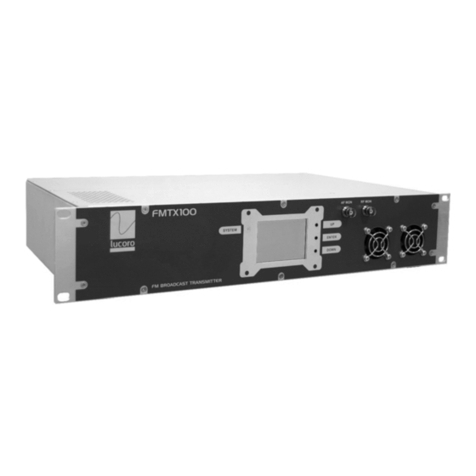
The FMTX250 is designed for continuous re iab e transmission,
however the fans must be periodica y checked for correct operation
and free airf ow.
The front pane disp ay shows the transmission frequency, forward
power eve ( FWD ), ref ected power eve ( REF ) and audio input
eve s (ahead of any audio processing).
Audio eve s wi be optimised by the Audio Processor, however regu ar
checks of audio eve s entering the transmitter are advised.
Correct operation is confirmed by a front pane green STATUS LED.
Shou d this turn red, the transmission system may shut down its RF
output and wi , in any case, require URGENT attention.
The LCD disp ay shows a main parameters so no further menus are
provided or required (except frequency setting detai ed above). During
norma operation, therefore, the menu buttons do not have
any function.
The fo owing are LCD disp ay fau t indicators and their meaning:
Operation

TEMP! The system is running too hot and has shut down the RF
output as a safety precaution. Check the fans for correct
operation. A so check the antenna system, inc uding a cab ing
(and/or fi ters and/or combiners where fitted) for correct
operation. The FWD! indicator (see be ow) wi a so show and the
standby transmission system (where used) wi have activated
(TTL contro ).
REF!! The system has detected a fau t in the antenna system
and has shut down the RF output as a safety precaution. Check
the antenna system, inc uding a cab ing (and/or fi ters and/or
combiners where fitted) for correct operation. The FWD!
indicator (see be ow) wi a so show and the standby
transmission system (where used) wi have activated (TTL
contro ).
FWD! The system has detected there is no forward power. This
may be due to one or both of the above symptoms, due to a PLL
fai ure, or due to excessive power setting. The standby
transmission system (where used) wi have activated (TTL
contro ).
The RDS content can be periodica y updated using a Windows™
computer and USB programming device (purchased separate y)
connected to the RDS Programming Port connector on the rear pane .
Fo ow the instructions provided with the RDS Programming Device
and software.
Ensure air vents and interna air tunne s are kept free from dust during
operation.
The coo ing fans shou d be rep aced after 40,000 hours of cumu ative
operation. This ife rating is for guidance on y and is subject to idea
environmenta operating conditions. Immediate y rep ace any fan that
fai s or becomes s ow or noisy, immediate y. Rep acement fan
assemb ies with wiring oom and mating connector are avai ab e from
the manufacturer. It is recommended that rep acement work must be
carried out by the manufacturer or an approved agent.

EC Dec aration of Conformity to R&TTE Directive 1999/5/EC
We, Lucoro Broadcast
C ay Pit Lane
Roec iffe
York
YO51 9FS
hereby take so e responsibi ity to confirm that the product:
FMTX100, FMTX250
(and versions thereof with M and RBRX suffix)
which this dec aration refers to, conforms to a app icab e
requirements of EU Directive 2014/53/EU and is CE marked
according y:
Low Vo tage Directive 2014/35/EU:
IEC 60950-1:2005/A2:2013
Safety Requirements for equipment < 600V
EMC Directive 2014/30/EU:
ETSI EN301 489-53 v1.1.0 (ETSI EN301 489-1 v2.1.1
ERM/EMC for Radio Equipment
Specific Conditions for FM Transmitters (Part 11)
Radio Equipment Directive 2014/53/EU:
ETSI EN302018-2 v2.1.1
Transmitting Equipment for FM Radio Broadcasting service
The fo owing operation conditions and insta ation arrangements have
to be presumed:
(i) According to Operating Instruction Manua
(ii) Connected ead engths of 2 metres or ess
M. O’Rorke, Director
September 2020

RF:
Frequency range 87.5 to 108.00MHz
Frequency stabi ity Better than ±200Hz
Output power 30 - 250W
Harmonic & spurious output -75dBc typica
AM Noise <0.5% @ ±40kHz deviation
THD <0.15%@ ±75KHz deviation
RF output connector ‘N’ type (F)
Monitoring:
RF BNC (F) -40dB 50 ohms
MPX BNC (F) 1V P-P 10K ohms
Audio Interface:
Audio Input Leve +8dBu for ±75KHz deviation
Audio Input Impedance 600 Ohms
Audio input connectors XLR (F)
RDS:
Groups 0A & 2A (others on request)
Power Supp y:
Input AC 100V to 250V (50/60 Hz)
Consumption (maximum RF output) 550W (230V 50Hz)
Mechanica :
Size (mm) 2U 88 (H) x 482 (W) x 290 (D)
Weight 5kg
Temperature 0ºC to +42ºC
Humidity 95% (re ative non-condensing)
We reserve the right to a ter specifications without notice. E&OE.
Technica Specifications

WEEE - Waste E ectrica and E ectronic Equipment
The equipment that you bought has required the extraction and use of
natura resources for its production. It may contain hazardous
substances that cou d impact hea th and the environment.
In order to avoid the dissemination of those substances in our
environment and to diminish the pressure on the natura resources,
we encourage you to use the appropriate take-back systems. Those
systems wi reuse or recyc e most of the materia s of your end ife
equipment in a sound way.
The crossed-out whee ed bin symbo invites you to use those systems.
If you need more information on the co ection, reuse and recyc ing
systems, p ease contact your oca or regiona waste administration.
IMPORTANT!
NO REPRESENTATIONS OR WARRANTIES, EITHER EXPRESS OR IMPLIED,
OF MERCHANTABILITY, FITNESS FOR A PARTICULAR PURPOSE OR OF
ANY OTHER NATURE ARE MADE WITH RESPECT TO THIS PRODUCT. Do
not misconstrue any information as our recommendation to use any
product, process, or equipment in conf ict with any regu atory authority
or patent.
Ensure comp iance with a app icab e safety requirements when
insta ing or using this equipment, and operate in accordance with oca
aws governing the use of radio transmission equipment.
No part of this document may be reproduced or transmitted, in any
form, by any means, without prior written consent of the Lucoro
Broadcast.

Lucoro Broadcast sha not be iab e for any direct, indirect, incidenta ,
consequentia or other damage or oss a eged in connection with the
supp y or use of this product.
The information contained in this document is subject to change
without notice. Lucoro Broadcast makes no warranty of any kind with
respect to this information. Lucoro Broadcast specifica y disc aims the
imp ied warranty of merchantabi ity and fitness for a particu ar
purpose.
Lucoro Broadcast
C ay Pit Lane
Roec iffe
York
YO51 9FS
Te ephone 01423 313550
Te ephone (Internationa ) +44 1423 313550
Enquiries: sa es@ ucorobroadcast.com
Table of contents
Other Lucoro Broadcast Transmitter manuals

Lucoro Broadcast
Lucoro Broadcast FMTX50RBRX User manual

Lucoro Broadcast
Lucoro Broadcast FMTX1 User manual

Lucoro Broadcast
Lucoro Broadcast FMTX250M User manual

Lucoro Broadcast
Lucoro Broadcast FMTX100 User manual

Lucoro Broadcast
Lucoro Broadcast FMTX100M User manual

Lucoro Broadcast
Lucoro Broadcast FMTX50M User manual

Lucoro Broadcast
Lucoro Broadcast FMTX100RBRX User manual