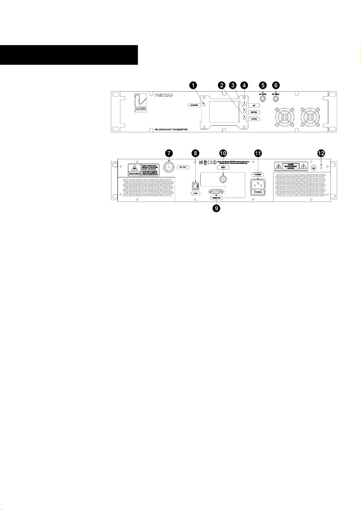
Power-up the unit and reduce the output power (usin the rear panel
RF OUTPUT POWER ADJUST control) to the lowest level.
Usin the front panel display and buttons, set the desired transmission
frequency.
Power down the unit, wait a few seconds and, whilst pressin
ENTER for 5 seconds, power up the unit. After a short while, the
currently set frequency will appear on the display. Use the UP
and DOWN buttons to select the desired frequency. Press
ENTER to store. The new frequency will flash rapidly to indicate
that it is now stored. The unit will be in its boot process and,
after a few seconds the display will return to normal mode, and
the transmitter will be in broadcastin .
Chan in transmission frequency may affect the deviation level sli htly.
It is important that the deviation levels are checked.
Connect the baseband multiplex si nal to the rear panel BNC
connector. Usin a calibrated deviation meter, or FM analyser,
adjust the source level so that maximum deviation peaks
re ister just below ±75kHz. The front panel DEV level bar raph
display shows the approximate relation of MPX input level to
deviation.
Once all settin s are correct, power down the unit. Disconnect the test
load and connect to the antenna. Power up the unit and increase the
RF Power (usin the rear panel RF ADJ control) to the desired level, not
exceedin 50W.
The FMTX50M is desi ned for continuous reliable transmission,
however the fans must be periodically checked for correct operation
and free airflow.
The front panel display shows the transmission frequency, forward
power level ( FWD ), reflected power level ( REF ) and multiplex input
levels.
Correct operation is confirmed by a front panel reen STATUS LED.
Should this turn red, the transmission system may shut down its RF
output and will, in any case, require URGENT attention.