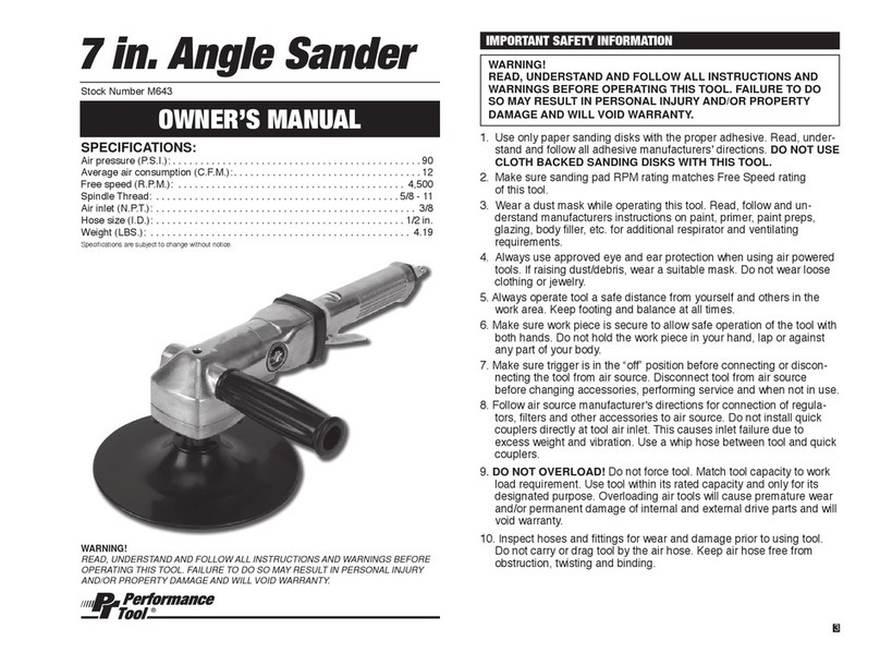
Lukas AM 07/100 GH User manual

- AM 07/100 GH -Stand: 27.10.2008
Bedienungsanleitung
Operation Instructions
AM 07/100 GH

- AM 07/100 GH -Stand: 27.10.2008
1
2
3
4
5
6
7
8
9
Appendix
A
B
C
D
Introduction
Technical data
Commissionin
g
Usa
g
e
Mountin
g
the
g
rindin
g
wheel
Safet
y
Instructions
Maintenance Instructions
Warrant
y
Spare Part List
Technical Drawings
Service and Manufacturer's Address
Declaration of Conformit
y
Warranty Certificate
12
12
13
14
14
15
16
17
18
20
21
22
23
Index
11

12 - AM 07/100 GH -Stand: 27.10.2008
1. Introduction
The AM 07/100 is a pneumatic power tool reflecting state-of-the-art technology.
It is driven by a vane air motor using compressed air.
The integral speed controller keeps the rotation at a constant speed.
This power tool is qualified exclusively for manual radial grinding with conical grinding
wheels type 4 according to DIN ISO 603-12 with a maximum diameter of 125 mm
and a minimum permissible operating speed of 50 m/s.
The vibration and sound values specified in the technical data were measured
according to EN 28662-1 and EN ISO 8662-13 as well as prEN ISO 15744.
Prior to using the power tool you should become familiar with
the operation instructions.
The power tool must not be commissioned before the safety
information for the operator has been read.
2. Technical Data
Type: straight die grinder with lever valve
max. RPM: 7.600 min-1 - 10%
Service pressure: 0,63 MPa
Nomials hose diameter: 13 mm
Weight: approx.. 3,8 kg
Dimensions: ca. ∅74 x 530 mm
Output: 1,5 KW
Air Consumption: approx. 1,55 m³/min.
Noise levell: 85 dB(A) max.

13 - AM 07/100 GH -Stand: 27.10.2008
Vibration acelleration: < 2,5 m/s2
Drive: Vane Air Motor
Accessories included:
- 1 allen key Ø 6mm
Optional Equipment:
3. Commissioning
The power tool must only be connected to the compressed air network using a
pressure reducer (combination of water separator – pressure control valve –
lubricator). The nominal diameter of the pressure reducer must comply at least with
the hose diameter specified in the technical data. The pressure control valve must be
set to the value of 0.63 MPa.
The pressure reducer must be installed at the working height of the power tool or
above.
The compressed air hose supplied with the machine must be directly connected to
the pressure reducer and must not be lengthened.
The lubricator must be adjusted so as to supply approx. 3 drips per minute at a
pressure of 0,63 MPa. Only oil types quoted in the table below may be used.
In the case of a prolonged period without use (e.g. overnight), the machine must be
disconnected from the compressed air system.

14 - AM 07/100 GH -Stand: 27.10.2008
Suitable oil types Viscosity
Festo Spezialöl
Aral Vitam GF 22
Esso Nuto H 22
Mobil DTE 22
BP Energol HLP 22
Shell Tellus C 22
22 mm²/s(=cSt) bei 40°C
ISO-Klasse VG 22
nach ISO 3448
4. Usage
Only conical grinding wheels type 4 according to DIN ISO 603-12 with a maximum di-
ameter of 125 mm and a minimum permissible operating speed of 50 m/s are allo-
wed for usage. The use of cutting discs as well as groove and profile milling cutters is
prohibited.
Only use tools with a permissible operating speed of at least the maximum speed of
the power tool.
Always ensure that the main load is transmitted in a radial direction (i.e. on the tool
circumference) and not in an axial direction to the power tool.
Before changing a tool or undoing the compressed air hose, the power tool must be
disconnected from the compressed air supply.
5. Mounting the grinding wheel
Before mounting a grinding wheel the power tool must be disconnected from the
compressed air supply.
The grinding wheel must be checked for damages. Do not use damaged wheels.

15 - AM 07/100 GH -Stand: 27.10.2008
For mounting the grinding wheel the flanges attached must be used. The use of blot-
ters is prohibited.
Before inserting the wheel the flanges must be cleaned and checked for damages.
Damaged flanges must be exchanged.
Thr grinding wheel must be clamped firmly by the use of the allen key attached.
Check the free rotation of the wheel prior to starting.
After a tool change, the power tool must be test run in a safe place (e.g., underneath
the work bench) with the tool clamped in position.
6. Safety Instructions
The power tool must not be operated with damaged or incorrectly clamped tools as
this may cause vibration.
When machining certain materials, dust and vapour may occur which result in an
explosive atmosphere. The power tool must not be used in an explosive atmosphere.
After switching off, the power tool may continue to run for a few seconds. The tool
must not be touched until it is at a standstill.
In the case of failure of the compressed air supply, the power tool must be switched
off at the valve so as to prevent uncontrolled start-up when the pressure returns.
Compressed air hoses may whip uncontrollably and may cause serious injury.
Energy retained in the form of compressed air bears a potential safety risk.
A maximum air pressure of 0,63 MPar must not be exceeded during power tool

16 - AM 07/100 GH -Stand: 27.10.2008
operation. The power tool must only be connected using a pressure control valve.
Make sure that loose clothing and long hair are not ensnared by the power tool when
in operation.
To protect the operator, he or she must wear goggles and ear protection during
operation. It is recommended that gloves and suitable protective clothing is worn.
Depending on the materials to be machined, personal protection equipment and dust
extraction may have to be used.
All operators using the power tool must abide by the accident prevention regulations
as well as the FEPA safety code.
7. Maintenance Instructions
Maintenance work on this power tool may only be carried out by specialists.
After each maintenance check, the power tool must be tested for speed and
vibrations.
The power tools speed must be checked at regular intervals using suitable inspection
equipment.
Compressed air hoses must be checked at regular intervals for damage and leakage.
Damaged hoses must be replaced.
The pressure reducer must be checked at regular intervals and topped up with oil as
needed.

8. Warranty
This power tool is subject to a 6 month's guarantee from the date of sale. The war-
ranty applies to defects that demonstrably result from material, design or workmans-
hip. Further claims, in particular rescission, reduction or replacement due to direct or
indirect damages shall be excluded.
The warranty will be void if during the warranty period modifications or repairs are
undertaken by any repair shop not authorised by us.
Our warranty only applies in the case of correct use of the power tool. It does not co-
ver natural wear and tear as well as defects or damage directly or indirectly resulting
from misuse, operating errors or transport.
A guarantee claim may only be submitted using the duly completed warranty certifi-
cate for this power tool.
17 - AM 07/100 GH -Stand: 27.10.2008

18 - AMIN 45 GD -Stand: 27.10.2008 18 - AM 07/100 GH -Stand: 27.10.2008
Pos. Description LE-Item-Nr.
1
4
HOUSING
SPRING WASHER
A871700100065
A871500176308
5
6
7
8
SPINDLE
IDENTFICATION PLATE
A875500302024
A874300904518
WASHER
FACE OUTLET
A871400603014
A875100203017
9
10
12
13
VANE SET
FACE INLET
A872900204016
A875100202020
SPRING
WEIGHT
A871500605020
A871800208027
14
15
16
17
LEVER UNIT
HANDLE BAR
A872000014020
A871900011536
FLANGE FRONT CONICAL
FLANGE BACK CONICAL
A875900505015
A875900504019
18
19
20
21
RING
COUPLING
A873500600034
A872700306006
SPRING WASHER
ROTOT
A871500604021
A873800201020
22
23
24
25
STATOR
INLET
A874900200019
A871400616006
SWIVEL NUT
REGULATOR UNIT
A873100501021
A873400012002
27
28
29
30
WASHER
VALVE SEAT
A874100100240
A875300600078
VALVE UNIT
SPRING
A875301609008
A871500605014
31
33
34
35
FILTER
REDUCER
A874600405013
A873100501023
NOZZLE
O-RING SEALING 22 x 2
A875200408017
A8735012202
36
37
38
39
O-RING SEALING 24 x 2
O-RING SEALING 14 x 2
A8735012402
A873501140201
SCREW M3 x 25
NUT M3
A875700612094
A873100492003
9. Spare Part List

19 - AMIN 45 GD -Stand: 27.10.2008 19 - AM 07/100 GH -Stand: 27.10.2008
Pos. Description LE-Item-Nr.
40
41
COVER
SNAP RING 15 x 1 DIN 472
A871300611013
A8735021501
43
44
45
46
WASHER 8,8 DIN 125
RING
A8741001740
A873500600034
BALL BEARING 6002 - 2Z
A872800600201
A872800620202
47
48
49
52
BALL BEARING 6204 - 2Z
BALL BEARING 6203 - 2Z
A872800620402
A872800620303
PIN 2 x 12 DIN 6325
SCREW M8 x 30
A8750000212
A87570011435201
54
55
56
84
SNAP RING 12 x 1 DIN 471
PIN 2 x 8 DIN 6325
A873502120101
A8750000208
SCREW M6 x 8
KEY
A875700811024
A876100056003
Pos.
902
Description LE-Item-Nr.
ALLEN KEY SW6 A876106230710
Optional Equipment
Pos. Description LE-Item-Nr.
1000 WHEEL GUARD A874500014062

20 - AM 07/100 GH -Stand: 27.10.2008
A. Technische Zeichnungen / Technical Drawings

21 - AM 07/100 GH -Stand: 27.10.2008
B. Service- und Herstelleranschrift
Service and Manufacturer's Address
Bitte senden Sie die Maschine für die Durchführung von Instandhal-
tungsarbeiten an:
For repair, please return machine to:
LUKAS-ERZETT
Vereinigte Schleif- und Fräswerkzeugfabriken GmbH & Co. KG
Ohl 1-3
D-51766 Engelskirchen
Tel. (0 22 63) 84 - 0
Fax (0 22 63) 84 - 3 00

22 - AM 07/100 GH -Stand: 27.10.2008
Gemäß Anhang II A der EG-Maschinen-Richtli-
nie 98/37/EG (MaschR)
Engelskirchen, 20.2.2005
LUKAS-ERZETT Vereinigte Schleif- und
Fräswerkzeugfabriken GmbH & Co. KG
Paul Lehnard
(Geschäftsführer / Managing Director)
AM 07/100 GH
C. EG-Konformitätserklärung / Declaration of
conformity
Lukas
According to annex II A of the Machinery
Directive 98/37/EC
Hiermit erklären wir, dass die Bauart
der pneumatischen Antriebsmaschine:
We hereby declare that the design of
the pneumatic power tool:
Fabrikat / Manufacturer:
Typ / Type:
Serien-Nr. / Serial-No.:
Baujahr /Year of construction:
folgenden einschlägigen Bestimmun-
gen entspricht: complies with the following applicable
regulations:
MaschinenRL 98/37/EG / Machinery Directive 98/37/EC
Angewendete harmonisierte europäi-
sche Normen
LUKAS-ERZETT
Vereinigte Schleif- und Fräswerkzeugfabriken GmbH & Co. KG
Ohl 1-3
D-51766 Engelskirchen
Tel. +49 (0) 22 63 84 - 0
Fax. +49
(
0
)
22 63 84 - 300
Applied harmonized European stan-
dards
EN 292 – 1 ; EN 1050; EN 292 – 2 + A1; EN 792 - 9

23 - AM 07/100 GH -Stand: 27.10.2008
D. Garantiekarte / Warranty Certificate
Wir leisten Garantie entsprechend unserer schriftlichen Garantieerklärung in der Be-
dienungsanleitung für einen Zeitraum von 6 Monaten ab unten eingetragenem
Auslieferungs-/Verkaufsdatum auf Mängel, die nachweislich von Material-,
Konstruktions- oder Verarbeitungsfehlern herrühren, für die Maschine
We give warranty according to our written declaration of warranty as quoted in the
operating instructions for a period of 6 months from the date of delivery / sale stated
below for defects that are demonstrably due to material, design or workmanship on
the power tool
Stempel / Stamp:
AM 07/100 GH
L U K A S - E R Z E T T
Vereinigte Schleif- und Fräswerk-
zeugfabriken GmbH & Co. KG
Postfach 1259 u. 1260
D - 5 1 7 5 2 Engelskirchen
Ohl 1 – 3
D - 5 1 7 6 6 Engelskirchen
Phone +49 (0) 2263/84-0
- Bei Garantieanspruch bitte mit der Maschine einsenden
- In case of warranty claims return card along with the power tool
Typ / Type:
Serien-Nr. / Serial-No.:
Auslieferungsdatum:
Date of delivery:
Verkaufsdatum:
Date of Sale:
siehe Rechnungsdatum
see date of invoice
This manual suits for next models
1
Table of contents
Other Lukas Nail Gun manuals