LumaSense technologies Innova-1409 User manual

__
BI7717-11
Service Manual
Multipoint Sampler
Innova-1409

_______________________________________________________________________________________
BI7717-11 1409 Multipoint Sampler LumaSense Technologies A/S
Service Manual Page 2 of 28

Index
_______________________________________________________________________________________
BI7717-11 1409 Multipoint Sampler LumaSense Technologies A/S
Service Manual Page 3 of 28
Index
Index 3
Safety Consideration 4
5
Chapter 1 Introduction 6
1.1 Introduction to the Service manual 7
1.2 Introduction to the 1409 7
1.2.1 The Sampler System 7
1.2.2 Front Panel 9
1.2.3 Back Panel 10
1.2.4 Interconnection diagram 11
Chapter 2 Service Software BZ7006 12
2.1 Installation of the Service software BZ7006 13
2.1.1 System requirements 13
2.1.2 Installation of the program 13
2.2 Testing procedure 14
2.2.1 Starting the program 14
2.2.2 Connection of the 1409 14
2.2.3 1409 Multipoint Sampler Id identification: 15
2.2.4 1409 Multipoint Sampler Configuration: 16
2.2.5 Testing the Sample valves 16
2.2.6 Reset 1409 17
2.2.7 1409 Multipoint Sampler Status: 17
2.3 Closing the program 17
Chapter 3 Mechanical parts and PCB’s 18
3.1 Mechanical parts and PCB 19
3.1.1 Power supply ZG0370A 19
3.1.2 Center manifold UM1119A 19
3.1.3 6 channels Sample manifold UM1120A 20
3.1.4 Multipoint Sampler PCB ZD0900A 21
Chapter 4 Parts replacements 22
4.1 Parts replacements 23
4.2 Fields replaceable parts. 26
4.3 Electrical drawing of ZD0900A 27

Safety Consideration
____________________________________________________________________
_______________________________________________________________________________________
BI7717-11 1409 Multipoint Sampler LumaSense Technologies A/S
Service Manual Page 4 of 28
Safety Consideration
July 2015

Safety Consideration
____________________________________________________________________
_______________________________________________________________________________________
BI7717-11 1409 Multipoint Sampler LumaSense Technologies A/S
Service Manual Page 5 of 28
SAFETY CONSIDERATIONS
PLEASE READ THESE SAFETY CONSIDERATIONS
CAREFULLY AND MAKE SURE YOU UNDERSTAND THEM
PROPERLY BEFORE YOU START OPERATING THE 1409
MULTIPOINT SAMPLER.
EXPLOSION HAZARD
THE 1409 MULTIPOINT SAMPLER IS NOT DESIGNED
FOR USE IN POTENTIALLY EXPLOSIVE
ENVIRONMENTS.
This means that the instrument must not be placed and operated in
an area with a potentially explosive atmosphere.
When monitoring potentially flammable or toxic gases it is essential
that:
1) the instrument itself is placed in a well-ventilated area outside the
potentially hazardous zone; and
2) a sufficiently long tube is connected to the “Sampler Waste Air
Outlet” so that the sampled gas is carried away to the open air or
to an extraction and/or filtration unit.
TO AVOID THE POSSIBILITY OF AN EXPLOSION, MONITORING OF
FLAMMABLE GASES IN EXPLOSIVE CONCENTRATIONS MUST
NEVER BE ATTEMPTED.
AVOID WATER CONDENSATION IN THE INSTRUMENT.
Liquids must be prevented from entering the instrument. It is therefore
important that warm humid gases be not drawn into a cold instrument
because condensation will take place. If such a situation is likely to
occur, you should ensure that the gases are drawn through water-trap
filters before they enter the sampler channels of the 1409. This will
remove water vapour in the gases and thus prevent condensation
within the instrument. The water-trap filter should be used in the
immediate environment of the instrument so it maintains either the
same temperature, or a lower temperature than the instrument.
Note: that some gases may be absorbed by the water trapped in the
filter. This will reduce the gases’ concentration.

Chapter 1
____________________________________________________________________
_______________________________________________________________________________________
BI7717-11 1409 Multipoint Sampler LumaSense Technologies A/S
Service Manual Page 6 of 28
Chapter 1
Introduction
July 2015

Chapter 1
____________________________________________________________________
_______________________________________________________________________________________
BI7717-11 1409 Multipoint Sampler LumaSense Technologies A/S
Service Manual Page 7 of 28
1.1 Introduction to the Service manual
This Service Manual is intended for the service and maintenance of the 1409
Multipoint Sampler, hereafter referred to as the 1409.
It will provide the service engineer with information about the operating
principle on a technical level and the use of the Service software BZ7006 for
fault finding and testing.
A Service Note that will be published on our web site, http://innova.lumasenseinc.com,
informs any product change that will impair the safety or performance of the
device.
The operation and maintenance procedures are fully described in the Technical Documentation
BE6037 delivered with the 1409 and the service technician must fully acquainted with the
operation of the instrument prior to any attempt to service it.
Due to the complexity of the 1409 the service and repair is only possible
on module level and only a few individual components are made available for
field service.
Handling of the electronic parts must be done with proper ESD equipment to
avoid any possibility of an electrostatic discharge to the components. Modules
returned to LumaSense Technologies A/S for repair/credit will be discarded if
not properly packed in ESD material.
1.2 Introduction to the 1409
1.2.1 The Sampler System
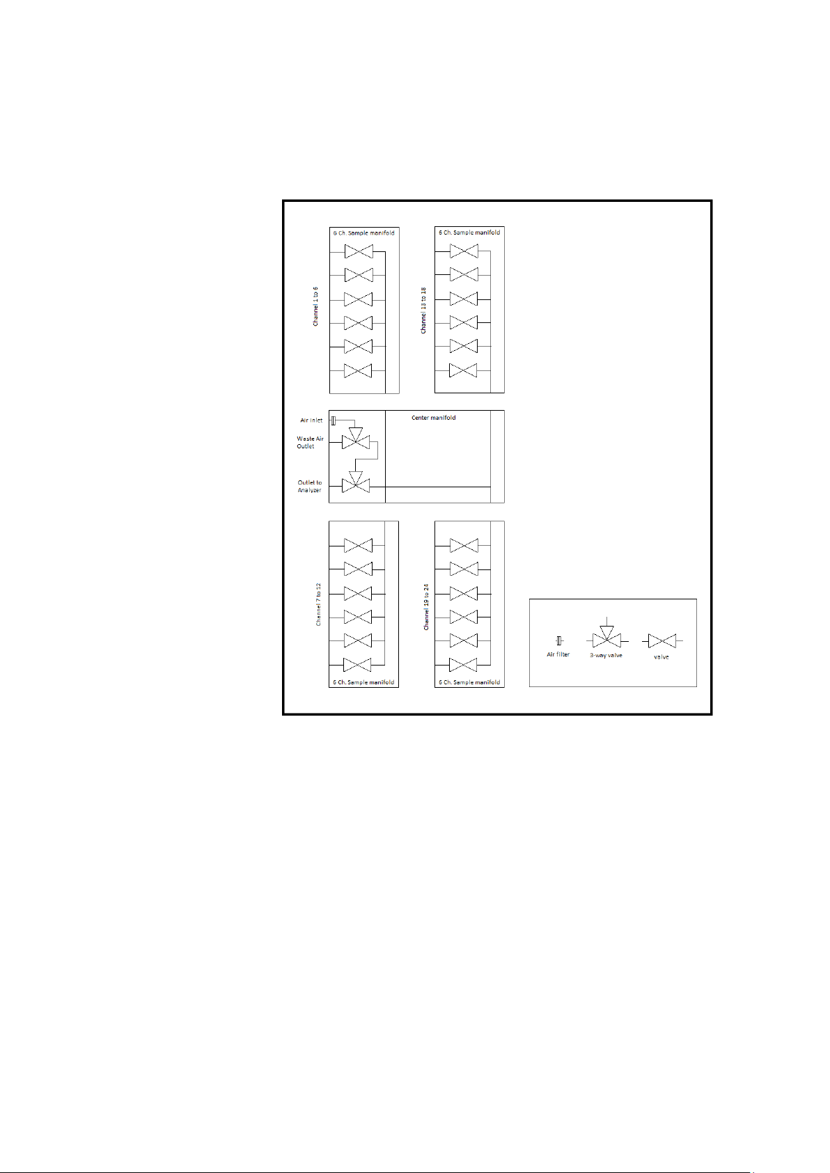
The pneumatic system of the 1409 is shown schematically in Fig.1.1. The sampler system is
constructed of stainless steel (AISI 316) to minimize adsorption of samples.The 1409 is
delivered with 6, 12, or 24 channels. All inlet channels are with a solenoid valve. Each inlet
channel has a tube-mounting stub on the back-plate of the 1409 to connect each channel to
the respective sampling point. The inlet channels converge into one; a three-way valve then
directs the gas sample to the Gas Monitor for analysis, or through the waste-air outlet on the
1409’s back-plate.
An external pump (optional) can be connected in the airway system to the waste air outlet.
The 1409’s sampler system functions efficiently, transporting gas samples from the sampling
point at approximately 4 metres per second. However, this speed depends on the type of
pump, the diameter of the tubing and the length of tubing attached to the 1409. An air-filter is
attached to the end of each sampling tube to keep the samples free of particles.

Chapter 1
____________________________________________________________________
_______________________________________________________________________________________
BI7717-11 1409 Multipoint Sampler LumaSense Technologies A/S
Service Manual Page 8 of 28
Fig. 1.1 Schematic diagram of the 1409 Pneumatic
System.

Chapter 1
____________________________________________________________________
_______________________________________________________________________________________
BI7717-11 1409 Multipoint Sampler LumaSense Technologies A/S
Service Manual Page 9 of 28
1.2.2 Front Panel
Fig.1.2 The front panel of the 1409
LED indicators:
Each channel is numbered, and has a correspondingly numbered lamp. When the lamp is lit, it
indicates that the corresponding sampling valve is open.
The Analyzer and Waste Air lamps indicate which way the internal 3 way valve is set.
Interface:This lamp indicates that the USB interface is connected.

Chapter 1
____________________________________________________________________
_______________________________________________________________________________________
BI7717-11 1409 Multipoint Sampler LumaSense Technologies A/S
Service Manual Page 10 of 28
1.2.3 Back Panel
Fig.1.3 The back panel of the 1409
Sampler: From 6 to 24 mounting stubs depended on the 1409 version for
connection of tubing to sampling points. Each stub is numbered,
and has a correspondingly numbered lamp on the Front Plate.
When the lamp is lit, it indicates that the corresponding
sampling valve is open.
AC Mains: A 3-pin connector accepting Power Cable for connection to a
single phase AC mains supply with protective Earth.
Mains Voltage: Connect 1409 to mains supply with 100-240 Vac, 50/60 Hz.
Outlet to Analyzer: Mounting stub for connecting the sampler system of the 1409
to the inlet of an INNOVA Gas Monitor via tubing.Usable models
are 1412i, 1314i, 3434i and 3436i. In the following referred to
as “Gas Monitor”. Please contact LumaSense Technologies A/S
for available models.
Waste Air Outlet: Mounting stub for connecting the external pump to the 1409’s
sampler system.
Interface: USB 2.0 Standard
Air Inlet: The Air Filter is used for an external pump to flush Air when it
does not flush a Sample Channel.

Chapter 1
____________________________________________________________________
_______________________________________________________________________________________
BI7717-11 1409 Multipoint Sampler LumaSense Technologies A/S
Service Manual Page 11 of 28
1.2.4 Interconnection diagram

Chapter 2
____________________________________________________________________
_______________________________________________________________________________________
BI7717-11 1409 Multipoint Sampler LumaSense Technologies A/S
Service Manual Page 12 of 28
Chapter 2
Service Software BZ7006
July 2015

Chapter 2
____________________________________________________________________
_______________________________________________________________________________________
BI7717-11 1409 Multipoint Sampler LumaSense Technologies A/S
Service Manual Page 13 of 28
2.1 Installation of the Service software BZ7006
2.1.1 System requirements
The Software is targeted to work on a Desktop/Laptop PC running a Microsoft Windows Operating
System.
Before installing the Software the PC must meet the following minimum requirements:
BZ7006 Software
Computer requirements
Processor
Minimum: 1 gigahertz (GHz) Pentium processor
Operating System
Windows 7 32 bit or above
RAM
Minimum: 512 MB
Hard Disk
Up to 500 MB of available space may be required.
Display
Minimum: 1024 x 768 high colour, 32-bit
Port connections
1 USB port
2.1.2 Installation of the program
Run the BZ7006 Installer and follow the BZ7006 installation setup.
After the installation is successfully completed, a BZ7006 icon
is placed on the desktop.

Chapter 2
____________________________________________________________________
_______________________________________________________________________________________
BI7717-11 1409 Multipoint Sampler LumaSense Technologies A/S
Service Manual Page 14 of 28
2.2 Testing procedure
2.2.1 Starting the program
Double click on the BZ7006 icon on your desktop, to start the BZ7006 Service software.
The following buttons and functions are available
“USB Connect” Connects the attached 1409 to the program
“Reset Command” Resets the 1409 and close all open valves
“Valve Sequence” start an automatic test of the sample valves
“Read Configuration” Reads the numbers of valve blocks connected in the 1409
“Read ID” Reads out the detailed Identification of the 1409
“*IDN?” Reads out the Identity of the 1409 in short form
“Read Status” Reads the status flag from the 1409
“Clear Status” Clear the status flags in the 1409
2.2.2 Connection of the 1409
Connect the 1409 Multipoint Sampler directly to the computer using a USB cable, INNOVA Part
NO. AS0001B
Now click on the USB Connect button, to connect to the attached 1409.

Chapter 2
____________________________________________________________________
_______________________________________________________________________________________
BI7717-11 1409 Multipoint Sampler LumaSense Technologies A/S
Service Manual Page 15 of 28
2.2.3 1409 Multipoint Sampler Id identification:
The Read ID: button, will give you information regarding the 1409 type and firmware
configuration.
Type: is 1409
3-way: is 1 when the Center Manifold is connected
Valves: is the no. of sample channel in the actual 1409
Version: is the 1409 firmware version
VP num: is the firmware VP no.
Firmware date is the firmware build date
The *IDN? Button will give a text line with Name, Type, Channels and Firmware information.

Chapter 2
____________________________________________________________________
_______________________________________________________________________________________
BI7717-11 1409 Multipoint Sampler LumaSense Technologies A/S
Service Manual Page 16 of 28
2.2.4 1409 Multipoint Sampler Configuration:
The Read Configuration button show the numbers of Valve blocks mounted in the 1409. It
also makes it possible manually to activate the valves of the 1409.
2.2.5 Testing the Sample valves
Each Sample valve can be activated or deactivated by clicking on the corresponding number in
the BZ7006.
The Analyzer 3-way valves can be activated end deactivated by clicking on the Analyzer
button
The Waste air outlet 3-way valve can be activated or deactivated by clicking on the Waste Air
button
The Valve Sequence button will start a single test of the valves, including the Analyzer and
Waste Air Valves.
The valve sequence test will continue if the Repeat Status and Sequence is marked before
activating the Valve sequence.
Stop the test by removing the mark of the Repeat Status and Sequence.

Chapter 2
____________________________________________________________________
_______________________________________________________________________________________
BI7717-11 1409 Multipoint Sampler LumaSense Technologies A/S
Service Manual Page 17 of 28
2.2.6 Reset 1409
The Reset Command button will close all open Sample valves, set the 3-way valves in Waste
Air and reboot the firmware.
2.2.7 1409 Multipoint Sampler Status:
The Read Status button, will give a read out of the status / error log and 12V power status.
The Clear Status button will reset the error log data.
Reset: indicates if the 1409 has been reset
Power fail: indicates if the 12 Vdc power is outside the specifications.
Job Errors: Indicates if an unknown interface command has been send to the 1409.
Error Adress: Indicates if the 1409 firmware watch dog function has rebooted the
Firmware due to a runtime error.
2.3 Closing the program
Press the Esc button to exit the BZ7006 service software.

Chapter 3
____________________________________________________________________
_______________________________________________________________________________________
BI7717-11 1409 Multipoint Sampler LumaSense Technologies A/S
Service Manual Page 18 of 28
Chapter 3
Mechanical parts and PCB’s
July 2015

Chapter 3
____________________________________________________________________
_______________________________________________________________________________________
BI7717-11 1409 Multipoint Sampler LumaSense Technologies A/S
Service Manual Page 19 of 28
3.1 Mechanical parts and PCB
3.1.1 Power supply ZG0370A
3.1.2 Center manifold UM1119A

Chapter 3
____________________________________________________________________
_______________________________________________________________________________________
BI7717-11 1409 Multipoint Sampler LumaSense Technologies A/S
Service Manual Page 20 of 28
3.1.3 6 channels Sample manifold UM1120A
Table of contents