Lumel N30B TYPE User manual

PANEL DIGITAL
RECORDER
N30B TYPE
PROGRAMMING
USER’S MANUAL

N30BProgramminguser’smanual
Page2from33
CONTENTS
1INTRODUCTION...............................................................................................................................3
2SOFTWAREFUNCTIONS...................................................................................................................3
3SERVICE............................................................................................................................................4
3.1RecorderConfiguration...........................................................................................................5
3.1.1DisplayandWorkingMode.............................................................................................5
3.1.2IndividualCharacteristic..................................................................................................6
3.1.3AnalogOutput.................................................................................................................7
3.1.4Alarms..............................................................................................................................7
3.1.5SystemicParameters.TimeandDate..............................................................................9
3.1.6Connectionparameters.................................................................................................10
3.1.7ConfigurationofReadoutandArchiving.......................................................................11
3.1.8Monitor..........................................................................................................................12
3.1.9ReadoutandRecordoftheWholeConfigurationfrom/totheRecorder.....................14
3.1.10ReadoutandConfigurationRecordingfrom/totheFile...............................................14
3.1.11CreatetheMonthlyArchive..........................................................................................14
3.2ServiceofInternalArchive....................................................................................................14
3.2.1ArchiveReadoutthroughtheInterface........................................................................15
3.2.2ArchiveExporttotheFile..............................................................................................16
3.2.3ArchiveExporttotheDatabase....................................................................................17
3.2.4ConversionofTextFilestotheDatabase,ConnectionConfiguration.........................17
3.2.5AutomaticArchiveDownloading...................................................................................18
3.2.6AnalysisofArchiveData‐Graph...................................................................................20
4DATABASE.....................................................................................................................................24
4.1Installation.............................................................................................................................24
4.2FoundationofaBase.............................................................................................................29
4.3CreationofTables..................................................................................................................30
4.4StructureofUsedTable.........................................................................................................31

N30BProgramminguser’smanual
Page3from33
1INTRODUCTION
The N30B software allows the configuration of all N30B recorder functions, readout and
analysis of archival data from many recorders. In the software, we have foreseen the service
of stored files by the recorder in the memory card and the readout possibility of the archive
through the recorder interface. The software enables the co-operation with the data base and
the storage of archive parameters in the data base. The N30B software possesses
implemented functions of the user’s data base MySQL®. Functions available from the
programming level are presented below.
2SOFTWAREFUNCTIONS
The N30B software enables:
Configuration of all N30B recorder parameters.
Readout of the current configuration from the recorder.
Configuration readout from the file.
Record of the whole configuration in the recorder.
Record of the configuration in the file (e.g. in order to copy it).
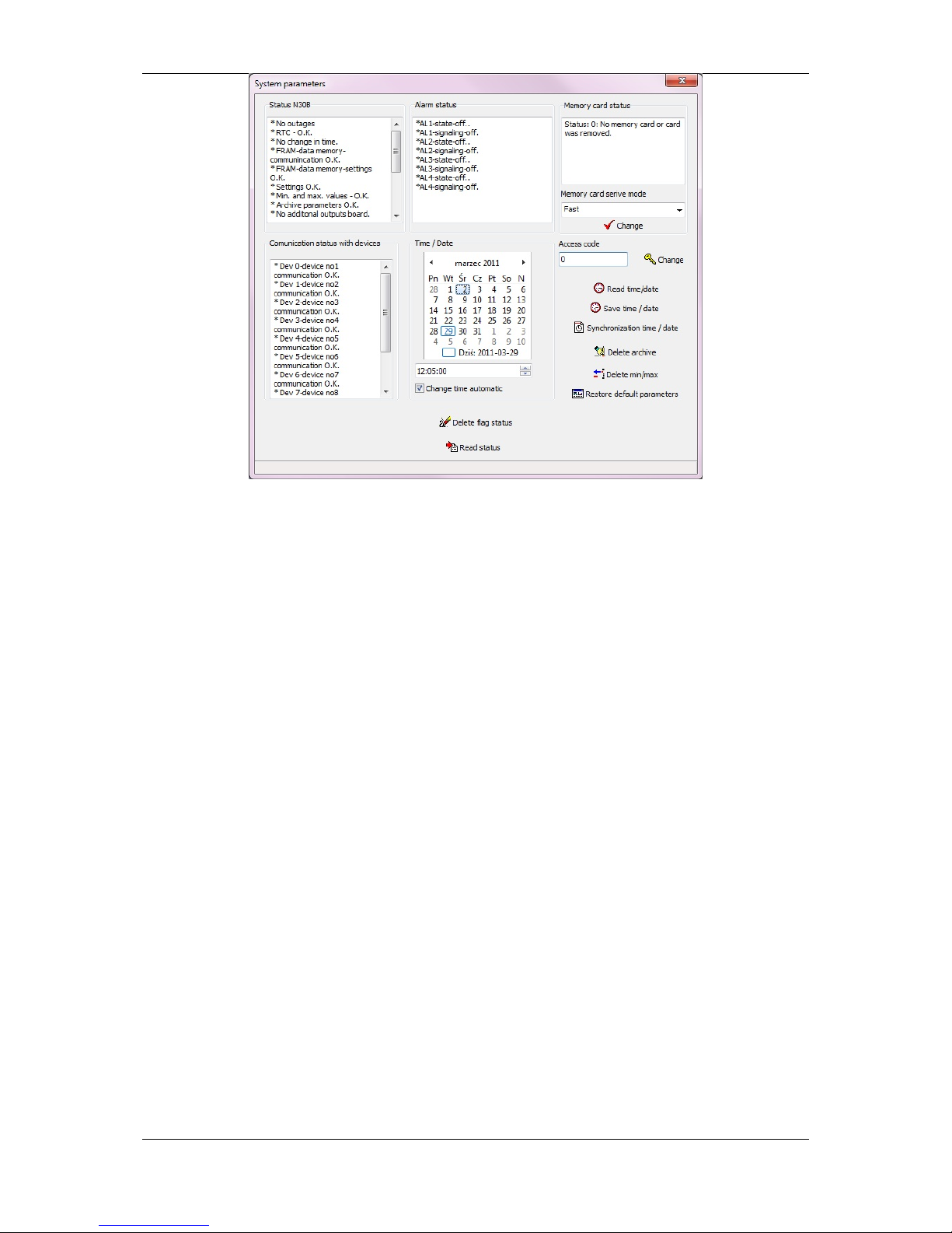
Monitoring of the recorder current state – monitoring of systemic recorder parameters
such as status registers, alarm state, current time and date, memory card state and
state of the communication with added devices (work in the master mode).
Configuration of the recorder time and date with the possibility of the automatic
summer/winter time change.
Change of transmission parameters by means of RS-485 interfaces.
Configuration of archiving and data readout from added devices.
Archive readout from the recorder.
Archive readout from the recorder with the automatic function of archive erasing in the
recorder (after each readout, data will be stored on the disk).
Archive readout from the recorder with the automatic function to erase the archive in
the recorder and locate the read out data in the MySQL® base.
Export of archive files to a format accepted by office softwares.
Export of archive files to the MySQL® data base.
Connection configuration with the data base.
Automatic creation of a table in the MySQL® data base destined to the data
accumulation from N30B recorders ( in the configuration window MySQL®,
section 3.2.5.)
Import of files located in the memory card to the MySQL® data base.
Automatic archive downloading from N30B recorders (service up to 32 tasks). For
each task , the device address is definite individually, what gives the possibility to the
archive readout from many N30B recorders.
Optional configuration of the automatic archive readout from N30B recorders.

N30BProgramminguser’smanual
Page4from33
Global switching of periodical tasks on/off.
Monitoring of current measured values, alarm states, transmission states, etc. on one
software panel together with the visualization of their changes in time.
Graphical archive analysis with the possibility to choice the data source: files or data
base. The user can create a report (maximally 10 diagrams) for any optional
number of N30B recorders. During the creation, one can use the available dictionary
function and see values located in the file or in the data base related to the given
series.
3SERVICE
The N30B software possesses an intuitive user’s interface. Prompts have been implemented
in the software, which appear after directing the mouse index on the given panel element.
The view of the main software window is presented on the fig. 1.
Selectionofthe
portwhichthe
N30Brecorderis
connectedto.
Addressofthe
N30Brecorder.One
mustgivethesame
addressvalue
whichhasbeenset
intherecorder.
Datatransmission
rate.Itmustbethe
sameratewhichthe
recorderhasbeen
configuredon.
Frametype.Itmust
bethesamewhich
therecorderhas
beenconfiguredon.

N30BProgramminguser’smanual
Page5from33
Fig. 1 Main software window
For a correct work, the user must configure connection parameters with the recorder through:
Selection of the serial port which the N30B recorder has been connected to.
Giving the N30B recorder address. One must give the value which has been
programmed in the recorder on (the manufacturer’s address has the value 1).
Selection of the transmission frame type. One must select the same frame type which
the recorder has been configured on (as RTU 8N2 by the manufacturer).
Selection of the transmission rate. One must select the rate consistent with the
current recorder configuration (set as 9600 bit/s by the manufacturer).
Notice: In case of a recorder version without the port 2, it is necessary to set the
recorder on the SLv or SLvA working mode. In the version with the port 2, there is no
need to change the working mode, since the port 2 interface always works in the slave
mode.
3.1 RecorderConfiguration
3.1.1 DisplayandWorkingMode
Notice! : One must remember during the mode configuration, that for the recorder
without the port 2, its switching into the master work mode will cause a lack of
communication with the recorder – it will be necessary to transpose the working mode in
the recorder menu.
For this reason, the working mode change must be carry out in the end of the recorder
configuration. The configuration of display parameters is made after selecting the option
Display/Working mode. After selecting this option, the dialogue window presented on the fig. 2
appears.
Selecttherecorder
registerwhichthevalue
willbedis
p
la
y
ed
Averagingtimeofthe
displayedvalue.
Displayformat
–
number
ofplacesaftercomma.
Recorderworkin
g
mode.
Switchthebacklightofthe
unitplacedontherecorder
dl
dff
Upperdisplayedvalue.
Overflowofthisvalue
causesthedisplayof
theu
pp
eroverflow
Values ofthecolor
change thresholds.
Lowerdisplayvalue.For
valuessmallerthanthis
value,thesymbolofthe
displayedvaluewillbe
displayed.

N30BProgramminguser’smanual
Page6from33
Fig. 2 Display/ Working mode
Additionally, there are push-buttons on the dialog window enabling the readout and the
configuration record. The change of display colours is carried out through clicking on the
selected interval, what causes the change of colours. One must in this way, set required
colours, colour change thresholds and overflow of the displayed value.
After finishing the configuration by means of the configuration record push-button, on can
make the configuration record in the N30B recorder.
3.1.2 IndividualCharacteristic
The individual characteristic enables the user to rescale values of the input quantity. In order
to rescale the quantity before its display and placement in recorder registers, one must
configure parameters of the individual characteristic. The configuration consists of giving the
number of points (number of segments) which will serve to realize the rescaling function.
Then, one must define characteristic points (X) and assign for them values corresponding to
given points (Y).
The configuration of the individual characteristic is performed after selecting the option
individual characteristic. The view of the configuration window is presented on the fig. 3.
Fig. 3 Individual characteristic.
Switchesthe
individual
characteristic
onoroff
Definitionof
thenumberof
characteristic
points
Monitoringof
the
characteristic
operation

N30BProgramminguser’smanual
Page7from33
After finishing the configuration, one must record the characteristic in the recorder. One must
remember, that the change of the displayed value can cause the change of alarm operation
and the analog output if they have been configured for the operation on the displayed value.
3.1.3 AnalogOutput
The configuration of the analog output is made after the selection of the Analog Output.
In order to configure the analog output, one must define the quantity steering the output,
choose the output type and define for which value of the steering quantity, the signal on the
analog output has to accept the value 0%, and for which it has to accept the value 100%.
Additionally, a diagram presenting the operation of the analog output is situated on the panel.
The axis X of the diagram is the steering quantity, however the axis Y is the value on the
analog output
Fig. 4 Analog output
3.1.4 Alarms
The configuration of alarms is realized in the dialogue window started after choosing the
Alarm option. The dialogue window is divided into 4 parts. Each of the part includes
parameters destined for the configuration of the specific alarm. The view of the window is
presented on the fig. 5.
Quantity
steering the
analogue
output
Type of
analogue
output
Value of the
steering
quantity
for which the
signal
reaches
the value 0%
on the output
Value of the steering
quantity for which the signal
reaches the value 100% on
the output

N30BProgramminguser’smanual
Page8from33
Fig. 5 Alarms
During the alarm configuration, one must determine:
▪the quantity steering the alarm. As the steering quantity, one can choose one of the
read out/recorded register by means of the recorder interface, the displayed value or
the clock.
▪Alarm type – defines the way of alarm operation. The operation of particular types of
alarms is presented below:
n-on
n-off
Alarm
output
Output
disabled
Output
enabled
Steeringvalue
Alarm
output
Output
enabled
Output
disabled
Steeringvalue

N30BProgramminguser’smanual
Page9from33
on
off
Lower threshold of the alarm PrL state change.
Upper threshold of the alarm PrH state change.
Delay of the alarm operation expressed in seconds. This value defines the laps of the
alarm state time after which the alarm will be switched over.
Alarm memory – The option switching on causes, that after the alarm start, the diode
on the display remains lighted, signalling in this way the alarm operation.
The alarm memory can be erased by means of recorder push-buttons.
3.1.5 SystemicParameters.TimeandDate
The dialogue window Systemic parameters includes information about the current state of
the N30B recorder. By means of this window, the user can erase status flags and perform
the readout, record operations or the synchronizing of the real time clock. The view of the
dialog window is presented on the fig. 6.
Additionally, one can protect the recorder by a password from the dialog window level. Then,
the entry into the menu from the keyboard level will require giving the access code. The user
has also the option to restore manufacturer’s settings, erase the archive contents and erase
maximum and minimum values.
Notice! : If in the moment of erasing minimum and maximum values, the value to
display is the value signalling an error (e.g. 1E+20), then the erasing operation of
minimum and maximum will not be performed.
SteeringvalueSteeringvalue
Output
disabled
Output
disabled
Output
disabled
Output
enabled
Output
enabled
Output
enabled

N30BProgramminguser’smanual
Page10from33
Fig. 6 Systemic parameters.
The Synchronize time/date option available on the panel causes the synchronization of the
N30B recorder time with the computer time. During the synchronization of the time, the
software waits for the change of minutes on the computer and in the moment, when the
value of seconds in the systemic computer clock has the value 0, makes the record of time in
the recorder. During the use of the record time/date option or read out time/date the value of
seconds is always established on zero.
3.1.6 Connectionparameters
The change of transmission parameters on ports of the serial RS-485 data transmission is
realized by using the Connection parameter window. The window is divided into two groups.
A physical recorder interface corresponds to each group
Port 2 interface – it is the interface located on the additional output plate. This
interface always works in the slave mode. Parameters related to this interface are:
address (in the option without an extra interface in case of operation in slave mode it
always defines the N30B recorder address in the MODBUS network), transmission
mode (type of data frame), transmission rate.
Port 1 interface – it is the interface located on the basic recorder plate. This interface
can operate as master or as slave ( in the version without the port 2). Parameters
which characterizes this interface are: address (only for the operation in the slave
mode), time Out (waiting time for the response from the slavedevice, parameter
expressed in milliseconds), transmission mode (type of data frame), transmission
rate.
The change of interface transmission parameters and their recording in the recorder causes,
that after the change, the software automatically switches over again on newly recorded
parameters.

N30BProgramminguser’smanual
Page11from33
3.1.7 ConfigurationofReadoutandArchiving
The configuration of readout and archiving parameters is available after choosing the option
Readout configuration from devices/archiving. The user can configure the data readout from
added devices (operation in the slave mode) and perform archiving parameters in the
dialogue window .
Fig. 7. Readout configuration from devices/archiving
The configuration of data readout from the device consists of selecting the device
DEV0…DEV9 and next, defining readout and archiving parameters. During the operation in
slave mode, the archiving of recorded registers is assigned to devices. The first 10 registers
correspond to the device DEV0, successive 10 registers correspond to the device DEV1, etc.
During the readout/archiving configuration, one must define following parameters:
Address – defines the address of the co-operating device, the write of the value 0
causes the data readout switch off from the device. This parameter concerns the
recorder operation in master mode.
Basic register – defines the register in the added device which the data readout has
to be followed from – it is the first read out register.
Number of registers – number of read out registers from the device. In case of float
type data composed of two 16-bit registers, one must give as the number of registers,
the number of variables what we want read out from the device (e.g. we read out the
temperature and humidity values from the device, and as the number of registers give
the value 2, despite that these variables occupies four 16-bit registers in the device –
two 32-bit values of float type ).
Register type – defines the register type in the device which data will be read out
from.

N30BProgramminguser’smanual
Page12from33
Pooling period – time expressed in seconds defining the frequency of transmitted
queries to the device. In case of co-operation with devices with a long waiting time for
the response, the time between successive queries can be longer than the time
programmed by the user.
Archived registers – group in which the user sets, which registers among read out
registers have to be archived.
Archiving period – defines the time interval in which read out data will be located in
the archive. Data are located in the archive if there are no communication errors with
the device which data have to be archived from. The archiving period is expressed in
seconds and must be a multiple of the number 10 (minimal archiving period). In case
when giving a number which is not a multiple of 10, the software automatically
matches the archiving period through the execution of the dividing operation on
integers by 10 and rejection the remainder of the division.
Kind of archiving – defines the kind of archiving, Where the user can choose the
continuous archiving with the set archiving period or conditional archiving with the
definition of the register read out from the device. During the conditional archiving, the
value in the indicated register starts or stops the archiving. For the conditional
archiving the condition to archive is the variable “output” in the register steering the
archiving beyond the interval definite by the lower and upper threshold. The overflow
of threshold values causes the archiving start, where registers definite in the group of
archived registers will be archived. The archiving will be carried out then, with an
archiving period given by the user during the configuration.
Lower threshold, upper threshold – define threshold values for the conditional
archiving. If the value steering the conditional archiving is not situated in the interval
defined by these thresholds , the archiving start follows.
3.1.8 Monitor
The window monitoring the operation of the N30B recorder state is available after selecting
the Monitor-readout data option. Thanks to this window, the user can monitor read out
values from devices added to the N30B recorder, the state of the communication with co-
operating devices (including the error statistics) , state of alarms, level of the archive
memory filling, analog output steering, displayed value, minimum and maximum values.
Additionally, there are courses presenting changes in time of the displayed value on the
window, and changes in time of alarm levels. The view of the monitor panel is presented on
the fig. 8.

N30BProgramminguser’smanual
Page13from33
Fig. 8 Monitor
Presented runs can be expanded. The expansion is realized through the marking of the
fragment to be expanded from the left top corner of the given diagram fragment towards the
right top corner, which has to be viewed on the diagram. The withdraw of the marking is
carried out by the marking in reversal direction (from the right top corner towards the left top
corner), although the marked area is of no importance here.
Additionally, a Show read out values push-button is located on the window. After its
pressure, the window presented on the fig. 9 is displayed, including a table with a set of read
out values.
Fig. 9. Read out values
Readoutvalues

N30BProgramminguser’smanual
Page14from33
Descriptions situated in the table have following meanings:
DEV0…DEV9 – devices which data are read out from.
R0…R9 – data read out (registers). R0 means the first read out register from the
device, R1 means the second read out register, etc.
3.1.9 ReadoutandRecordoftheWholeConfigurationfrom/totheRecorder
The readout or record of the whole N30B recorder configuration is possible directly from the
main application panel. One must remember, that during the configuration recording to the
recorder, all configuration data together with the archive configuration and configuration of
transmission parameters are recorded.
Notice!: The configuration recording causes the erasing of the archive located in the
internal recorder memory and the change of recorder transmission parameters.
3.1.10 ReadoutandConfigurationRecordingfrom/totheFile
The configuration of the N30B recorder can be stored in the file and thanks to that, it is
possible to create a copy of the current configuration or duplicate it on other recorders.
Configuration files created earlier can be read in the software, thanks to that, one can modify
them, transmit the read in configuration to the recorder, etc.
During its closing, the N30Bsoftware records automatically the last configuration. However
during the start it reads in the last configuration. The automatic configuration
recording/readout concerns all recorder parameters, and also parameters related to
periodical tasks and the configuration of diagrams.
The configuration of connection parameters with the recorder as: transmission port, address,
and rate will be automatically stored in during the software closing. These settings will be
automatically read in during the software start. Thanks to that, thanks to that, there is no
need to change connection parameters after each software start.
3.1.11 CreatetheMonthlyArchive
If the memory card is used data from pooled devices are stored in daily files. For an Easier
further analysis, one must create monthly archives for individual devices in separate files.
After choosing the option Create the monthly archive, one must indicate the catalogue with
daily files ( on the card or another support with data), the incoming place and press the
Create a new archive push-button.
Files named N30B rrrrmm_Dx.DAT where rrrr – archive year, mm – archive month, x device
number. Exemplary file name: NA30Bo9110002_201101_DO.DAT.
3.2 ServiceofInternalArchive
Archive, data memory of the N30B recorder can be stored in the internal memory enabling to
accumulate 350064 records or in the external memory in the shape of a memory card
located in the recorder socket. The access through the interface is only possible to the
internal memory. The memory card is not available through the interface.
During the archive memory card use as the memory, data can be monitored or exported to
the data base with the use of available import functions of data files in the software. Methods
and available ways to import and data storage are presented in further parts of this manual.

N30BProgramminguser’smanual
Page15from33
3.2.1 ArchiveReadoutthroughtheInterface
The archive readout through the interface is available from the dialogue window level started
from the main panel – Archive-Readout/Conversion option. The view of the archive dialogue
window is presented on the fig. 10.
Fig. 10. Archive
One can divide into two parts the presented window on the fig. 10.
▪Service of functions related to the readout, erasing, and automatic location of data in
the data base.
▪Service of data import and export.
In frames of the first group, the user has the access to following functions:
Archive download – The push-button pressure causes the readout of archived data
from the N30B recorder. Depending on the number of data and connection rate, this
can take a dozen or more minutes. After finishing the data readout, data are located
in the computer memory and can be exported (see the state bar: data in memory).
Additionally in an automatic way, the Archives catalogue is created on the computer
disk, in which the file with lately read out data is located (binary file with the name
corresponding to the date and readout time and including information about the N30B
address which these data arise ) from. One can convert this catalog in the future:
open, review on a diagram or in the table form. After finishing the readout operation it
will be displayed.
Following parameters are related with the readout operation:
Erase the archive after downloading – the marking of the option causes, that after the
archive downloading, data of the N30B recorder will be erased. This option allows to

N30BProgramminguser’smanual
Page16from33
maintain data in order – during the successive readout, only new records will be
downloaded.
Duplicating data will not occur.
Erase the archive after downloading and locate data in the MySQL data base – the
selection of this option causes, that after downloading data from the N30B archive,
archive data will be erased from the N30B recorder memory, and readout data will be
located In the data base. The use of this option requires a correct connection
configuration with the MySQL data base. If during the data readout this option has not
been marked, data can be at once transmitted to the data base by pressing the
Export to data base push-button.
Erase the archive – the selection of the option occasions the erasing of the archive
contents located in the internal recorder memory.
In the second group of functions located on the panel, the user has at his disposal functions
related to data import and export. One can number to these functions:
Export of data readout from the selected time interval to the text file or to the data
base.
Export of data from the definite binary file to the text file or to the data base.
A detailed explanation of functions has been presented below:
3.2.2 ArchiveExporttotheFile
The export of the archive to the file is carried out after selecting the option Archive-
Readout/conversion available from the level of the main application window – group of data
export.
Archive data currently read out from the recorder (data in the software memory) can be
directly exported to the text file after choosing the Export data to the file option. One can
additionally define export parameters such as the date of the beginning and end. In case
when the export beginning date is the same as the export end data, the user can define the
beginning hour and the end hour. Exported data will include the indicated period. After
carrying out the archive readout through the interface, start and stop parameters will be
automatically set on the archive beginning and end.
In order to convert binary files (e.g. coming from the data readout from the recorder operating
on the object or coming from earlier archive readout), one must press the Open archive file
(*.bin) push-button and next indicate the file which has to be read in.
After reading in data on the window status bar, the path and the file name will be displayed,
fields of the first record and last record will indicate the time interval of data located in the file.
Start and stop export parameters defining the time interval for export will be set in the
automatic way. In order to carry out the export to the text file, one must select the Export
data to the file option.
After indicating the file name, the file with text data located in the form of columns separated
by the tabulator index will be created. The format of the text file created by the software is in
compliance with the text stored in the memory card located in the N30B recorder.

N30BProgramminguser’smanual
Page17from33
3.2.3 ArchiveExporttotheDatabase
The archive export to the data base can be carried out directly after the data readout from
the N30B recorder or can be carried out on the base of data coming from earlier archive data
readouts located in binary files. Data export functions to the data base are available in the
dialogue window which appears after pressing the Archive-Readout/Conversion push-button.
The way of the binary file reading in and the selection of the data time interval is presented in
the section Export Archive to the File. In case of data export to the data base, one must
proceed in the similar way, and after defining export parameters, one must press the Export
data to the data base push-button.
The direct data export to the data base after the archive readout by the interface is possible if
before the archive download, the Erase the archive after download and locate data in the
MySQL data base option will be marked or after downloading through the pressure of the
Export data to the data base push-button.
Notice: One must remember, that the data export to the MySQL data base can follows only
in case, when the connection with the data base has been correctly configured - MySQL-
connection configuration dialogue window.
3.2.4 ConversionofTextFilestotheDatabase,ConnectionConfiguration
Text files being the result of data export or coming from the memory card on which the N30B
recorder archived data, can be located in the data base. In order to locate data from text files
(*.dat), one must transit to the MySQL dialogue window. To this aim, one must press the
MySQL- connection configuration push-button. Then, the dialogue window presented on the
fig. 11 will be displayed.
Fig. 11. MySQL.

N30BProgramminguser’smanual
Page18from33
Before beginning to the text file conversion and locating data In the data base, one must
configure the connection with the data base. For this aim, one must give:
Server – IP address or the server name on which there is the MySQL data base. In
case, when it is the base located in the same computer on which the software has
been started, it is enough to give local host as the name or give the address:
IP 127.0.0.1
Port – port on which the MySQL server listens out. The standard configuration
operates on the port 3306.
Data base – data base name. The data base must exist in the server.
Table – table name which exists or will has to be created.
User – user’s name possessing entitlements to add data to the table definite in data
configuration (INSERT) and to review data from the base (SELECT).
Notice: in case, when the table will be generated from the level of the N30B software,
the user must have entitlements to the data base allowing to create the table.
Password – password for the user authorizing to access to the data base.
Transmission compression – makes possible the compression switching on during
the connection with the data base.
After giving connection parameters, one can create a table in which data will be stored or
make a connection test with the data base.
In case, when in the data base there is no table given in the table field, the data import from
the text file does not succeed.
The import of the text file consist of giving the recorder address which data are coming from
( the address is a parameter which serves to differentiate recorders located in one table and
it is not recorded in the file), and next, one must click the Indicate the file to be imported
push-button. After indicating the file the data import process and location them in the data
base will begin. After finishing the process, the number of added records to the data base will
be displayed on the panel.
3.2.5 AutomaticArchiveDownloading
The automatic archive downloading allows to defining 32 tasks, what allows to download
data in various hours, in various days. Thanks to automatic tasks, one can download data
from 32 N30B recorders once a day. The operation of automatic data download has a sense
only for N30B recorders accumulating data in the internal memory
Automatic tasks are started 60 sec. after the software starting. If there are overdue tasks
from the given day, they will be carried out.
The configuration of automatic tasks is carried out in the Automatic archive download
dialogue window presented on the fig. 12

N30BProgramminguser’smanual
Page19from33
Fig. 12 Automatic archive downloading
The addition of new tasks consists of pressing the Add task push-button. Next, in the new
added task, one must give following parameters:
Task name – any text.
N30B address – recorder address from which data will be read out.
Time of the task beginning - defines the time since which the task should begin. If
more tasks will be defined in the same time, they will be set in a queue and next
cyclically performed.
Day of the task beginning – defines the weekday in which the task will be carried out.
Repeat the task – defines when the task has to be repeated. Selecting the lack of
repetition option causes, that the after carrying out the task will be erased from the
list.
Locate data in the data base – the marking of this option causes, that after carrying
out the task, data will be automatically located in the data base. In case when this
option is switched off only binary files are created in the Archives catalogue.
After defining the task, one must press the Apply push-button in order to actualize the task.
Note: during carrying out periodic tasks the software can no answer. The fact to realize
periodic tasks is signaled by the software through the software icon display in the systemic
bar (by the clock in the task bar).
Additionally, the user can stop the execution of systemic tasks, and next start them manually.
All messages of the automatic task module are displayed in the dialogue window allowing the
operation checking, communication correctness and the state of periodic task realization.

N30BProgramminguser’smanual
Page20from33
3.2.6 AnalysisofArchiveDataGraph
Accumulated archive data can be reviewed on the graph dialogue window. The user can
review any data in the shape of graphs. Created graphs can be printed. Moreover, there is
the possibility to review data in the shape of a table. The view of the dialogue window Graph
is presented on the fig. 13. The meaning of edition fields and push-buttons located in the
dialogue window is presented on the fig. 14. One must remember to press the Apply push-
button after each parameter change of the given series, what causes the data download
about the series.
The series configuration is automatically recorded during the software closing and is read in
after starting the software. Thanks to that, the generation of such same graphs from different
periods does not require a continuous configuration of series parameters.
Fig. 13 Diagram
The lateral panel of dialogue window (fig. 14.) includes push-buttons, text fields and selection
fields. Functions fulfilled by these fields are as follow:
Clear the graph – The push-button pressure causes the clearing of all graphs and the
data erasing from tables. Series connections will be preserved.
Erase series connections – The push-button pressure causes the erasing of all series
and clearing of the graph. The series configuration will be erased.
Data from – date defining the period beginning. Selection fields of the date are
destined to define the time interval from which the graph interests us.
Data to – data określająca koniec wykresu.
Series selection – the field serves to select the series, the configuration of which we
want to change. After introducing the change, one must press the Apply push-button.
Table of contents
Other Lumel Recording Equipment manuals