manuals.online logo
Brands
  1. Home
  2. •
  3. Brands
  4. •
  5. LumenRadio
  6. •
  7. Lighting Equipment
  8. •
  9. LumenRadio W-Modbus User manual

LumenRadio W-Modbus User manual

24V
AC/DC A+ B-
GND
POWER CONNECTION AND MODBUS CONNECTION
The W-Modbus units have 24 VAC/VDC power in/out connection and con-
nection for Modbus communication.
INSTALLATION
1. Conrm that the W-Modbus unit has no visible damage
2. Install the W-Modbus unit close to the Client/Server it should be con-
nected to
3. The W-Modbus enclosure is wall mounted and ts onto a junction
box. Start with mounting the back piece of the enclosure.
4. Connect the power supply and Modbus Client/Server to the W-Mod-
bus unit, as shown to the right. Use the rear and/or top knockouts for
cable entry. All W-Modbus units are factory set for Node operation
without the need for additional conguration when connected to a
Modbus Server.
5. Fit the front piece to the back piece
6. Check that the W-Modbus unit and its wiring are securely mounted
(ifthe unit is powered this will be indicated by the LEDs)
W-Modbus is an end device with internal termination resistor.
APPLICATION AREA
The W-Modbus product transmits Modbus RTUsignals wirelessly. It is
designed to be used indoors as a Modbus RTU cable replacement.
GENERAL
All relevant personnel must acquaint themselves with these instructions be-
fore installation. Any damages to the product and its parts due to improper
handling are not subject to warranty if the product not has been handled
according to the outlined instructions. For additional W-Modbus documen-
tation, visit www.lumenradio.com.
WARRANTY
The warranty or service agreement will be deemed void if:
(1) The product is repaired, modied, or changed, unless such repair, modi-
cation or change has been approved by LumenRadio AB; or
(2) The serial number on the product has been made illegible or is missing.
THE PACKAGING CONTAINS
1 x W-Modbus
1 x Instruction leaet
MANUFACTURER
LumenRadio AB
Svangatan 2B
416 68 Gothenburg
Sweden
ELECTRICAL SAFETY
Only qualied electricians or service personnel trained by LumenRadio may
perform interventions in connection with electrical installation. Always fol-
low local/national rules when performing this type of electrical installation.
When connecting a 24 V isolation transformer, this must be done in accor-
dance with IEC 61558-1.
TECHNICAL DATA
Power supply: 24 VAC ±15% 50-60 Hz, 24 VDC ±15%
Max. power consumption: 2.5 W
24 V output max. power: 10 W
Auto resettable fuse: Yes
Cable rating, connector: solid / stranded
0.14 - 0.5 mm2 / 0.2 - 0.5 mm2
conductor sizes (AWG) 24 – 20
by LumenRadio
W-Modbus
www.lumenradio.com
Copyright © LumenRadio AB 2021
All Rights Reserved www.lumenradio.com
Frequency band: 2.45 GHz, ISM band (2400-2483 MHz)
Baud rate: 9600, 19200, 38400, 76800 bps
Number of Servers: 100 Servers to one Client
Number of hops: 8 hops in the meshing network
Range per hop: 500 m line of sight (approximately 50-
70 m indoors with walls)
Output (ERP): Max 20 dBm
IP class: 40
Material: ABS UL94-V0
Colour: White, RAL 9003
Ambient temperature: Operating: -20 to +55°C
Storage: -30 to +80°C
RH: 10 – 95% non-condensing
Weight: 95g
Dimensions: W86.0 x H86.0 x D25.5 mm
SYSTEM OVERVIEW
A W-Modbus network consists of a single W-Modbus Gateway connected
to the Modbus Client using a Modbus RTU cable and up to 100 W-Modbus
Nodes, each of them connected to one Modbus Server over a Modbus
RTU cable.
W-Modbus Gateway
Modbus RTU cable
Wireless Mesh
W-Modbus Node
Client
Server
Server
Server
Server
Server
Server
The W-Modbus network is built on LumenRadio’s MiraMesh, a self-forming
and self-healing wireless mesh technology. For more information about
MiraMesh visit www.lumenradio.com
SCAN ME
MANUAL W-Modbus LUMENRADIO
FCC ID: XRSTIMOMWAN201
IC: 8879A-TIMOMWAN201
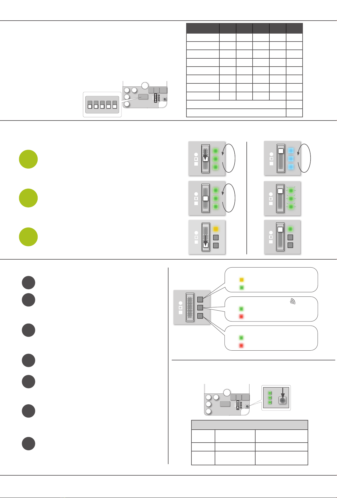
All uncommissioned W-Modbus Nodes will, at power up, start scan-
ning for a W-Modbus Gateway. The LEDs will turn blue color and
ow from top to bottom during this process.
To initiate the W-Modbus Gateway node scan, position the 3 pole
switch in the middle position on the Gateway. During the Gateway
scan process the 3 LEDs will ow from top to bottom in green color.
Wait for all W-Modbus Nodes to nd and connect to the Gateway,
the LEDs on the Nodes will start to ash in green color. This process
can take up to 5 minutes.
When connected, set the switch on the W-Modbus Gateway to the
bottom position. This will restart the W-Modbus network in secure
mode. This is indicated by the top LED, yellow for W-Modbus Ga-
teways and green for W-Modbus Nodes. In this mode the status of
wireless signal strength and Modbus RTU cable connection status
will be indicated by the LEDs as shown under System status.
1
2
3
COMMISSIONING W-MODBUS GATEWAY W-MODBUS NODE
MANUAL W-Modbus LUMENRADIO
Flow
Flow
Flow
Flash
ON
1 2 3 4 5
Set the baud rate, parity and stop bit settings on the W-Modbus Gateway to
match the settings of the Modbus Client.
All W-Modbus Nodes are by default congured to receive their baud rate,
parity, and stop bit from the W-Modbus Gateway in the system. It is possible
to override the individual W-Modbus Node setup, effectively mixing settings
within the network.
After setting Baud Rate, Parity and Stop Bit, each
W-Modbus Node will scan for the connected
Servers Modbus address
(1-255) in sequence, it may
take up to 2 minutes before
the address is found.
1 2 3 4 5
9600 baud OFF OFF - - -
19200 baud OFF ON - - -
38400 baud ON OFF - - -
76800 baud ON ON - - -
No parity - - OFF - -
Even parity - - ON - -
1 stop bit - - - OFF -
2 stop bit - - - ON -
Use local serial conguration set on Node ON
Use Gateway serial conguration on Node OFF
PUSH BUTTON
Push Turn ON LEDs All LEDS turn on
(turns OFF after 30 min)
Hold 10 s Uncommissioning Mid LED indicates blue
Hold 20 s Firmware update
mode*
Mid LED indicated red
PUSH BUTTON
The push button enables the LEDs, uncommissioning and rmware updates.
*Find FW update instructions on www.lumenradio.com
SYSTEM STATUS
Does the unit have power? Press the push button, if the LEDs are
not switched on, check the power connection.
Can the Modbus Client handle the timeout requirements?
Is the unit connected to the network?
Check the Wireless Network status LED. A Node with a owing blue
light is not connected to the network. Reference the commission
section to ensure the unit ashes green before switching the Ga-
teway into secure mode. If the owing blue light persits the range
of the unit might be too far away from the network. Try installing an
extra W-Modbus unit in between.
Is the network within the limits of the maximum (100) units allowed?
If the Wireless Network Status indicates bad wireless network (red
LED) make sure the distance between W-Modbus units are within
the requirements or add an extra W-Modbus unit as a repeater to
get better wireless coverage.
If the Modbus RTU Cable Communication indicates no communi-
cation (red LED) check if the Modbus RTU cable is correctly instal-
led and make sure the Baud rate, Stop bit and Parity settings are
correct.
Have all the Nodes joined during commissioning (all LEDs ashes
green) but not all nodes entered the secure network when the Ga-
teway is set to secure network (yellow LED). Make sure only one unit
is set to Gateway mode during commissioning. It is only possible to
install one network at a time.
?
TROUBLESHOOTING
?
?
?
?
?
*W-Modbus Node ashes green when commissioned and joining the network
?
BAUD RATE, PARITY AND STOP BIT
For more information, FAQ and the latest version of the
W-Modbus Manual visitwww.lumenradio.com.
Gateway/Node Indicator
Gateway
Node*
Wireless Network Status
Good Link
Bad Link
Modbus RTU Cable Communication
Good Connection
No Connection
Copyright © LumenRadio AB 2021 v2.0
All Rights Reserved www.lumenradio.com

Other LumenRadio Lighting Equipment manuals

LumenRadio CRMX Stardust User manual

LumenRadio

LumenRadio CRMX Stardust User manual

LumenRadio CRMX Luna User manual

LumenRadio

LumenRadio CRMX Luna User manual

LumenRadio MoonLite User manual

LumenRadio

LumenRadio MoonLite User manual

LumenRadio W-DALI User manual

LumenRadio

LumenRadio W-DALI User manual

LumenRadio Exalux CONNECT RX100 User manual

LumenRadio

LumenRadio Exalux CONNECT RX100 User manual

Popular Lighting Equipment manuals by other brands

Vision & Control DL30x30-W5K7/UDC/-a Instructions for use

Vision & Control

Vision & Control DL30x30-W5K7/UDC/-a Instructions for use

VELAMP PS066 manual

VELAMP

VELAMP PS066 manual

Laura Ashley Aidan Installation & operation guide

Laura Ashley

Laura Ashley Aidan Installation & operation guide

Miledo BAREV R quick start guide

Miledo

Miledo BAREV R quick start guide

JONATHAN Y JYL5041A instructions

JONATHAN Y

JONATHAN Y JYL5041A instructions

ML Accessories Knightsbridge BT9H4/6K Installation & maintenance manual

ML Accessories

ML Accessories Knightsbridge BT9H4/6K Installation & maintenance manual

Robin Robin 300 plasma spot user manual

Robin

Robin Robin 300 plasma spot user manual

JB Systems DynaSpot Operation manual

JB Systems

JB Systems DynaSpot Operation manual

babymoov Veilleuse Tweesty Instructions for use

babymoov

babymoov Veilleuse Tweesty Instructions for use

Good Earth Lighting RE1250-BKG-12LF1-G Easy installation

Good Earth Lighting

Good Earth Lighting RE1250-BKG-12LF1-G Easy installation

weltico EASYLED IKONE manual

weltico

weltico EASYLED IKONE manual

Classy Caps SL994 quick start guide

Classy Caps

Classy Caps SL994 quick start guide

Rush DC 1 Aqua user manual

Rush

Rush DC 1 Aqua user manual

Angler COL-1212 Instruction

Angler

Angler COL-1212 Instruction

Silverline 365874 manual

Silverline

Silverline 365874 manual

AC SD32PHL user guide

AC

AC SD32PHL user guide

Allmand MAXI LITE ML FCS Series Operator's manual

Allmand

Allmand MAXI LITE ML FCS Series Operator's manual

KAM Star Cluster Micro RB 300 instruction manual

KAM

KAM Star Cluster Micro RB 300 instruction manual

manuals.online logo
manuals.online logoBrands
  • About & Mission
  • Contact us
  • Privacy Policy
  • Terms and Conditions

Copyright 2025 Manuals.Online. All Rights Reserved.