Luminex LumiNode Series User manual

USER MANUAL
LUMINODE PRODUCT FAMILY
LumiNode 1 / LumiNode 2 / LumiNode 4 / LumiNode 12
THANKS FOR CHOOSING LUMINEX
Description: User Manual for the complete LumiNode series.
REVISION: 20200618-REV 2.2.1

2

TABLE OF CONTENTS
1. INSTALLATION.................................................................... 4
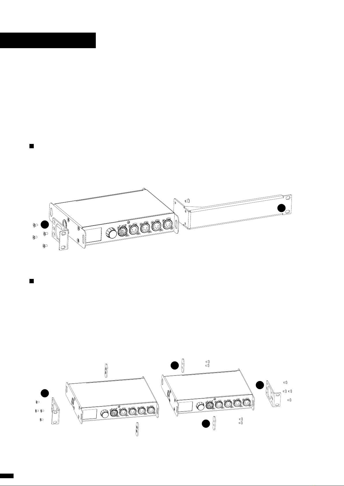
1.1 Mounting the device........................................... 4
Rack mount...................................................................................4
Rack mount - two devices...................................................4
Truss Mount – LumiNode 4.................................................5
Truss Mount – LumiNode 2.................................................6
Wall Mount – LumiNode 2 ..................................................6
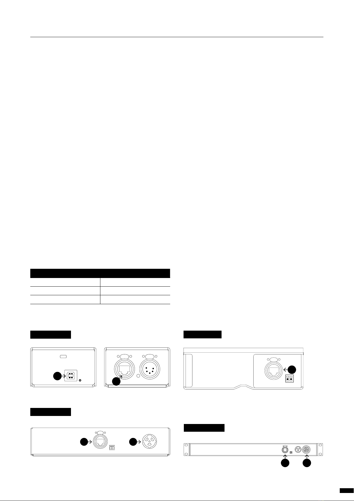
1.2 Power up the device............................................ 7
1.3 Connection............................................................ 8
Connection to the network................................................8
Connection to the USB port...............................................8
1.4 LED indicators....................................................... 8
1.5 Connection to the web interface ...................... 8
1.6 Reset 8
2. CONFIGURATION ............................................................... 9
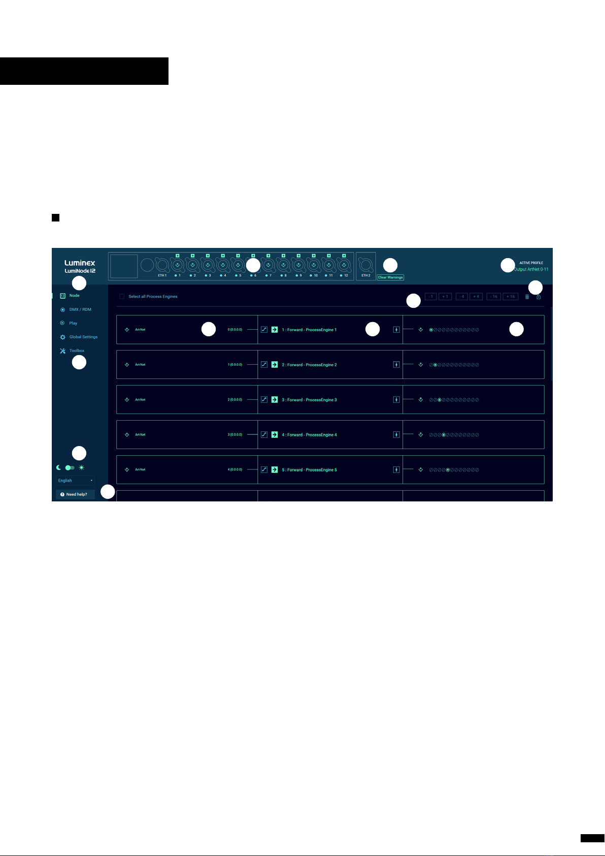
2.1 Web Interface Presentation ............................... 9
Node page.....................................................................................9
How to reset a process engine......................................10
How to configure a Process engine............................10
DMX / RDM page ...................................................................11
Port Settings..............................................................11
DMX Settings............................................................11
DMX Redundancy..................................................12
Play page.....................................................................................13
Show..............................................................................13
Record Trigger.......................................................... 13
Toolbox page............................................................................ 14
Profile Manager ....................................................... 14
Firmware...................................................................... 15
Reset...............................................................................15
3. GLOBAL SETTINGS ..........................................................16
Control Source.........................................................16
IP Settings ...................................................................16
Device Settings........................................................16
Contact Closure.......................................................16
Miscellaneous...........................................................17
4. LCD DISPLAY ...................................................................18
5. WEB API ............................................................................20
6. LumiNode IN DETAIL.......................................................21
6.1 What is a Process engine? ................................21
INPUT .............................................................................................22
DMX................................................................................ 22
ArtNet............................................................................ 22
sACN...............................................................................22
RTTrPL............................................................................22
Internal..........................................................................23
Play.................................................................................. 23
OUTPUT........................................................................................23
DMX................................................................................ 23
ArtNet............................................................................ 23
sACN...............................................................................23
Mode definition.......................................................................24
FORWARD ...................................................................................24
LTP MERGE..................................................................................24
HTP MERGE.................................................................................24
BACKUP.........................................................................................24
X-FADE...........................................................................................24
SWITCH .........................................................................................25
CUSTOM.......................................................................................25
PATCH OPTION.........................................................................26
MASTER OPTION .....................................................................26
Master / Limit explained....................................27
7. CREDITS ...................................................................27
3

1.INSTALLATION
1.1 Mounting the device
Depending on the model of the device there are different mount-
ing options:
LumiNode 4 is a device that can be mounted in a truss as well as
in a rack. Please read the following instructions to make sure the
device is mounted and secured correctly.
RACK MOUNT LumiNode 4
In case you want to mount your LumiNode 4 in a standard 19-inch
rack, you must attach the included mounting ears. Connect the
longest ear (A) to the right-hand side of the device with 4 screws,
re-used from the device. Attach the shorter ear (B) to the left-hand
side again with the 4 screws.
RACK MOUNT TWO DEVICES
In case you want to mount two LumiNode 4 devices or a Lumi-
Node 4 and a LumiCore in a standard 19-inch rack you can mount
the two devices together. A space saving way as the two devices
will only consume a single row in your 19-inch rack.
First you attach the shortest mounting ears. Connect the short-
est ear (C) to the left-hand side of the first device with 4 screws,
re-used from the device. Attach the other shortest ear (D),
delivered with the second device, to the right-hand side of the
second device, again with 4 screws. Use a pair of mounting brack-
ets (E) to connect the two devices in the middle on the frontside.
Use a second pair of mounting brackets (E), delivered with the sec-
ond device, to connect the devices at the rear. Each pair of brack-
ets musts be mounted with 2 screws.
A
B
A A
B B
C C
D D
E E
F F
G G
H H
12
12
11
11
10
10
9
9
8
8
7
7
6
6
5
5
4
4
3
3
2
2
1
1
C
E
E
D
4

To combine a LumiNode 4 device with a Luminex half 19” device,
style GigaCore 10, the mounting procedure differs a little.
The bolt (F), not included, replaces the rear couplers at the rear
side of the device. Use the correct bold, M10x20, with a screw wire
no longer as 20mm. You can order this part from Luminex (Part
Number: R 90 01042)
Screw the bolt, through the LumiNode 4 back ear, into the side
M10 insert and tighten it. The rest of the mounting procedure re-
mains the same.
TRUSS MOUNT LumiNode 4
To mount a LumiNode 4 in a truss, you must attach a M10 clamp
(G) to the M10 insert (H). After that, you can mount the clamp to
the truss bars. Please also secure the device by attaching a safety
line directly to the truss bars as well (I).
F
G
I
H
5
1 | INSTALLATION / 1.1 MOUNTING THE DEVICE

TRUSS MOUNT LumiNode 2
To mount a LumiNode 2 in a truss, use the two plastic
tie wraps that are included. Bring on each side a tie
wrap through the holes of the device, around the truss
bar and tighten it (J). Please also secure the device
by attaching a safety line directly to the truss bars as
well (K).
WALL MOUNT LumiNode 2
The LumiNode 2 can be mounted to a concrete or wood wall by
using applicable screws and anchors. Make sure that the screw
head diameter is between 8 – 10mm and the screw length is at
least 40mm in order to make a strong wall connection.
Ø 8-10mm
≥ 40mm
Drill 4 holes, at the correct distance in both directions as indicated
in the picture below. Mount the device in such way that the Eth-
ernet and DMX ports are facing sideways, and the chassis side is
perpendicular to the ground.
J
K
139mm
112mm
L
6
1 | INSTALLATION / 1.1 MOUNTING THE DEVICE

1.2 Power up the device
Depending on the model there are different ways to power your
device:
LumiNode1: Power-up the device with a USB cable (U) or with
PoE (N). The device will automatically switch on. To shut it down
after use, just un-plug the USB cable or the network cable again.
LumiNode2: Power-up the device with a network cable with PoE
(N). The device will automatically switch on. To shut it down after
use, just un-plug the network cable again.
LumiNode4 and 12: Power-up the device with a power cable fitted
with a Neutrik PowerCONTRUE1 connector (M) (please contact your
local dealer if you do not have a suitable power cable at hand). The
device will automatically switch on. To shut it down after use, just
un-plug the power cable again. LumiNode4 and 12 can also be
powered with PoE (N).
The LumiNode 4 and 12 require standard AC power distribution from
100-240VAC, 50/60Hz. Current required depends on the model.
The mating Neutrik® powerCON® TRUE1 connector is supplied; how-
ever, you will need to purchase or construct a cable appropriate for
your application.
When installing a new connector please refer to the following wire
colour code reference:
WIRE* CONNECTION
Green/Yellow AC Ground
Blue AC Neutral
Brown AC Line
* International (Harmonised) Standard
Alternatively, the LumiNode series are 802.3af compliant (PoE), so
that each LumiNode will act as a PD (Powered Device) and can be
powered by any compliant PSE (Power Sourcing Equipment) such
as Ethernet switch, midspan and PoE injector. All models can only
be powered with PoE via Eth2!
For LumiNode 4 and 12, if both AC power and PoE are used the AC
power supply will be prioritized but the PoE will seamlessly take
over if the AC power fails.
The LumiNode12 offers the option to daisy chain up to 30 devices
via the PowerCON TRUE1 outlet on the rear of the unit.
U
N
LUMINODE 1 LUMINODE 2
N
LUMINODE 4
N M
LUMINODE 12
N M
7
1 | INSTALLATION / 1.2 POWER UP THE DEVICE

1.3 Connection
CONNECTION TO THE NETWORK
To get the LumiNode online in your system, connect either the Eth-
ernet 1 or Ethernet 2 port to a computer, or to a port of an Ethernet
switch. Only Ethernet 2 port on the rear of the unit can be used to
power the unit through PoE. Check the port labelling for a better iden-
tification.
CONNECTION TO THE USB PORT
The LumiNode 1 can be powered through its USB port. Connect the
LumiNode to the USB port of your computer.
The red LED next to the USB port of your device will turn on once the
unit is powered. Once the unit has booted up the led will turn blue.
Additionally, the LumiNode will appear as a new network interface on
your computer. No driver needed, the LumiNode supports Windows,
Mac OSX and Linux OS. Once the network adaptor has been added
please configure a static IP address in the range you are planning
to use for your application in the settings of your operating system.
1.4 LED indicators
There are various LEDs on the LumiNode. Here is a list of the LEDs, the
possible colors and the meaning of each color
DMX PORT STATUS MEANING
DMX Input Green Blinking : Active input
DMX only (output
mode)
Cyan Blinking: DMX activity
DMX + RDM (output
mode)
Blue Blinking: DMX activity
Stream loss Red Source stream lost
Stream recovered Orange Source stream recovered
DMX redundancy Magenta
Magenta
flashing
Output idle
Output active
NETWORK PORT
Left LED (Link) Green Gigabit connection
Blinking: Ethernet Traffic
Orange 100Mbit connection
Right LED (Mode) Blue Default color
Green
flashing
Device booting
Orange
blinking
Firmware upgrade in
progress
Green
blinking
Identify in progress
USB PORT
USB (node1 only) Red Powered from USB or PoE
during bootup
Blue Unit booted and running
Orange
blinking
Firmware upgrade in
progress
Green
blinking
Identify in progress
1.5 Connection to the web interface
The LumiNode IP address is displayed at the rear or on the bottom
of the unit. On the LumiNode 4 and 12 this can also be found on
the LCD display. Set your computer with a compliant IP address
(do not use the same IP address!).
Connect your computer to the LumiNode with a network cable.
Launch your favourite web browser.
Type the IP address of the LumiNode in the address field followed
by enter.
1.6 Reset
When the device is powered up, by default it shows the status
screen with the status of the first 4 ports. In order to reset the
device please follow the following steps:
Press the jog wheel once to enter the Main menu.
Scroll down until you see Toolbox.
Press the jog wheel once to enter the toolbox.
Scroll down until you see Reset.
Press the jog wheel once to enter the reset menu.
A pop-up window opens giving you the option to Preserve IP
settings and Preserve user profiles.
Choose which option you want by using the jog wheel to
scroll between the two options and press the jog wheel to
confirm.
At the bottom of the pop-up window you have the option to
Reset or Cancel.
If you choose Cancel you get a message that the reset has
been cancelled.
If you choose Reset, you get a new screen asking to confirm
the reset command. Once‘Yes’is selected the LumiNode will
reset.
How to reset LumiNode through Luminet Monitor:
With a computer connected to the device, open Luminet
Monitor.
Under “Tools”in the menu bar you find “Reset LumiNode”.
Enter the mac address of the device you want to reset. This
can be found on the label with the IP address.
Choose if you want to keep the IP settings.
Choose if you want to keep the profiles.
Click reset.
8
1 | INSTALLATION / 1.3 CONNECTION / 1.4 LED INDICATORS / 1.5 CONNECTION WEB INTERFACE / 1.6 RESET

2.CONFIGURATION
2.1 Web Interface Presentation
Launch your favorite web browser and type the IP address of your
LumiNode. Press enter to validate.
NODE PAGE
C
A
D E F
G
H
JIB
K
L
(A) Identify: Clicking on the Luminex logo will identify your
LumiNode in the network. The LCD display will turn GREEN and the
Mode LED will flash GREEN for 5sec. In the web-UI you get the text
“Identified”under the Logo and the LCD area will change colour.
(B) Image of your LumiNode: Depending on the model you are
using; the image might differ from the one displayed above. This
product image shows the configuration of each DMX port. The
centre icon within each DMX port represents an input or an out-
put. On the top of each port, you can see the mode of the process
engine linked to that port.
(C) Navigation menu
(D) Input: According to the mode set on the process engine, the
input block will display all relevant information, such as the type of
incoming protocol, the universe number, the source IP address, or
the DMX input port.
(E) Process engine: By default, the LumiNode comes with For-
ward mode activated on as many process engines as DMX port(s).
The block displays the mode currently set on the process engine;
you can change the name. On the left and on the right-hand side
of the process engine, are respectively the patch and master /
limiter icons. The colour of the icon will change if any parameters
of these menus are modified. For more details about the process
engines and how to configure them please see chapter 6 of this
manual.
(F) Output: The output block will display all relevant information,
such as the type of outgoing protocol, the universe number, the
destination IP address, or the DMX output port.
(G) Increment / Decrement: Use these shortcuts to quickly in-
crease or decrease the value of a universe. Select the Process en-
gine first, after which the increment / decrement tool becomes
available.
(H) Reset tool and padlock: Use this tool to reset one or several
process engines. First select the process engine(s) by clicking on
the top left corner of the input block followed by the trash can
icon. The padlock allows you to lock the LumiNode configuration
page to prevent unsolicited action on the web page only. This is an
ideal tool for show time.
(I) Clear Warnings: Clear all stream loss indications.
(J) Active Prole: In this area the current active profile of the
LumiNode is being displayed.
(K) Theme and language: Select here if you want to use the dark
theme or light theme. Interface supported languages are English
and Japanese for now.
(L) Help: In case you need help, here you find an onboard helpfile.
9

How to reset a process engine
To reset a process engine, follow the following steps:
Hover your mouse over the top left corner of the process
engine and select the tick box.
Click on the trash can icon at the top right corner above the
first process engine.
A blank process engine appears as follows:
If you want to reset all the process engines at once, navigate to
the top left above the first process engine and select the tick box
“Select all Process Engines”.
How to congure a process engine
To configure a process engine, first click on the “SELECT MODE”
label (the centre block of the process engine), the process engine
panel appears. Click on the icon to select the mode you wish to
use. Modes are described in chapter 5 of this manual.
Forwardan input is sent to an output .
LTP merge, Latest Takes Precedence with up to four
inputs .
HTP merge, Highest Take Precedence with up to four
inputs .
Backup, Input 2 becomes active if input 1 is not available .
X-Fade, Cross-fade between input 1 and input 2 .
Switch, with the use of a control source choose which of the
up to four inputs is+ active .
Custom, any of the other modes, or combination of,
on a channel level .
At any time, you can click on the Patch button , or the Master
/ Limit button to open the relevant configuration panel.
Next, click on the left-hand block, to select your input . Ac-
cording to the selected mode, the number of inputs may vary. A
process engine supports up to four inputs.
Input options are:
DMX: Physical input on the XLRs.
ArtNet: Select the ArtNet universe to use. You can enter a
numeric value between 0 and 32767.
sACN: Select the sACN universe to use. You can enter a
numeric value between 1 and 63999.
RTTrPL, BlackTrax: Select the RTTrPL universe to use. You can
enter a numeric value between 0 and 63999.
Internal, the result of another process engine.
Play, one of the recorded shows.
You can give your input a name for easy identification. Next, select
your output by clicking on the output block, located on the
right-hand side.
Here, you can choose between DMX, ArtNet, sACN or a combina-
tion of the three to send data coming from the process engine.
The three types of output can be used at the same time, providing
you with great flexibility.
Once selected, click on the Save button to store the parameters of
your process engine. Your engine is ready to go!
10
2 | CONFIGURATION / 2.1 WEB INTERFACE PRESENTATION / RESET & CONFIGURE A PROCESS ENGINE

How to quickly copy a process Engine
Once you have created your first process engine, select it by click-
ing on the tick box in the top left corner. A handle appears at the
bottom centre of the process engine.
Click and drag the handle down, to select other process engines.
The LumiCore will automatically increase the universe number for
each following process engine. This allows you to create a com-
plete configuration in a snap!
THE DMX / RDM PAGE
The DMX / RDM page is divided in two sub menus:
Port Settings
The port settings oers you to:
Add a legend to a port to easily identify what is connected to
it. This will also update the tooltip on the configuration page
of the process engine.
Enable Sync mode: when enabled the DMX output framerate
is matched to the input framerate. If the source used for this
port has the ability to send an ArtNet or sACN sync packet this
will be used.
Redundant Slave: when enabled the DMX port listens to
incoming DMX from another port or another node and will
start outputting if NO input is registered. When DMX redun-
dant slave is enabled RDM is automatically disabled.
Enable RDM, enabling RDM allows RDM traffic to be
transported from/to an outlet over the network and back.
• Adaptive discovery. When RDM is enabled it is possible to
enable Adaptive Discovery. This will continuously check
for new and disappeared RDM devices on the output.
• Interweaving. Interweaving is enabled by default. Inter-
weaving is only available when the FPS is set lower or
equal to 34fps. Interweaving makes that RDM messages
are interweaved with DMX. If your fixture does not support
interweaving or the RDM packets you are sending are too
large you would disable RDM interweaving. For example,
with a RDM based follow-spot system interweaving needs
to be disabled.
• ArtRDM universe. The ArtRDM universe is the universe
which is used for ArtTOD and ArtRDM packets. By default,
this will be matched to the ArtNet universe of the first Art-
Net input of your process engine.
Scroll down and click“Save” to save your settings.
At the bottom of the process engine section you can find a button
to force an RDM discovery in case this is required.
DMX Settings
On the DMX / RDM page at the bottom of the page you find the
DMX settings.
DMX Framerate in Frames Per Second
Breaktime in microseconds
DMX output time continuous by default is enabled and the
LumiNode will keep outputting the last received stream
packages on the DMX. When you disable the continuous out
put time you can choose a time the LumiNode will keep
outputting the data with a minimum time of 1 second.
RDM Controller IP is the only device in the network that can
make changes via RDM. When 0.0.0.0 every device in the
network can make changes but if you want to have a
dedicated device to manage the RDM you can define the IP
here.
Press “Save”to apply your settings
11
2 | CONFIGURATION / 2.1 WEB INTERFACE PRESENTATION / QUICKLY COPY A PROCESS ENGINE / DMX RDM PAGE

DMX REDUNDANCY
The LumiNode range supports DMX redundancy from firmware
2.1.0 onwards. What does DMX redundancy mean and how does
it work?
DMX redundancy means that you can run a DMX cable from one
LumiNode to your lights and then from the output of the last light
back to the same LumiNode or to a different LumiNode.
(If the redundant port is on the same LumiNode, only one process
engine is required to configure both ports).
The redundant port will not output DMX until it is no longer re-
ceiving DMX.
Once a link in the DMX chain gets broken or disconnected the
slave port will start outputting DMX and the lights will continue to
operate as expected.
As soon as the broken link is restored the redundant port will go
back to an idle state.
NOTE: For this system to work between dierent LumiNodes,
it is important that the conguration of both process engines
and the settings for sync and dmx framerate are identical!
When the redundant port is in idle state, the port LED is solid ma-
genta and the LCD display on the LumiNode 4 and LumiNode 12
will show the outline of the output symbol in magenta.
As soon as the port becomes active the port LED will turn to flash-
ing magenta and the LCD display will show a magenta filled out-
put symbol.
Redundant port NOT active:
LumiNode 4
IP: 2.162.40.218/08
1234
Redundant port ACTIVE:
LumiNode 4
IP: 2.162.40.218/08
1234
12
2 | CONFIGURATION / 2.1 WEB INTERFACE PRESENTATION / DMX REDUNDANCY

PLAY PAGE
The play page is divided in two sub menus:
Show:
Here you can select which show you want to record, which cue
number and the fade time in seconds.
Other options here are:
Import a show that you have available offline.
Export the show you have selected to your computer.
Delete the selected show.
Cue is the cue number that will be stored next.
Fade(s) is the fade time in seconds assigned to the cue when
recorded in the web interface.
Rec records a new cue. Each cue is a snapshot of the output
of all process engines.
Record Trigger:
When you scroll down on the play page you will find the Record
Trigger settings.
Here you can set the record channel. This is the channel you will
be sending from your control device, the control source protocol
and universe. This can also be assigned to a specific source IP
address if required.
The following options with corresponding values are available for
the record trigger:
101 – record next cue in show 1
102 – record next cue in show 2
103 – record next cue in show 3
-
-
139 – record next cue in show 39
140 – record next cue in show 40
13
2 | CONFIGURATION / 2.1 WEB INTERFACE PRESENTATION / PLAY PAGE

TOOLBOX PAGE
The toolbox page is divided in three sub menus:
Prole manager
Here, you can recall, save, import, export or delete a profile; Select
the profile with the drop-down menu located on left hand-side.
The LumiNode comes with default profiles that can be used or
modified, for a fast setup time. Up to 40 profiles can be stored in
a unit.
Once a profile is selected, you can preview the configuration be-
low. IP settings included in the profile are displayed at the bottom
of the profile.
When a profile has been selected the user can scroll down to
the bottom of the profile preview to see the IP settings in this
profile. By default, the LumiNode will NOT load the IP settings
that are stored in the profile. If you want to load the IP set-
tings saved in the profile, slide the “Preserve IP settings” to OFF.
Firmware
Here, you can see two types of firmware:
Active rmware is the one currently running on the unit.
Alternate rmware is the previously installed rmware.
If you’d like to downgrade the unit to the previously installed firm-
ware, click on the “Activate” button. The unit will reboot with this
firmware.
There is only ONE rmware version for the entire range. This
can be installed on all dierent models in the range.
You can upgrade the LumiNode with our latest rmware. To
upgrade the unit, please apply the following procedure:
Download the latest firmware from the support section of our
web site.
Extract the downloaded archive and have a look at the release
notes included.
Click on the firmware upgrade button.
Select the file you have extracted.
The LumiNode will start the firmware upgrade. The unit will
reboot after the upgrade is completed.
14
2 | CONFIGURATION / 2.1 WEB INTERFACE PRESENTATION / TOOLBOX PAGE / PROFILE MANAGER / FIRMWARE

Reset
In this panel, you can reset the LumiNode, with two separate op-
tions:
Preserve IP address, all settings get restored to factory
default apart from the IP address set to reach the device.
Custom profiles are all deleted and modified default profiles
are restored to default.
Preserve proles, during the reset the custom stored profiles
and modified default profiles are being kept.
Click on the “Reset” button to perform the selected reset.
Performing a reset with these two options disabled will bring the
LumiNode to its factory settings.
15
2 | CONFIGURATION / 2.1 WEB INTERFACE PRESENTATION / TOOLBOX PAGE / RESET

3.GLOBAL SETTINGS
The global settings page is divided in five sub menus:
3.1 Control source
Here, you can set the type of protocol, the universe number, and
the controller IP address for each control source. If the IP address
0.0.0.0 is used all devices in the network generating the assigned
control protocol and universe can be the control source. The
LumiNode will use an LTP merging policy between the first four
sources that become available. When using sACN the priority is
also important to consider. Each control source can be a different
protocol, universe, and controller IP.
Press “Save”to apply your settings.
3.2 IP settings
In this menu, you can set the IP address, subnet mask and default
gateway for your LumiNode.
The Broadcast address displayed below is the default destination
IP address the LumiNode will be using when sending ArtNet to
the network.
Press “Save”to apply your settings.
3.3 Device Settings
In this menu, you can set:
Short name. Enter a name of maximum 17 characters to
indicate the node on ArtNet. The following characters cannot
be used: ^[ -~]*$.
Long name. Enter a name of maximum 63 characters to
indicate the node on ArtNet. The following characters cannot
be used: ^[ -~]*$.
ID number of the LumiNode. The ID number is used for
indication only.
Press “Save”to apply your settings.
The device settings window also shows the Mac address and serial
number of your device.
3.4 Contact Closure (LumiNode 2, 4 and 12 ONLY)
In this menu you can setup the details for the contact closure.
Protocol can be ArtNet or sACN.
Universe is the universe created by the contact closure.
Destination IP / Priority allows you to broadcast or unicast
the contact closure’s universe when using ArtNet. If no IP is
entered the broadcast address will be auto filled. When sACN
is chosen as protocol this becomes the priority.
Channel is the control channel created by the contact closure.
Open is the value (0-255) of the control channel when the
contact is open.
Closed is the value (0-255) of the control channel when the
contact is closed.
Press “Save”to apply your settings.
The following values are linked to the options Switch, Play and
Backup: (these can be found under the question mark symbol on
the Global Settings page/Contact Closure).
General
Do Nothing: 0 – 7
Switch
8 – 15: Input 1
16 – 23: Input 2
24 – 31: Input 3
32 – 39: Input 4
Play
8 – 15: Go
16 – 23: Forward
24 – 31: Back
32 – 39: Reset
101 – 140: Record
Backup
8 – 15: Recovery
LUMINODE 2
LUMINODE 4
LUMINODE 12
16

Miscellaneous
LCD auto-o (sec) allows you to set the LumiNode to
automatically switch off the LCD after the set time. By default,
this is set to 600 sec. If the value is set to zero, the display will
always stay ON.
LCD pin allows you to set a PIN to lock changing
settings via the LCD screen. Click on the slider to
enable the LCD pin.
Web auth, for security reasons, a password can be
enabled on the LumiNode web interface. Click on the
slider to enable web authentication, and type in your
password.
Led slider allows you to change the brightness of the LEDs
on the LumiNode.
Press “Save” to apply your settings.
17
3 | GLOBAL SETTINGS

4.LCD DISPLAY (LumiNode 4 and 12 ONLY)
From firmware version 2.0 onwards the LCD display has been acti-
vated and the following information can be found on the display.
In normal operation the LumiNode will step through the port
overview pages depending on the total amount of ports on the
model. The display will change every 5 seconds.
The image (1) to the right shows the layout of the display:
(A) Model number
(B) IP address / Netmask
( /8 = 255.0.0.0, /16=255.255.0.0, /24=255.255.255.0)
(C) Port number
(D) Shows if the port is Input or Output
(E) Shows the mode of the port
For a more detailed view per port you can use the jog wheel and
scroll to the right (image 2). Example of detailed port info:
(A) Port number you are viewing
(B) When RDM is showing RDM is active on this port
(C) Shows if the port is an Input or Output
(D) Shows the input of the process engine, what protocol and
which universe
(E) Displays which process engine is linked, what mode the
process engine is in, if there is a patch or if the master/limit
has been set
(F) Shows the output of the process engine,
universe number and protocol
If a stream fails on a port the LCD display will show this by chang-
ing the Output (D) Red (image 3).
If the lost stream is recovered the LCD display will show this by
changing the Output (D) Orange. This way the user can see the
stream has been lost (image 4).
In order to clear to warnings, scroll to the following display and
press the jog wheel. This screen can be found when scrolling left
once when ports 1-4 are shown or to scroll all the way to past the
last detailed port info (image 5).
If the port is in DMX redundant mode and idle the output icon has
a magenta outline (image 6).
A
B
C
D
E
A
D E F
CB
Image 1
Image 2
Image 3
Image 4
Image 5
Image 6
18

The front-end display oers access to most of
the settings in the unit.
MENU TREE VIEW:
Home
Ports
→Status overview of the ports
Process Engines
→Status overview of the process engines
Setup Port
→DMX / RDM Setup
• Sync
• Redundant Slave (Not available if RDM is enabled)
• RDM Enabled
- Adoptive discovery ON/OFF
- Interweaving ON/OFF
→Fast Engine Setup
Setup Process Engine
→ Configuration of process engines
Setup Network
→ IP
→ Subnet
→ Gateway
→ Mac address
Profile Manager
→ Save
→ Recall
Device Info
Toolbox
→ Display Off
→ Reboot
→ Reset
→ RDM Discovery
Display Setting
→ Dark / Light
→ Display Off
→ Language
→ Enable / disable screensaver
→ Enable / disable auto rotate status page
If the port is in DMX redundant mode and active the output icon
is solid magenta (image 7).
Image 7
19
4 | LCD DISPLAY MENU TREE VIEW

5. WEB API
The LumiNode range supports the use of Web API. For a detailed
list of available actions via Web API please type the following in
your favourite web browser:
http://www.IP_OF_YOUR_DEVICE/api/doc
20
Other manuals for LumiNode Series
1
This manual suits for next models
5
Table of contents
Other Luminex Media Converter manuals