Luminex LumiSplit 2.10 User manual

USER MANUAL
All LumiSplit features explained
Firmware v5 | Manual rev6 | Language: ENG


Power Luminex
IN OUT MADE IN EU
A B
Congratulations, you managed to buy some of the latest high-end technologies in the entertainment industry.
Now let’s rock and roll! Read this user manual carefully to get familiar with the all features of the LumiSplit 2.10.
1. POWER UP THE DEVICE
To get started, power-up the device with a power cable with Neutrik powerCONTRUE1 connection ( 1) (please contact your local dealer if
you don’t have a suitable power cable on hand). The device will automatically switch on.To shut it down after use, just un-plug the power
cable again.To power-up multiple devices, you can daisy-chain the power links by using the output connector. ( 2).
1Power In: Power input on Neutrik powerCON TRUE1
2Power Out: Power output on Neutrik powerCON TRUE1
3DMX input A: Can also be used as thru connection when using the front A input
4DMX input B: Can also be used as thru connection when using the front B input
After connecting a power cable correctly, by default the power LED indicator on the front panel will light up in green. This indicates the
general status is set to ’normal/unlocked’.The RGB power LED changes color by switching to other modes:
WELCOMETOYOUR LUMISPLIT 2.10
1
23
4
POWER LED COLOR DESCRIPTION STATUS
Dimmed Dark mode
Green Normal, unlocked (by default) or upgrading
White Identify
Orange Locked front panel
Red Port error
Blinking red Factory reset
(Table 1: power LED colors)

2. FEATURE AND MODE SELECTION THROUGH FRONT PANEL
After the device has been powered-up correctly, you can start changing the different operating modes and port features through the front
panel or over RDM.To change the settings by using the front panel, follow these instructions.
Through the front panel, you can connect 2 inputs (A and B) and 10 outputs (1 to 10). Each output has a LED indicator and a push button.
These are used to change and display the port status.The input buttons are used to change the operating mode of the splitter.
1Power LED: Indicates the general status of the splitter
2Input button: Enable/disable RDM filtering per input, mode selector
3Input LED: Indicates the input status and the selected mode
4Output button: Output selector, enable/disable RDM filtering per output
5Output LED: Indicates the output status and the selected mode
2.1 ZONE SELECTION PER PORT
By default every output is linked to input/zone A.To toggle between zone A and B, shortly press the A/B button next to the specific
output.The output LED indicator color will change accordingly (table 2). Just press the button again to toggle between A and B once
more.
2.2 RDM FILTERING
This device supports RDM filtering to prevent lighting fixtures from being flooded by undesired RDM packets.You can enable or disable RDM
filtering per input (zone A/B) or per output.
RDM filtering per input
Press the desired input button shortly to enable or disable RDM filtering per zone (A/B).The input LED indicator color will change,
together with all associated output LED indicators.
10
98
7
65
4
3
21
B
A
10
98
7
65
4
3
21
B
A
1
2
34
5

10
98
7
65
4
3
21
B
A
10
98
7
65
4
3
21
B
A
2.3 MODE SELECTION
The LumiSplit 2.10 has different operating modes.To change the mode, hold both input buttons (A and B) together for 2 seconds.
The LEDs from both ports will start blinking blue.Then release the two buttons and press the desired output button to select
the mode. Each output button represents another mode.
Step 1: hold A+B button
Step 2: press output button
BUTTON MODE SELECTION LED
Output 1 Splitter
Output 2 Backup
Output 3 HTP merging
Output 4 LTP merging
Output 5 Regeneration on input A
BUTTON MODE SELECTION LED
Output 6 Regeneration on input B
Output 7 Regeneration on all inputs
Output 8 Dark mode
Output 9 User preset 1
Output 10 User preset 2
LED COLOR CONNECTED INPUT RDM FILTER
Blue A OFF
Cyan A ON
Red B OFF
Orange B ON
10
98
7
65
4
3
21
B
A
RDM filtering per output
Press the input button together with the desired output button (shortly) to enable or disable RDM filtering on that output.
The output LED indicator color will change accordingly.
+
(Table 2: output LED colors)
(Table 3: mode selections)

2.4 MODES IN DETAIL
Splitter mode (1)
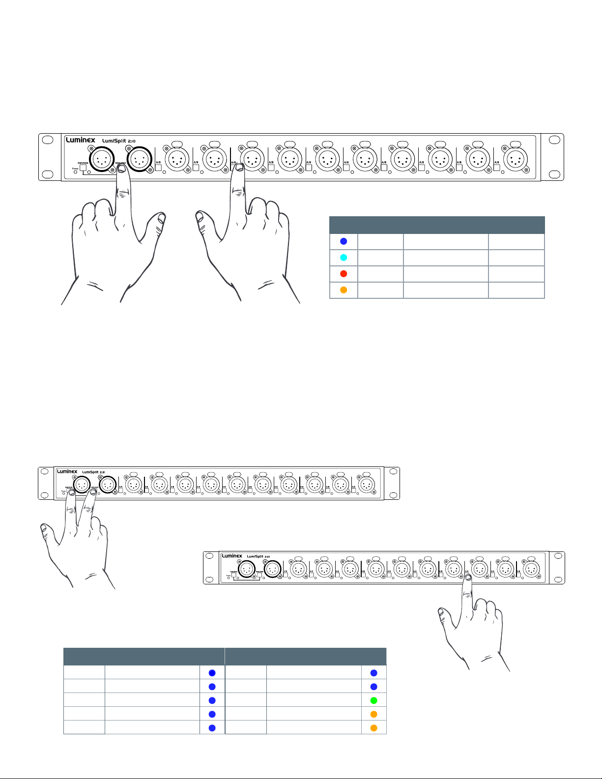
The LumiSplit now runs in A/B splitter mode.This is the default mode.
Backup mode (2)
Zone A input becomes the main input, Zone B the backup input. In the unlickely event of DMX loss on Zone A, the splitter will switch
automatically to zone B.
This mode can be used to create a backup situation for two Ethernet-DMX converters or two network processors. In case of failure of the first
device, the LumiSplit will automatically switch to the other device.
When DMX signal is lost on input A, A LED turns red, and all output LEDs turn red as well.This provides the user with a better indication that
the LumiSplit has switched to the secondary input.
When DMX signal is back available on input A, the A LED will turn blue again. However, to give control back to the input, you need to press
the A input button. All output LEDs will turn Blue/Cyan again.
You can give back control to input A through the control panel of LumiNet Monitor.
When the DMX signal on input B is NOT present both LEDs turn red
HTP merging mode (3)
The LumiSplit will merge the two DMX inputs according the HighestTakes Precedence policy.
RDM communication with connected end points is no longer active.
LTP merging mode (4)
The LumiSplit will merge the two DMX inputs according the LatestTakes Precedence policy.
RDM communication with connected end points is no longer active.
Regeneration on zone A (5)
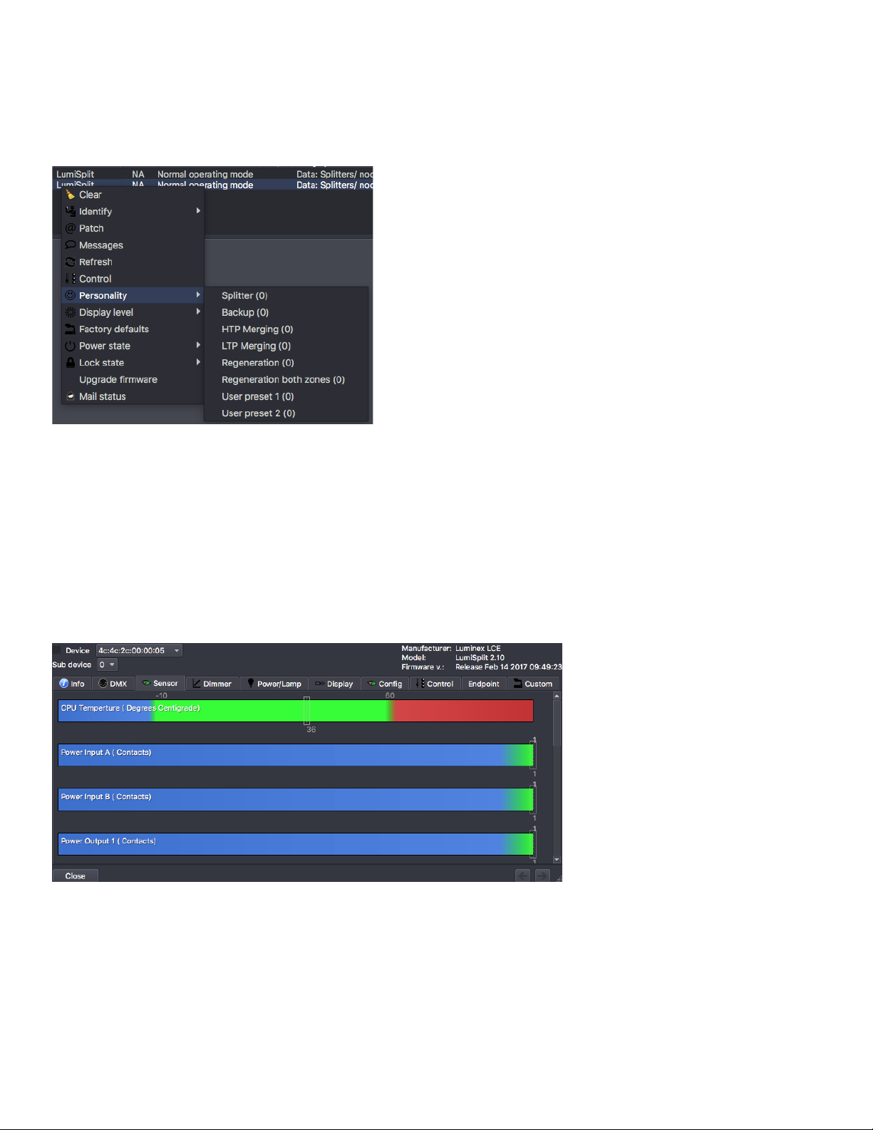
The LumiSplit will re-generate the incoming DMX signal with some new parameters.These parameters can be selected through LumiNet
monitor.
Regeneration on zone B (6)
Same as above for input B
Regeneration on all zones (7)
This mode allows you to quickly select regeneration mode for both inputs.The timing for each input will be set as described above.
RDM communication with connected end points is no longer active on both zones.
Dark mode (8)
Dark mode set the brightness of all LEDs to a low value.This avoids the LumiSplit generating too much light from its LEDs, where darkness
is a must have. Once you press one of the buttons on the front panel, the brightness will go back to full for a few seconds. Select the dark
mode again from the selection menu to disable it. Brightness can be set from LumiNet Monitor as well.
A: B:
A: B:
A: B:
A: B:
A: B:
A: B:
A: B:

User preset 1 (9) and 2 (10)
Two user profiles can be stored in outlet 9&10.This allows you to easily recall your favourite configuration, or al-
ternate between two configurations for different applications.To record a profile, and once in the selection mode,
simply hold one of the two buttons to store your conguration. Once the output LED start blinking
on its own, you can release the button. To recall the profile, once in selection mode, simply press on the
output button to reload the prole.These actions can be performed through LumiNet Monitor as well.
2.5 FRONT PANEL LOCK
For reliability reasons you can lock the front panel. In this way, nobody can accidentally change the settings of
the splitter during a live event for example. To lock and un-lock the front panel, press and hold the input
A button for 4 seconds. Once the power LED indicator blinks orange, release the button and the power
LED indicator will turn orange.The front panel is now successfully locked. Execute the same
procedure to unlock the front panel again.
The front panel can be locked/unlocked from LumiNet Monitor as well
2.6 FACTORY RESET
Sometimes it can come in handy to reset the entire device.To do that, press and hold the input A button
for 10 seconds. Once the power LED indicator blinks red, release the button.This will reset all settings to de-
fault. Please keep in mind that also all user presets will be deleted after this procedure.
The LumiSplit can be remotely reset from LumiNet Monitor as well.

3. THE NEW RDM EXPERIENCE
Not only can the LumiSplit provide you with some great features directly from its front panel, the unit can also be remotely configured and
monitored, all through RDM connectivity.
Once LumiNet Monitor is connected to a Luminex Ethernet-DMX converter with RDM enabled, the software will provide you with a com-
prehensive set of tools to monitor and configure your LumiSplit 2.10.
The LumiSplit 2.10 can be monitored and configured through any third party RDM controller.
Luminex recommends to use a Luminex converter and LumiNet Monitor to enter a new RDM experience.
LumiNet Monitor 2.1.6 or higer and LumiSplit firmware v5 or higher are necessary to take full benefit of all the features listed below.
3.1 DISCOVERY
The Lumisplit comes with two RDM responders (A & B). In the RDM panel, two responders will appear per splitter, if both are connected to
the RDM controller.
If you hover your mouse over one of the responders, additional information will be available.
Discovery is available from any RDM compliant controller.
3.2 IDENTIFY A LUMISPLIT
If your rack is filled with lots of LumiSplit, it can come in handy to identify a unit. Simply right click on one of the responders, and select
Identify>On. All LEDs will turn white and start flashing, to identify the unit. To stop the identification, repeat the same procedure and
select“o”, or click on the“Identify OFF”button on the top right end side of the RDM panel.
Identify is available from any RDM compliant controller.

3.3 LOCK/UNLOCK THE FRONT PANEL
To lock the device, simply right click on one of the responders, and select Lock state>Front Panel Locked.To unlock the device, repeat
the same operation, and select Lock state>unlocked.
Lock/unlock is available from any RDM compliant controller.
3.4 DARK MODE
The LumiSplit offers you to lower down the brightness of the LEDs. Right click on one of the responders, and select display level. Here
you can set the brightness either to low or full.There is no intermediate value available for the brightness of the LEDs.
Dark mode is available from any RDM compliant controller.

3.5 MODE SELECTION
You can remotely select one of the modes the splitter offers. Right click on one of the responders, and select the desired mode. Regeneration
mode is available for both responder.You then have to select the right responder (A or B) to assign the regeneration mode to it.
From here, you can reload profiles stored in outlet 9 and 10 as well.
Mode selection is available from any RDM compliant controller.
3.6 MONITORING
The RDM control panel enables you to monitor the status of all sensors embedded in the LumiSplit.The splitter comes with one temperature
sensor, and one sensor per DC/DC converter (input and output).To monitor the status of these sensors, right click on one of the responders,
select Control, and then, click on the Sensor tab.
The temperature sensor will indicate the actual inner temperature of the LumiSplit.The contact sensors will display the status of all DC/DC
converters. A DC/DC converter’s sensor with a value of 1 means the DC/DC converter is working correctly.
Sensor monitoring is available from any RDM compliant controller.

3.7 ENDPOINT VIEW
The LumiSplit 2.10 is the worlds first splitter to offer the endpoint view. Endpoints are any RDM compliant devices such as lighting fixtures,
smoke machines, lasers, or any remotely managed devices.
If RDM devices are connected to the ports of the LumiSplit, you’ll be able to know which port they are connected to.
By default, any RDM device will be listed in the RDM panel as follows:
In this example, the RDM test device is connected to port 1 of the converter using 2.0.0.12 as an IP address.
To see which port of the LumiSplit the device is connected to, right click on one of the responders of the LumiSplit 2.10, and select Control.
In the control panel, click on the endpoint tab:
If RDM devices are connected to the splitter, they will appear on each port marked with a white triangle on the left hand side. Simply expand
these lists, and discover the devices connected to the selected port.This feature makes your life easier when troubleshooting an installation,
to follow the complete signal path. Hover your mouse over the discovered RDM device to get some more info about it.

Zone assignation
In the endpoint view, you can also modify the zone assignment per port (1 or 2). Input A is universe 1, input B is universe 2.
To assign an output to one of these zones, simply click on the universe number of the selected output, and change the number, according
to your need.
RDM filtering
From this menu, you can enable/disable RDM filtering per port and per zone as well.
Simplytickthecorrespondingfiltercheck boxtoenable RDM filtering.Afilteredoutput willdisplay a light colouronitsLED (cyanororange).

Identify a port
If needed you can identify a port. To do so, simply tick the corresponding Identify check box, and the LED of the selected port will blink
white.This can come in handy when you need to indicate the port to use.
Regeneration
When in regeneration mode, click on the timing field of the selected input(s) to assign the desired regenerating timing.
Three different timings are available (BreakTime, Framerate):
• Slow (200µs/25FPS)
• Medium (184µs/36FPS)
• Fast (176µs/40FPS)
The timing set here will be available for all outputs linked to the selected input.
3.8 CUSTOM
Backup
Once the splitter is in backup mode, and in the unlikely event you loose DMX on input A, the splitter will automatically switch to input B. If
input A is back online, the splitter will not automatically give back control to input A.
Right click on one of the online responders, and select Control. Click on the Custom tab.

To give back control to input A , go the Backup menu, and click on the Set button. All output LEDs will turn blue again.
Store preset
The LumiSplit 2.10 offers you to remotely store a configuration on outlet 9 and 10. In the Store User Preset field, enter 1 if you wish to record
your first preset on outlet 9, enter 2 if you wish to record your second preset on outlet 10. Press the Set button to record your preset.
3.9 MESSAGES
The Lumisplit is able to send messages over RDM. You can then be notified about any change on the LumiSplit. To display the message
window, right click on one of the responders, and select Messages.

Luminex Network Intelligence - Slamstraat 13 - 3600 Genk, Belgium - +32 11 812 189 - suppor[email protected]
3.10 FACTORY RESET
The unit can be reset via RDM as well.To proceed, right click on one
of the responders, and select Factory Default.
3.11 FIRMWARE UPGRADE
The LumiSplit 2.10 is the first splitter to be upgradable through RDM.
To upgrade the unit, you’ll need a Luminex Ethernet-DMX converter
running 4.2.0 firmware or higher, and LumiNet Monitor 2.1.6 or higher.
Please bear in mind only one instance of LumiNet Monitor should be running
on the network during the firmware upgrade.
Download the latest LumiSplit firmware on our web site, and extract
the archive. Connect your computer to the node, and enable RDM on one port.
Connect this port to one of the two inputs of the splitter.
In LumiNet Monitor RDM panel, right click on one of the responders, and
select Upgrade Firmware.
Click on Select le, and select the extracted file (.bin).
Click on the Upgrade button, and the upgrade procedure will start.
The procedure ends once the progression bar reaches 100%.

Table of contents
Other Luminex Media Converter manuals
Popular Media Converter manuals by other brands

Radial Engineering
Radial Engineering 8cx manual

Transition Networks
Transition Networks SEPOE1011-150 user guide

Radial Engineering
Radial Engineering OX8 user guide

ESD
ESD CAN-CBX-AI420 manual

MRV Communications
MRV Communications Fiber Driver EM316SW-XY user guide

MADRIX
MADRIX Nebula Technical Manual & Quick Start Guide