Luminor Glacier UV LED GUV-4S User manual

FULLY INTEGRATED LED BASED
UV DISINFECTION SYSTEM
Operation &
Installation
Instructions
GUV-4S / GUV-5S modules

Table of Contents
1.0 Safety Consideraons..................................................................................................1
2.0 Before You Begin..........................................................................................................2
2.1 Tools & Materials ..........................................................................................................2
2.2 Water Quality Parameters ............................................................................................2
2.3 Locaon.........................................................................................................................2
3.0 Installaon ...................................................................................................................3
4.0 Operaon .....................................................................................................................4
4.1 GlacierGUV-4SController ............................................................................................4
4.2 GlacierGUV-5SController ............................................................................................5
4.3 GlacierGUV-5SOperaonalScreens............................................................................6
5.0 System Troubleshoong...........................................................................................7-8
6.0 System Specicaons .................................................................................................9
7.0 Expansion Modules ...................................................................................................10
8.0 Warranty.....................................................................................................................11
GUV-5S
module
GUV-4S
module

Page 1
Safety Considerations
AlthoughyourUVsystemhasbeenmanufacturedtothehighestsafetystandards,caremust
befollowedwhenoperangand/ormaintainingyoursystem.
1. Beforeservicingthisequipment,disconnectthepowercordfromtheelectricaloutlet.
2. Energy given o by the UV LED is harmful to your eyes and skin.NEVERlookdirectly
atanilluminatedUVLEDwithoutadequateeyeproteconandalwaysprotectyourskin
fromdirectexposuretotheUVlight.
3. Donotlookintotheinletoroutletopeningswhilethesystemispluggedintoelectrical
power.
4. Donotoperatetheunitifithasanydamagedormissingcomponents.
5. DonotopenoraempttoopentheGLACIERUVLEDsystemorpoweradaptor.
6. Therearenouser-replaceablecomponentsinsidetheGLACIERUVLEDsystem.
Contactthemanufacturerforserviceinstruconsifrequired.
7. Donotusethissystemforanypurposeotherthanwhatitwasintendedfor.Misuseof
thissystemcouldpotenallycauseharmtotheuserorothers.Useofthissystemdoes
notguaranteeanyparcularamountofreduconofmicroorganisms.
8. Yoursystemisintendedtobeinstalledindoorsandawayfromleakingplumbing.
DONOTplugtheunitinifthesystemoranyofthecomponentsarewet.
9. Toavoidelectricshock,ensurethatthe12VDCpowersupplyadaptorcomplieswith
localelectricalsafetycodes.The12VDCpoweradaptorshouldbepluggedintoaground
faultcircuitinterrupter(GFCI)typeofelectricACoutlet.AlsoensurethattheelectricAC
outletcomplieswithlocalelectricalsafetycodes.
10. Werecommendthatalicensedplumberorceredtechnicianinstallthesystem.
Any aempt to open the GLACIER UV LED system will void the warranty.
1.0
Page 2
Before You Begin
2.1 Tools & Materials:
• Screwdriver
• Drill
• Screws(x2)
• ⅜”TubeFingsforInletandOutletconnecons
• MounngHardware(ifrequiredforinstall)
2.2 Water Quality Parameters
UVdisinfeconisextremelyeecveagainstmicroorganismsbutonlyiftheUVlightcan
passthroughthewateritneedstotreat.Thismeansthatthequalityofyourwaterisvery
importantinordertoensurecompletedisinfecon.Treatedwatershouldbetestedforatleast
theparameterslistedbelow.IfthewaterexceedsthelistedparametersLUMINORstrongly
recommendsthatappropriatepretreatmentequipmentbeinstalled(equipmentrequiredwill
dependonparametersbeingtreated):
UVTransmianceabove90%.
Hardness:<1gpm(17mg/L)
Iron(Fe):<0.05ppm(0.05mg/L)
Manganese(Mn):<0.05ppm(0.05mg/L)
Turbidity:<0.1NTU
Tannins:<0.1ppm(0.1mg/L)
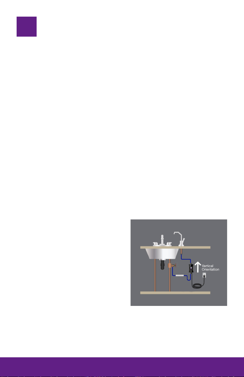
2.3 Location
ForPointofUse(POU)systems,installtheunit
justbeforethefaucet.Theunitmustbeinstalled
vercallyforcorrectoperaon.Ensurethere’s
enoughspacetofacilitatetheplumbingngs
aswellasanyrequiredpre-treatmentlters.
Waterowmustowfromtheboomofthe
unitupwardtowardsthefaucet.Makesure
youhavetherequiredplumbingconnecons
andpartsbeforeinstallaonaswellasasecure
locaontormlysecuretheunit.
[GUV-5S]Asolenoidcanbeinstalledaswellalongwiththesolenoidmodule(MOD-SOL)asan
accessorymodule.
PLEASE NOTE: All LUMINOR UV disinfecon systems are intended for indoor use only as
they should not be exposed to the elements.
2.0

Page 3
Installation
1. Makesuretheunitissecuredrmlyusingtwoscrewsinplace.MounngHardwaremay
beneededdependingoninstall
2. ConnectplumbingtotheBoomInletusingaPush-to-Connect⅜”TubeFing
3. ConnectplumbingtotheTopOutletusingaPush-to-Connect⅜”TubeFing
4. Fillandpressurizethesystemtocheckforleaksintheplumbing.Ifaleakisfound,
re-checkyourplumbing.
5. Plugthe12VDCpoweradaptorintoanappropriateACelectricaloutlet.Topreventrisk
ofshock,ensurethattheACoutletandpoweradaptorcomplywithlocalelectricalsafety
codes.
6. Pluginthe12VDCAdaptortotheBoomPowerPort.Thesystemshouldpoweron.
DO NOT OPERATE PRODUCT WITHOUT CONNECTING TO WATER SUPPLY.
3.0
Water outlet tube
Quickconnecttting
for 3/8” OD tube
Mountingscrew
Water inlet tube
Quickconnecttting
for 3/8” OD tube
Mountingscrew
12VDCpowerplug
IEPplugforoptional
accessorymodules
GLACIER
GUV-5S
SHOWN
UNIT MUST BE
INSTALLED
VERTICALLY WITH
WATER INLET ON
BOTTOM
WATER FLOW
DIRECTION

Page 4
Operation
Whenpoweredonwithnowaterow,theunitwillbeinStandbyModewiththeUVLEDs
turnedoawaingowtobeacvated.OnceowisdetectedtheUVLEDsareimmediately
acvatedtoprovideproperdisinfecon.Theunitwillautomacallylogthecumulaveamount
ofmethattheUVLEDsareturnedon,andtracktheamountofoperaonalliferemaining.
Onceowhasstoppedtheunitwillremainonfor10secondslongerbeforeshungothe
UVLEDs.WhenthemaximumoperaonallifeoftheUVLEDisreached,theunitwillnolonger
provideproperdisinfeconandhastobereplaced.IfatanypointduringoperaontheUV
LEDsoverheatandexceedtheOvertemperatureAlarmThreshold,thesystementersacool
downperiodduringwhichtheUVLEDsaredisabledunlthetemperaturedropsbelowthe
OvertemperatureAlarmReleaseThreshold.Duringthecooldownperiodthesystemnolonger
providesdisinfecon.RefertoOperaonandSpecicaonsfordetails.
4.1 GLACIER GUV-4S Controller
Mul-StateStatusLEDindicangpower,ow,LED
lifeandovertemp./failalarms.Automacdetecon
ofwaterowprovideson-demanddisinfecon,
lowenergyuse&preventsheatbuild-up.
Status LED Descripon Audible
Alarm
Water Safe for
Consumpon?
Solid Green UnitisinStandbyModewaingforow,UV
LEDsarenotacve. NO YES
Flashing
Green
SystemdetectsowandhasacvatedtheUV
LEDsforproperdisinfecon. NO YES
Solid Red EndofSystemlife,replaceunit. YES NO
Flashing Red UVLEDshavefailedandnolongercanprovide
disinfecon. YES NO
Flashing Red
& Green
UVLEDsareoverheang;thesystementers
acooldownperiodandnolongerprovides
disinfeconunlUVLEDtemperaturedrops
below50°C.
YES NO
4.0
Page 5
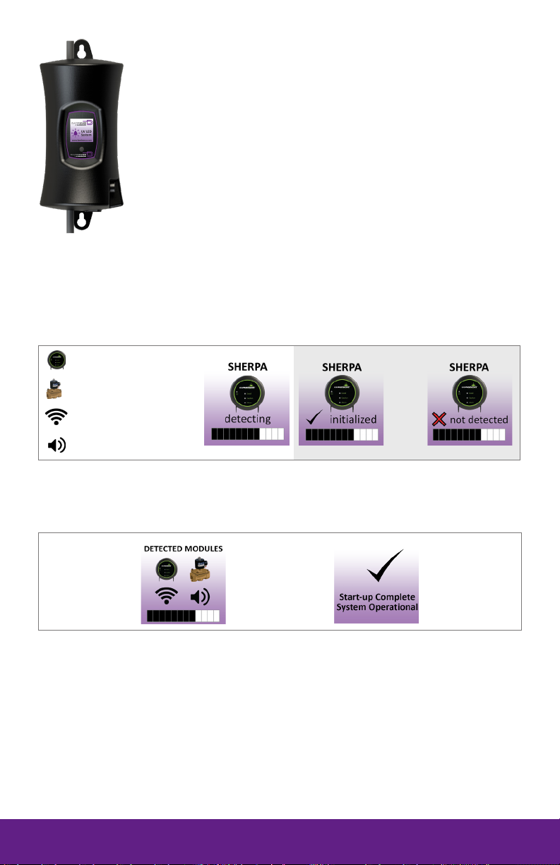
4.2 GLACIER GUV-5S Controller
AfullcolourLCDscreenprovidestheuserwitha
detaileddescriponofthesystem’sperformance
inaddiontoprovidinganyapplicablefault
messagesandsystemdiagnoscs.
Power-On Sequence
OnStart-up,thesystemwillrunthroughadiagnosccheckandinializeanyoponalmodule
thatmaybeaachedtothesystem.
Oponal Modules: Solenoid, WiFi, Remote Alarm, Sherpa
SHERPA
OR
Solenoid
WiFi
Remote Alarm
Analmodulescreenisdisplayedshowingwhichspecicmoduleswereinializedandthen
proceedtonormalsystemoperaon.Thetotallengthofthestart-upprocedureislessthan30
seconds.

Page 6
4.3 Operational Screens (GUV-5S only)
Screen Condion
HOME/
UV LED STATUS
STANDBY MODE
Noowpresent,UVLEDsareo.
UV LED ACTIVE
Flowdetected,UVLEDSareacveand
disinfecngwater.
LED LIFE
REMAINING Thesystemtrackstheoperaonallifemeof
theUVLEDs.ThisdisplayedasLEDLife(Hours)
remaining
EachSystemsUVLEDshaveupto5000Hours
Lifeme.
TEMPERATURE
SCREEN
DisplaysthetemperatureoftheUVLEDs
CONTACT
SCREEN
Displayscompanyinformaon
QR CODE
AQRcode(QuickResponsecode)isamatrix
barcoderstdesignedfortheautomove
industry.LUMINORusestheQRcodetostorea
linktoaspecicpageonourwebsite.
INFO SCREEN
DisplaysPartNumber,On/OCyclesandthe
SystemRunningTime.
Page 7
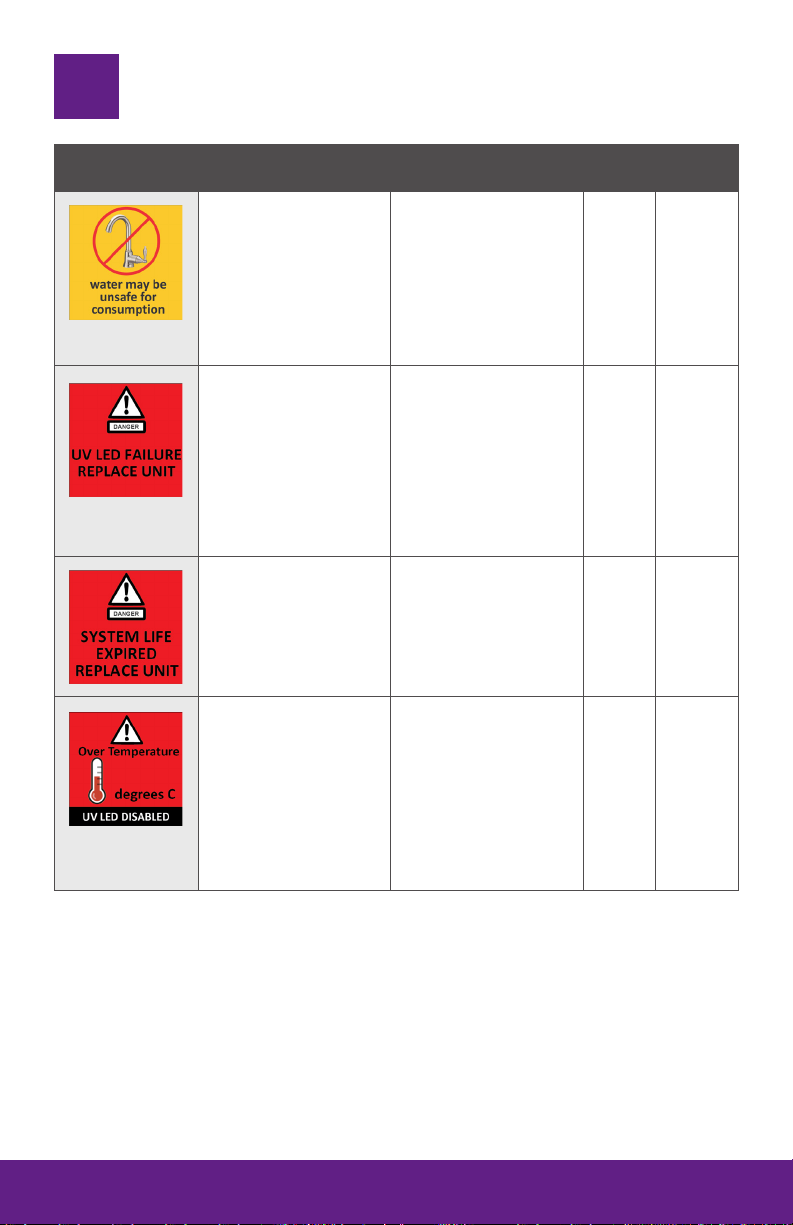
System Troubleshooting
System Display Problem Resoluon Water
Safe? Alarm
A major alarm has
occurredwhich
preventsproper
disinfeconofthe
water.Thisscreen
togglesevery4seconds
to alert the user
waterisnotsafefor
consumpon.
Performacontox
acvemajoralarm.
RefertoAlarmsBelow.
NO N/A
The system has
detectedaproblem
withtheUVLEDs.
Powerothesystemfor
10seconds,andpower
onagain,ifalarmissll
present,replaceunit
withthepartindicated
onthesilverlabelon
thebackorontheInfo
Screen.
NO Constant
Beeps
AlthoughtheUVLEDs
arepoweredandvisibly
illuminated,duetothe
LEDsageitsUVoutput
isnolongersucient
forproperdisinfecon.
Replaceunitwiththe
partindicatedonthe
silverlabelontheback
orontheInfoScreen.
NO Constant
Beeps
TheUVLEDsare
overheang,the
systementersacool
downperiod,disabling
theUVLEDsunlthe
temperature reaches a
safeoperaonallevelto
enabletoLEDs.Referto
specicaonsformore
details.
Make sure the
waterandambient
temperatureiswithin
theratedspecicaons.
Verifysystemisinstalled
vercally;horizontal
installaonresultsinair
bubblesbeingtrapped
intheunit.
NO Constant
Beeps
5.0
60

Page 8
System Display Problem Resoluon Water
Safe? Alarm
Abadconneconhas
beendetectedinthe
IEPport.
Ensureallmodulesare
connectedproperlyto
thesystemandtoeach
other.
Modulescanbetested
individuallybyplugging
inoneatameand
cyclingpowertothe
system.
Replaceanymodule
thatisnotdetected
whenpluggeddirectly
intothecontroller
YES
2 beeps
every30
seconds
Themodule
indicatedisnolonger
communicangtowith
the system
YES
2 beeps
every30
seconds
TheUVLEDremaining
hoursislessthan8but
hasyettoexpire.
Userneedstostart
considerreplacingunit
soon.Thepartnumber
isindicatedonthesilver
labelonthebackoron
theInfoScreen
YES
2 beeps
every30
seconds
This manual suits for next models
1
Table of contents
Other Luminor Water Filtration System manuals


Popular Water Filtration System manuals by other brands

Wisy
Wisy LineAir 100 Installation and operating instructions

Schaffner
Schaffner Ecosine FN3446 Series User and installation manual

Pentair
Pentair FLECK 4600 SXT Installer manual

H2O International
H2O International H20-500 product manual

Renkforce
Renkforce 2306241 operating instructions

Neo-Pure
Neo-Pure TL3-A502 manual


