[2]Luminosoled.com
LEAVE A COPY FOR THE USER / MAINTENANCE ENGINEER
FOR FUTURE REFERENCE
locking bolts
Hinged hatch
2
Cover
STEP 2:
Pole
Locking bolts
1
Locking nuts
Rotatable tenon
STEP 1:
3
Mains power
supply cord
Cable gland
Rotatable tenon
Bubble level
STEP 3:
4
5
Photocell
-20°
+20°
-20°
+20°
-+20 degrees adjustable
Screws to adjust and lock rotatable tenon
STEP 4:
STEP 5:
WIRING INSTRUCTION
Terminal Block
LIVE
GROUND
NEGATIVE
LIVE -Black
NEGATIVE -White
GROUND-Housing
Mains power supply
LED DrivER
L
G
N
6
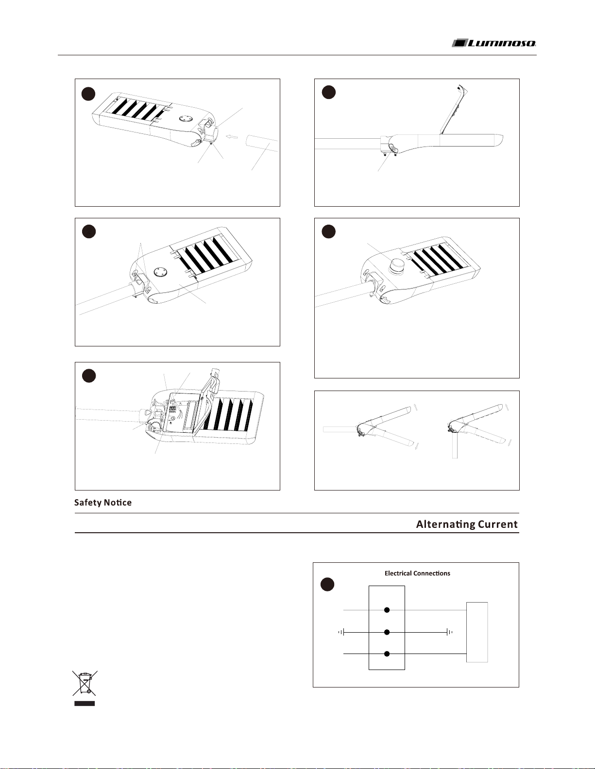
To adjust lng angles from front to back, first loosen the screws on both
sides of the rotatable tenon using 6mm hex wrench or its equivalent, see Figure 4.
Secondly locate the lt and adjust by ghtening the menoned screws at
45 N.m.torque. To adjust the fixture from side to side, loosen the pole locking bolts, see Figure 1,
when ready, ghten the pole locking bolts at 45 N.m, then ghten the pole locking nuts at 10 N.m
torque so as to ensure the lighng fixture is installed to the pole firmly.
Installation Instruction & Installation Steps
Loosen nuts from pole locking bolts, then slide fixture on to pole through opening (tenon) on the
rear of housing. See Figure 1.
Run main power supply cord into led driver compartment via cable gland, and use open spanner or
similar tool to lock the gland to main power supply cord ghtly. See Figure 3.
Slide fixture to the inner end of tenon, then ghten locking bolts
with 5mm hex wrench or its equivalent to ensure the fixture is fixed to pole firmly.
See Figure 1.
Loosen hinged hatch locking bolts with 5mm hex wrench or its equivalent, and open the hatch for
led driver compartment access.
See Figure 2.
STEP I: Connect the LIVE wire in the main power supply cord to the
L marked hole In the terminal block , and ghten the connecon
properly.
STEP II: Connect the NEGATIVE wire in the main power supply cord to
the N marked hole in the terminal block , and ghten the connecon
properly.
STEP III: Connect the YELLOW/GREEN GROUNDING wire in the main
power supply cord to the G marked hole in the terminal block ,
and ghten the connecon properly.
Input wire H07RN-F 3x1.5mm² (SJOW 3 * 18AWG) or rubber sheathed
cable (not supplied).Conductor must have a minimum cross-seconal
area of 1.0mm² (18AWG).
This logo indicates that this product must not be disposed of with other
waste. Please recycle used lamps to prevent environmental hazard and
threats to human health resulng from improper disposal. STEP 6:
Reference “Electrical Connecons” secon for compleng electrical
connecons.
See Figure 6


