manuals.online logo
Brands
  1. Home
  2. •
  3. Brands
  4. •
  5. Luxlink
  6. •
  7. Microphone System
  8. •
  9. Luxlink TVS-1002 User manual

Luxlink TVS-1002 User manual

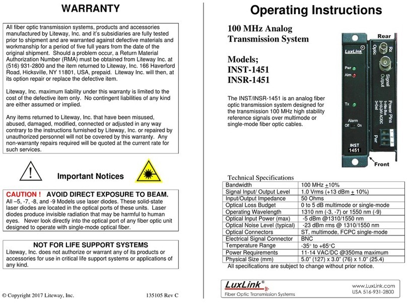
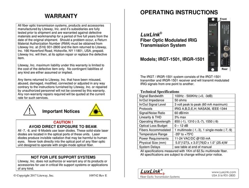
WARRANTY
All fiber optic transmission systems, products and accessories
manufactured by Liteway, Inc. and it’s subsidiaries are fully tested
prior to shipment and are warranted against defective materials and
workmanship for a period of five full years from the date of the
original shipment. Should a problem occur, a Return Material
Authorization Number (RMA) must be obtained from Liteway Inc. at
(516) 931-2800 and the item returned to Liteway, Inc. 166 Haverford
Road, Hicksville, NY 11801, USA, prepaid. Liteway Inc. will then, at
its option repair or replace the defective item.
Liteway, Inc. maximum liability under this warranty is limited to the
cost of the defective item only. No contingent liabilities of any kind
are either assumed or implied.
Any items returned to Liteway, Inc. that have been misused,
abused, damaged, modified, connected or adjusted in any way
contrary to the instructions furnished by Liteway, Inc. or repaired by
unauthorized personnel will not be covered by this warranty. Any
non-warranty repairs required will be quoted at the current rate for
such services.
Important Notices
NOT FOR LIFE SUPPORT SYSTEMS
Liteway, Inc. does not authorize or warrant any of its products or
accessories for use in critical life support systems or applications of
any kind.
© Copyright 2017 Liteway, Inc. 136433 Rev B
Operating Instructions
LuxLink®
Lightning/Surge
Protector
Model TVS-1002
The LuxLink®TVS-1002 is a weatherproof module tat is designed to
protect delicate input signal and power lines of many fiber optic products
from damage due to power surges, nearby lightning strikes and similar
excessive electrical discharges.
Technical Specifications
Signal Voltage Range 0 to + 5 volts (non polarity sensitive)
Signal Coupling DC coupled
Signal Clamping Voltage + 7.5 volts
Signal Line Impedance 4 ohms typical (per input to output line)
Signal Type Analog or Digital
Power Throughput 0 to 13 Volts DC (polarity sensitive)
Power Current Capacity 0 to 1 ampere continuous
Power Clamping Voltage 15 Volts typically
Power Line Impedance 1 ohm maximum (per input /output line)
Signal/Power Connectors Screw-type Terminal Blocks
Operating Temperature -35to +65C
Physical Size (mm) 3.5” (89) x 3.1” (79) x 1.9” (48)
All specifications are subject to change without prior notice.
!
Power Input Signal
Input Signal
Output
Power Output
Earth Ground
Installation Instructions
The diagram below shows a typical installation of the TVS-1002
Lightning/surge Protector.
The recommended installation procedure is as follows:
1. Remove circuit board by removing ground terminal hex nut and
crimp lug.
2. Mount housing in the desird location using the 2 mounting
holes on the rear of the housing.
3. Insert a bare wire gound lead of 14AWG (or larger) copper wire
through the sealing grommet on the side of the housing and
crimp onto the ground crimp lug. Connect the opposite end of
the ground wire to a suitable earth ground. The better this
ground is, the more effective the overall supression level will
be.
4. Replace the circuit board into the housing, slide the ground
crimp lug on to the ground stud and secure with the ground
terminal hex nut.
5. Connect the power leads to and from the fiber optic equipment
being protected as per the diagram below. Be sure to observe
the correct polarity of the power leads. The internal supression
devices are polarity sensitive with regard to power leads and
must be connected as shown or the unit may be damaged.
6. Connect the signal leads. AC or DC signals within the ranges
specified may be used. Note the polarity of the signal terminals
which represent the inout and output lines. For best results
with DC signals utilize these polarities since the + signal input
is connected to the + signal output and vice versa. For AC
signals if the phase relationship is desired, be sure to observe
these connections.
Note that one or both signal lines may be used as desired.
7. Route all wires through the sealing grommet on the housing.
136433 Rev B
Power and Signal Connections
Power/Signal Terminal Block Connections
Pin Function
1 Operating Power + input
2 Operating Power - input
3 Signal + input (phase A)
4 Signal - input (phase B)
5 Operating power + output
6 Operating power - output
7 Signal + output (phase A)
8 Signal - output (phase B)
Be certain to check all connections, before applying power
Note that the power input to output impedance is 1 ohm or less.
Also note that the signal input to output impedance is typically 3 ohms.

Other Luxlink Microphone System manuals

Luxlink IRGT-1501 User manual

Luxlink

Luxlink IRGT-1501 User manual

Luxlink INST-1451 User manual

Luxlink

Luxlink INST-1451 User manual

Popular Microphone System manuals by other brands

Gotting HG G-7335xZA Series Device description

Gotting

Gotting HG G-7335xZA Series Device description

Azden 300UPR user guide

Azden

Azden 300UPR user guide

Sony DWA-01D Brochure & specs

Sony

Sony DWA-01D Brochure & specs

Toa WS Series operating instructions

Toa

Toa WS Series operating instructions

Surtek Adaptador User's Manual and Warrantly

Surtek

Surtek Adaptador User's Manual and Warrantly

Electro-Voice Telex RE-2 Brochure & specs

Electro-Voice

Electro-Voice Telex RE-2 Brochure & specs

Hollyland COSMO 1200 manual

Hollyland

Hollyland COSMO 1200 manual

DIGITECH Audio AM-4114 user manual

DIGITECH Audio

DIGITECH Audio AM-4114 user manual

Shure SCM410 user guide

Shure

Shure SCM410 user guide

LD LDU300 user manual

LD

LD LDU300 user manual

Alto MOD-800R Service manual

Alto

Alto MOD-800R Service manual

SeeEyes SC-IPT3001E user manual

SeeEyes

SeeEyes SC-IPT3001E user manual

AKG Perception WMS45 User instructions

AKG

AKG Perception WMS45 User instructions

Sony UWP-V1 operating instructions

Sony

Sony UWP-V1 operating instructions

Sony DWZB30GB brochure

Sony

Sony DWZB30GB brochure

Sennheiser SK 250 specification

Sennheiser

Sennheiser SK 250 specification

Sound Town SWM26-U2 Series product manual

Sound Town

Sound Town SWM26-U2 Series product manual

Hollyland MARS 400S user manual

Hollyland

Hollyland MARS 400S user manual

manuals.online logo
manuals.online logoBrands
  • About & Mission
  • Contact us
  • Privacy Policy
  • Terms and Conditions

Copyright 2025 Manuals.Online. All Rights Reserved.