Lynton Luminette Q User manual


CONTENTS
1. GENERAL INFORMATION 1
1.1 Introduction 1
1.2 Product Overview 1
2. SAFETY 3
2.1 General Safety 3
2.2 Laser Radiation 4
2.3 Electrical Safety 5
3. OPERATION 7
3.1 Introduction 7
3.2 Installation 7
3.2.1 Delivery & Unpacking 7
3.2.2 Parts List 7
3.2.3 Electrical Supply 8
3.2.4 Cooling Water Requirements 8
3.3 System Familiarisation 9
3.4 Operating the Luminette Q Laser System 12
3.5 Changing Handpieces 15
3.6 Interlock Warning Screen and LEDs 16
4. CLEANING AND MAINTENANCE 19
4.1 Cleaning 19
4.2 Maintenance Schedule 19
4.3 Maintenance Procedures 19
4.3.1 Topping up the Cooling Water 19
4.3.2 Filling the Cooling System from Empty 20
A1. SPECIFICATIONS 21
A1.1 System Classifications 21
A1.2 System Specifications 21
A1.2.1 Luminette Q Parameters 21
A1.2.2 Output Parameters 21
A1.2.3 Physical Parameters 22
A1.2.4 Optical Parameters 22
A1.2.5 Electrical Parameters 22
A1.2.6 Environmental Parameters 22

1
________________________________________________________________________________
1. General Information
1.1 Introduction
This manual contains instructions for the safe operation of the Luminette Q
Laser Systems manufactured by Lynton Lasers Ltd. Service and Maintenance
of the system forms the subject matter of a separate Service Manual. A
Luminette Q Training Manual is also available which contains
recommendations on the many clinical applications of the Luminette Q
System.
1.2 Product Overview
There are currently three models in the Luminette range of IPL/laser systems,
the standard Luminette System, the Luminette Advance system and the
recently introduced Luminette Q system. All of these models look similar
from a physical and operational perspective. However, there are significant
differences which will be highlighted in the relevant sections of this manual.
The Luminette Q System is a source of high intensity Q-switched laser output
for a number of different applications in Cosmetic Dermatology. Based on a
state-of-the-art laser technology the Luminette Q System is capable of
delivering pulse fluences of up to 22.6J/cm2from a compact, portable,
NOTE : The Luminette Q handpieces are not compatible with the Standard
& Advance Luminette systems and vice versa.

2
________________________________________________________________________________
desktop unit. Furthermore, the use of a water-to-air cooler in the cooling
system and an efficient switched-mode power supply allows the Luminette Q
Laser System to be operated from only a standard 13 Amp mains outlet. No
other connections are required.
The Luminette Q Laser System is menu driven using a blue LCD display and
stylish chrome-finish illuminated buttons. Pre-set default parameters are
included for the different Skin Types, all determined through clinical
experience.
The output of the Luminette Q Laser System comprises of passively Q-
switched laser output from a range of ergonomically designed detachable
handpieces. A range of different interchangeable spotsize spacer attachments
serve to deliver the light directly to the treatment area on the skin.
The Handpieces themselves store their own unique identifier, calibration
factor and flashlamp count record, a feature that allows them to be swapped
between Luminette Q Systems and also allows remote servicing without any
User intervention.

3
________________________________________________________________________________
2. Safety
2.1 General Safety
(i) Labels:
The labels attached to the Luminette Q System are described in Appendix A1.
(ii) Handling:
The Luminette Q System, complete with cooling water and handpiece, weighs
in excess of 20kg. It is therefore recommended that lifting or carrying the
Luminette Q System from place to place should be undertaken by two people,
each person holding one of the side handles.
(iii) Read the User and Training Manuals:
You are strongly advised to read this User Manual carefully before operating
the Luminette Q Laser System for the first time. Systems may be optically or
electrically damaged if not operated systematically and with a thorough
knowledge of the function of each component.
Users are particularly recommended to read the accompanying Training
Manual before using the Luminette Q System for its intended purposes in
cosmetic dermatology.
CAUTION : The Luminette Q Laser System should not be used in the
presence of explosive gases or gas mixtures.
CAUTION : In the UK, the Luminette Q Laser System should be used at all
times in accordance with the Health and Safety at Work, etc., Act, 1974.
CAUTION : Use of controls or adjustments or performance of procedures
other than those specified herein may result in hazardous light exposure.
CAUTION : Non-Professional Users of the Luminette Q Laser System
should undertake a course of Training before carrying out any actual
treatments. Lynton Lasers Ltd does not accept any responsibility for the
actions of inadequately trained users.
CAUTION : The Luminette Q Laser System should only be used by, or
under the supervision of, a qualified medical practitioner, unless National
Regulations or Guidelines state otherwise.

4
________________________________________________________________________________
(iv) Keep Records:
You are further recommended to keep a regular record of all maintenance or
repair procedures carried out on the Luminette Q System. By doing this the
causes of sudden performance loss can be more immediately diagnosed.
2.2 Laser Radiation
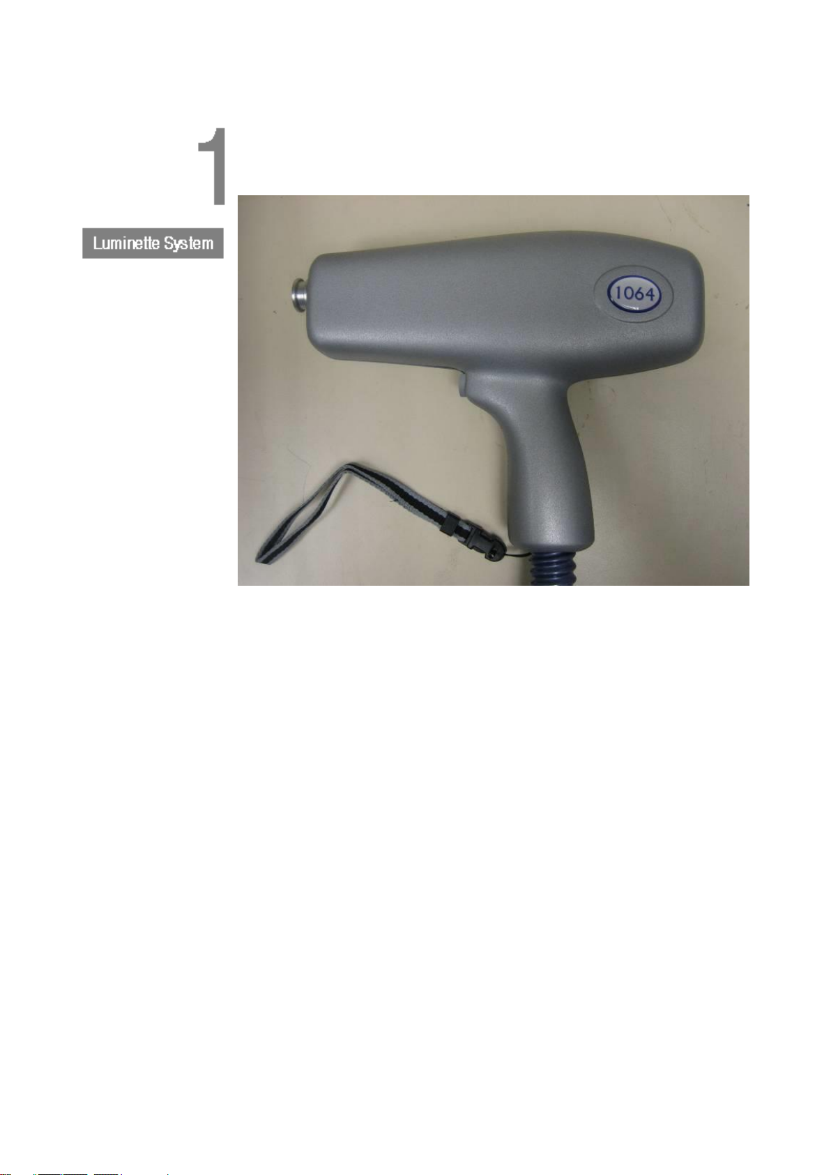
The laser radiation emitted by the Nd:YAG Handpiece on a Luminette Q Laser
System is at the following wavelength;
Wavelength Radiation Visibility
•1064nm. Infrared COMPLETELY INVISIBLE
•532nm Green VISBLE
The wavelength emitted by a particular laser system is specified on the
warning logo. The eye will transmit most of this laser radiation directly to the
retina which can be severely damaged. All specular or diffuse reflections
from objects external to the handpiece are dangerous. If the user is in any
doubt about the distribution of laser radiation either internal or external to the
Nd:YAG Handpiece on a Luminette Q Laser System it is recommended that
suitable detecting equipment should be used.
The radiation classed as completely invisible may interact with any surface on
which it impinges to produce visible light. The user is warned that even this
light may be hazardous and that he or she should maintain maximum care at
all times. Damage to other parts of the body other than the eye will be a
function of the power level of the laser and of the exposure time.
A suitable set of eyewear for use with the Q-Switched Output must have
OD≥6(ideally 7 or more) at both 1064nm and 532nm, must be rated
according to BS EN207:1999 and must be CE-marked. Contact Lynton Lasers
Ltd for recommended eyewear.
Access to laser areas should be restricted to personnel whose work requires
operation of the laser. These personnel must be instructed in the necessary
safety procedures. Warning signs placed near the laser area are also
recommended.
Read and adhere to the specific WARNING information attached to the
Luminette Q system, and contained within this manual.
WARNING: Laser goggles/glasses of the approved type MUST be worn by
personnel at all times during operation of a Luminette Q System. These
goggles/glasses must be effective at the wavelengths that can be generated.

5
________________________________________________________________________________
2.3 Electrical Safety
When the Luminette Q Laser System is operated from the control panel with
all covers in place and a Detachable Handpiece properly connected it does not
present the operator with any electrical hazard.
When Detachable Handpieces are being changed over there are no hazardous
voltages on any of the electrical connections. These connections are
shrouded with insulating material as an added safety precaution.
WARNING : The Luminette Q Laser System MUST NOT be operated by
unauthorised personnel with any covers removed.


7
________________________________________________________________________________
3. Operation
3.1 Introduction
This chapter contains all the information necessary for the successful
operation of the Luminette Q Laser System. Initially, the installation of the
system is considered, followed by a more detailed description of the different
parts of the system. The operator is then taken step by step through a largely
self-explanatory operating procedure in which the Luminette Q System is
turned on, the parameters are selected, the treatment is performed and the
system is switched off again. Recommendations on treatment procedures are
made in an accompanying Training Manual.
3.2 Installation
3.2.1 Delivery & Unpacking
The Luminette Q Laser System is despatched in a crate designed to protect
the equipment when subject to normal shipping and handling procedures.
Upon arrival the crate should be inspected to ensure that it has not been
unreasonably damaged during transit. If the crate has been damaged it is
recommended that the supplier is contacted immediately. It will then be
recommended that photographs are taken during the unpacking process. If
the crate is undamaged it can be carefully unpacked. The environmental
conditions pertaining in any room in which the Luminette Q Laser System is
to be used or stored must comply with the temperature and humidity
requirement specified in Appendix A1. Ideally the room would be air-
conditioned. It is also recommended that the crate and packaging material are
retained in case the Luminette Q System needs to be returned to the
manufacturer for any reason. The manufacturer will not accept any liability for
damage to a Luminette Q System caused by inadequate packaging when
being returned.
3.2.2 Parts List
Each Luminette Q System should comprise of the following basic Parts List:
Item Quantity
•
Luminette Cabinet 1off
•
Handpiece Assembly (dependent on order) A/R
•
Start Keys 2off
•
Mains Lead 1off
•
Door Interlock Plug 1off
•
User Manual 1off
•
Test Sheets 1off

8
________________________________________________________________________________
•
Water Top-up Bottle (500ml) 1off
•
User and/or Patient Eyewear (for 1064 & 532 Handpieces) 2off
•
Patient Total Blackout Eyewear (for 1064 Handpiece) 1off
3.2.3 Electrical Supply
A standard Luminette Q Laser System can operate from AC mains supplies
from 100-125V or 200-264V as long as there is also a separate Earth lead.
The fusing, however, depends on the mains supply as follows:
200-264V AC mains supplies : 5A fuses (2 off)
100-125V AC mains supplies : 10A fuses (2 off)
3.2.4 Cooling Water Requirements
A standard Luminette Q Laser System contains a closed-loop water-to-air
cooling system that requires about 1.2 litres of deionised water to operate
correctly. If the Luminette Q System has been shipped overseas it will have
been done so with the cooling system emptied of water. It will therefore need
refilling before the system can be used.
A procedure for filling the Luminette Q cooling system with deionised water is
given in Section 4.3.2 of Chapter 4: Cleaning & Maintenance.
Because the internal cooling system requires an air vent (a small hole in the
pipe of the reservoir filling point) to operate properly, it is likely that over time
some of the cooling water will evaporate and the cooling system will need
topping up with additional deionised water. The User will know that the water
needs topping up when the following conditions occur :
▪The pump doesn't come on when the keyswitch is turned on, and an
Interlock Warning message is displayed on the screen.
▪Interlock LED No.3 on the back panel will be lit, indicating low water level.
When these conditions occur top up the deionised water following the top-up
procedure given in Section 4.3.1 of Chapter 4 : Cleaning & Maintenance.
WARNING: The equipment MUST be adequately earthed. Ensure that the
earth lead in the supply cable is connected to the earth lead of the electrical
supply in the area where the Luminette Q Laser System is to be used.
WARNING: The equipment MUST NOT be used without first filling the
cooling system with the requisite amount of deionised water. Deionised
water will be supplied by either Lynton Lasers Ltd or one of its designated
agents or distributors.

9
________________________________________________________________________________
3.3 System Familiarisation
The controls on the Luminette Q Laser System are the same as those for all
Luminette Systems and are shown in the following diagram:
(1) Emergency Stop Button
Pressing down on this button shuts off ALL power to the system. The
latching button requires a twist to release it and restore the power.
(2) Key Switch
Turning the key switch clockwise turns the Luminette Q System on but only
into Standby Mode. In this state the LCD is powered up and the buttons are
waiting to be pressed. The key cannot be removed in this position. Turn the
key switch counter clockwise to turn the Luminette Q System off again at any
time. Remove the key and store in a safe location when the Luminette Q
System is not in use.
(3) Control Buttons (4 off)
The 4 illuminated buttons on the Front Panel are used to both control the
action of the Luminette Q System and to select the various operating
WARNING: Do NOT store or transport the Luminette Q System, or any of its
detachable Handpieces, at temperatures below ~5oC. The water in the
cooling system could freeze and damage the various elements of the cooling
system, particularly the laser rod, flowtube or flashlamp in the Handpieces.
This could then result in a serious leak and further damage to the Luminette
Q System or Handpieces.

10
________________________________________________________________________________
parameters. Parameters available include the Fluence, the Spotsize and the
Repetition Rate.
(4) LCD Display
The main User Interface of the Luminette Q System. Used in conjunction with
the 4 Control Buttons, the operation of the Luminette Q is controlled here.
(5) Detachable Handpiece Socket
The point at which the various Detachable Handpieces are connected to the
Luminette Q System.
The back panel of the Luminette Q System is shown below:
(6) Fused Mains Inlet
Pulling out the detachable mains lead from this socket removes all power
from the Luminette Q System. Alternatively the mains lead can unplugged
from the wall socket, or switched off at the wall socket if it is a switchable
supply. The value of the mains inlet fuses (supply "live" AND “neutral”) will
depend on the mains voltage at the location at which the Luminette Q System
is used.
(7) Shot Counter
This feature is not currently functional on the Luminette Q Laser System.
(8) External Interlock Socket
An external interlock facility is provided by means of the Jack socket next to
the mains inlet socket on the back of the Luminette Q System. A shorting

11
________________________________________________________________________________
Jack plug is provided if operation without a remote interlock is required.
Local safety standards, however, will often require the use of an external (e.g.
door) interlock. The interlock circuit is available between the two ways of the
Jack socket.
(9) Interlock Status LEDs
The interlock status of the system is described by a row of 8 red LEDs on the
back panel of the cabinet. If any one of these is lit it will be impossible to
deliver light from the handpiece. A description of the meaning of the
individual LEDs comes later.
(10) Reservoir Filling Point
The internal cooling system can be topped up at this point using the pipe
provided. The pipe is normally fitted with a two-position cap. In normal use
the cap must not obstruct the air vent in the top of the filling pipe.
(11) Nd:YAG Laser Handpiece
Each handpiece contains a Xenon flashlamp and Nd:YAG laser rod within a
ceramic reflector and a high reflecting mirror which form a compact laser
cavity. This cavity is the source of laser output produced by the Luminette Q
System. The lamp and laser rod are water cooled. The water and power are
delivered through the flexible conduit or umbilical. This conduit is connected
to the front panel of the Luminette Q System using the custom detachable
Plug/Socket arrangement shown below.

12
________________________________________________________________________________
The Handpiece can be set up to deliver different spots sizes. This is achieved
by simply inserting the chosen Spot spacer into the end of the handpiece as
shown above. Each Spot spacer is labelled with the spot diameter (in mm).
During operation the handpiece is held such that the spotsize spacer makes
contact with the patient's skin and the laser pulse is initiated by depressing
the pushbutton at the top of the handle of the handpiece.
3.4 Operating the Luminette Q Laser System
The follow sections outline the basic control sequences for operating the
Luminette Q Laser System. The control panel has been designed to be logical
and simple to use. If in any doubt the user is reminded that any of the
following actions, performed at any time, will remove the possibility of the
emission of light:
(i) Turning the key switch counter-clockwise to the OFF position.
(ii) Pressing the Emergency Stop Button.
(iii) Switching off or disconnecting the mains from either the back of the
Luminette Q System or at the plug socket on the wall.
Whenever the Luminette Q System is to be used the operator must ensure
that the back of the cabinet is not flat against a wall or any other piece of
equipment or furniture. The air outlet vents must have at least 15cm of free
WARNING : Failure to provide adequate ventilation at the back of, and
underneath, the cabinet during operation of the Luminette Q System will
result in the system shutting down or in some cases may result in damage
to the system. Never sit the Luminette Q System directly onto a flat surface
smaller than the footprint of the device. Always stand the Luminette Q
System on its feet.
WARNING: when the laser handpiece is not in use the user should replace
the safety beam stop

13
________________________________________________________________________________
space to operate efficiently. The user must also ensure that air can flow freely
underneath the Luminette Q System. The air inlet vents are in the base plate
of the cabinet and must not be blocked.
The Luminette Q System must first be plugged into the mains and the room
mains supply switched on if a switch is present.
Turning on the keyswitch will start up the system. The Welcome Screen will
appear on the LCD and it will be possible to hear the low hum of the internal
water pump and cooling fan. The blue illuminated pushbuttons will also
strobe, if enabled.
Lynton-Lasers-Ltd LUMINETTE Q
WELCOME
=========-
After about 2 seconds the Welcome screen will automatically change to the
Standby Screen shown below.
Lynton Lasers Ltd LUMINETTE Q
Shots--: 130 Status-: STANDBY
Spot---: 3mm HP-----: 1064nm
<Shutdown> <Spot-> <Spot+> <Treat>
This is an example of the main Standby Screen, from where operating
parameters can be selected and the system can be enabled for treatment.
This Standby screen displays the handpiece type currently connected to the
Luminette Q system in the “HP” area of the screen.
As can be seen, the screen can be used to choose the treatment spot size.
The spot size is shown on screen and can be adjusted by pressing the <Spot-
> (decrease) and <Spot+> (increase) buttons. The spot sizes available will
depend on the particular Handpiece that is attached to the Luminette Q
System. Also shown is the total number of Shots that the Handpiece has
delivered so far. If this number exceeds the recommended number a Warning
will also be given on the second line of the LCD. It also shows the number of
shots that the Handpiece has done so far in it’s lifetime.
Treatment can now be started by pressing the <Treat> button. The power
supply charger will start up (accompanied by a low hissing noise), the
simmer will strike and the screen will change to the following warning screen:
WARNING : It is important to check that the correct handpiece type is
connected before EACH treatment session. The handpiece type can be seen
onscreen when connected and on the handpiece itself

14
________________________________________________________________________________
Is the CORRECT spotsize spacer attached?
–
--<No>- --- -------- --<YES>-
It is at this point that he user should check that the correct spot spacer is
attached to the Handpiece since incorrect After pressing <YES>, the following
warning screen will appear :
Are you wearing the CORRECT goggles?
-
-<No><YES>-
Having pressing <YES> again, and following a brief “Charging…” message,
the following READY screen will be shown:
Shots-:- 130 - HP : 1064nm
Rate :- 0.63-Hz- Status : READY-
F -:- 1.4 J/cm2 Spot --: 3mm---
<F-> <F+>-- <Rate> <STANDBY>
The fluence level delivered to the treatment site can be adjusted by pressing
the <F-> (decrease) and <F+> (increase) buttons. In addition, the rate at
which pulses are emitted from the handpiece can be adjusted via the <Rate>
button. Pressing this button increases the rate. When the maximum Rate is
reached, the setting then reverts back to the minimum Rate.
At this point the User can fire the handpiece by pressing the Pushbutton on
the Handpiece. When this button is pressed the Screen also changes to the
Firing Screen …
Shots-:--130--------HP : 1064nm
Rate :--0.63-Hz----Status : FIRING ...-
F -:--1.4 J/cm2--Spot---: 3mm---
-<F->- - - <F+>--<Rate>- -<STANDBY>
… but changes back to the Ready Screen when the Handpiece Pushbutton is
released. Note that in the Ready Screen (but NOT in the Firing Screen) it is
still possible to make changes to the Fluence via the <F-> and <F+> buttons.
Note also that in the Firing Screen the number of Shots fired so far by the
handpiece is displayed once the handpiece pushbutton is released.
The Luminette Q system produces passively Q-switched laser radiation in the
form of a sequence of pulses, each with equal energy.
When the treatment is finished the Luminette Q system should be returned to
"Standby" mode by pressing the <STANDBY> button :

15
________________________________________________________________________________
Lynton-Lasers-Ltd LUMINETTE Q
Shots--:--130---------Status: STANDBY
Spot---:--3mm---------HP----: 532nm
<Shutdown>-<Spot->-- <Spot+>-<Treat>
It is recommended that the system is also returned to "Standby" mode during
breaks in the treatment, even if the handpiece is temporarily returned to the
handpiece holder on the side of the cabinet. If the use of the Luminette Q
System is no longer required for any significant period it is recommended
that it is turned off completely by pressing the <Shutdown> button. The
screen will change to:
Lynton-Lasers-Ltd LUMINETTE Q
------ GOODBYE --------
---------------- =======
Turn off using the keyswitch
At this point turn off the Luminette Q System at the Keyswitch.
Unlike with some laser systems, there is no benefit to be gained by leaving
the system turned on between periods of use. It doesn't matter what all the
parameter settings are set to when the system is turned off, the default
settings will always be returned to when the system is turned on again.
3.5 Changing Handpieces
The Luminette Q System MUST be turned off at the Keyswitch before any
attempt is made to remove a Detachable Handpiece and re-connect another
one. To remove a Detachable Handpiece it is necessary to simultaneously
press the two buttons on either side of the connector socket, whilst at the
same time easing the plug off. With practice it should be possible to do this
with one hand, but it may be necessary to hold the Luminette Q System
steady with your other hand. The plug and socket arrangement is made
deliberately tight to ensure good (and safe) electrical connection.
When Detachable Handpieces are being changed over it is inevitable that
small drops of water will escape from the valved water connectors in the
detachable plug and socket assemblies. The water connectors are deliberately
put at the bottom of the plug and socket assemblies to prevent this water
getting on to any of the electrical connections. It is recommended, however,
that when a Detachable Handpiece is disconnected from a Luminette Q
System the excess drops of water are removed with (e.g.) a piece of tissue or
kitchen roll. It follows that this gradual loss of cooling water will eventually
necessitate a topping up of the Cooling Water Reservoir, as described in
Section 4.3.1.
To fasten another Detachable Handpiece to the Luminette Q System, first
ensure that the two buttons on the side of the socket part of the connector

16
________________________________________________________________________________
are completely pushed in (they should latch in position). Then, line up the
electrical and water connectors and push the plug into the socket until you
hear the two clicks of the water connector catches snapping into position. It
may be necessary to hold the Luminette Q System steady with your other
hand during this operation.
3.6 Interlock Warning Screen and LEDs
If at any stage a fault is detected, the Luminette Q Laser System will
automatically take appropriate action to render itself safe and a message will
be displayed on the screen. If the External Interlock (i.e. the Door Interlock),
or the System Temperature Interlock are broken it will be impossible to fire
the Flashlamp and the screen will change to:
INTERLOCK BROKEN
Door-Interlock
Close the Door & Press-any-Key
If, however, there is a more serious Water Flow, Water Level or Water
Temperature fault, the Flashlamp Simmer will also be extinguished and the
screen will change to:
INTERLOCK-BROKEN
Water-Level or Flow-Problem
Check LED status at the back
Turn-OFF-& Call Lynton on +441477536977-
The internal temperature of the system is monitored and if found to be too
high, the following screen is displayed:
Or, more specifically,
INTERLOCK BROKEN
Simmer-Problem
Turn-OFF & Call Lynton on +441477536977 -
WARNING : Failure to ensure that the water connectors have been correctly
“snapped” shut could result in the Handpiece becoming detached during
use. Interlocks would ensure that the system turns itself off and remains
safe, but damage could be done to the connector itself.
INTERLOCK-BROKEN
High System Temperature
Leave System to Cool & Press any Key-
Table of contents
Other Lynton Medical Equipment manuals
Popular Medical Equipment manuals by other brands

Verathon
Verathon GlideScope Operation & maintenance manual

Cleaver Scientific
Cleaver Scientific multiSUB MSMINI7 instruction manual

North-Vision Tech
North-Vision Tech Deluxe-80 user manual

Supersonic
Supersonic AixplorerUltimate user guide

Belmont
Belmont X-Calibur V BEL-50N operating instructions

CardioQuip
CardioQuip VivaCart VC-1000 Instructions for use

Otto Bock
Otto Bock 2R38-5 Instructions for use

Aspect Medical Systems
Aspect Medical Systems XP PLATFORM A-2000 Service manual

THERA-Trainer
THERA-Trainer BEMO user manual

Otto Bock
Otto Bock 50R50 Lumbo Direxa Instructions for use

Hausted
Hausted UNICARE Series Operating and service manual

ZOE
ZOE PPM3 user guide