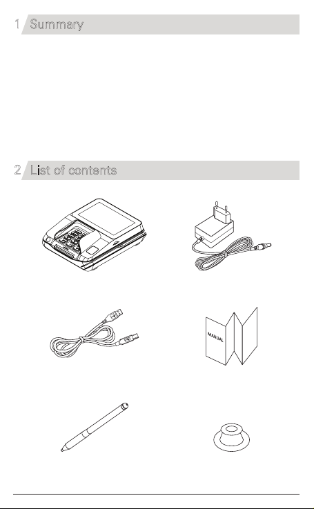
Lynx 9500 User manual


Summary1
2List of contents
LYNX-9500 is the Multi Payment Terminal that supports every payments
service from the contact card, the contactless card, MSR and the Electronic
Signature & PIN to the video file play.
LYNX-9500 ensures the secure payment transaction and the protection of
the cardholder
’
s sensitive information with the newest PCI PTS v5.x
certification. It provides various communication Interfaces and options for
the flexible payment system.
LYNX-9500
1
Manual
Pen Holder
Stylus Pen
Power Adapter
USB Cable

3Product Features
2
16
17
20
No. No.Description Description
1
2
3
4
5
6
7
8
9
10
11
12
13
14
15
16
17
18
19
20
21
LCD Display
Capactive Touch Panel
Keys
IC Card Slot
MSR
RF Antenna area
Camera(Barcode)
Power Switch
Audio Jack
Power Port
Serial Port 2
Serial Port 1
USB Port(B-Type)
USB Port(A-Type)
Ethernet Port
SAM Cover
Port Cover
Privacy Shield
Stylus Pen
Pen Holder(External)
Finger Print
8
9
2
34
5
6
7
18
19
21
1

4Detail Information of Port
3
4.1 ⑩-Ethernet
PIN No.
1
2
Name
TX+
TX-
I/O
O
O
Function
Transmit Data+
Transmit Data-
3
4
RX+
-
I
-
Receive Data+
-
5
6
-
RX-
-
I
-
Receive Data-
7
8
-
-
-
-
-
-
⑩ ⑪ ⑫ ⑬ ⑭ ⑮
LAN
USB
-
A USB
-
B
COM POS
DC 9V

4Detail Information of Port
4
4.3 ⑫-USB-B (Device)
PIN No.
1
2
Name
VUSB
D-
I/O
P
I/O
Function
+5V
Data -
3
4
D+
GND
I/O
P
Data +
Ground
4.2 ⑪-USB-A (Host)
PIN No.
1
2
Name
VUSB
D-
I/O
P
I/O
Function
+5V
Data -
3
4
D+
GND
I/O
P
Data +
Ground

4.4 ⑬-Serial 1
PIN No.
1
2
Name
GND
12V
I/O
P
P
Function
Power
Power
3
4
RXD(IN)
TXD(OUT)
I
O
Serial(RS232 Level)
Serial(RS232 Level)
5
6
GND
DSR(IN)
P
I
Power
Serial(RS232 Level)
7
8
DTR(OUT)
CTS(IN)
O
I
Serial(RS232 Level)
Serial(RS232 Level)
9
10
RTS(OUT)
-
O
-
Serial(RS232 Level)
-
4Detail Information of Port
5

4.5 ⑭-Serial 2
PIN No.
1
2
Name
GND
12V
I/O
P
P
Function
Power
Power
3
4
RXD(IN)
TXD(OUT)
I
O
Serial(RS232 Level)
Serial(RS232 Level)
5
6
GND
-
P
-
Power
-
7
8
-
CTS(IN)
-
I
-
Serial(RS232 Level)
9
10
RTS(OUT)
-
O
-
Serial(RS232 Level)
-
4Detail Information of Port
6
4.6 ⑮-Power (DC9V)
PIN No.
1
2
Name
DC9V
GND
I/O
P
P
Function
+DC9V
Ground

4Detail Information of Port
4.7 SAM Card (Bottom Side)
7
PIN No.
SAM Connector
1
2
Name
VCC
RST
I/O
P
O
Function
SAM Power
SAM Reset
3
5
CLK
GND
O
P
SAM Clock
Ground
7
4,6,8
DATA
-
I/O
NC
SAM Data
Not use
SAM2
SAM4
SAM6
SAM1
SAM3
SAM5
Micro SD Socket

PIN No.
1
2
I/O
I/O
I/O
3
4
O
P
5
6
O
P
7
8
Name
DAT2
CD/DAT3
CMD
VDD
CLK
GND
DAT0
DAT1
I/O
I/O
Function
SD Serial Data2
Card Detect/SD Serial Data3
Command
Power
Clock Output
Ground
SD Serial Data0
SD Serial Data1
4Detail Information of Port
4.8 Micro SD Card Socket
8

5Installation
9
5.1 Adapter and external communication cable connection
- Port Cover should be opened to connect the adapter
cable to supply power and communication cables to
connect with external devices.
- Please close the Port Cover after connection is complete.
5.2 SAM Card
- As shown in below image, open the SAM cover to insert the SAM card.

5Installation
10
5.3 SD Card
- Unlock the SD Card Socket and lift the Socket cover
- Insert the SD card into the socket as shown below,
then lower the socket to lock it.
- Be careful not to raise it above
90 degrees as this may damage
the socket.

5 Installation
5.5 MSR Card
- Insert the card as shown in below image and swipe in any direction.
5.4 IC Card
- IC card should be inserted into IC card slot as shown in below image.
5.6 RF Card
- RF card should be tapped on the upper of LCD as shown in below image.
11

6Recommendations
Caution
- If you observe any abnormal symptom, such as strange smell and
overheating, on first use after purchasing the product,
contact your local dealer immediately.
- Make sure to review the user manual and precautions carefully prior to use.
- In addition, after carefully reviewing the user manual and precautions,
place them in a secure location for future reference when needed.
- Do not modify, take apart, or repair the device.
- Do not use your device at an explosive danger zone.
- In case your device is wet, do not put your device in heaters, microwaves,
or etc to dry- there is a risk of explosion or it can be the cause of malfunction.
- Do not use in places of high temperature and high humidity.
- The following can be the causes of malfunction:
getting wet from the rain, spilling drinks, and taking it in with you
at the sauna (high temp.)
- Please avoid impacts or vibrations. When the device is not in use,
unplug the power cord and place it at a safe place where it won’t drop.
- Do not place your device at a dusty place. Keep your power cord away
from any heating devices. Unplug the power cord when cleaning.
If there are any dusts or residue clean the power cords pins thoroughly.
- Do not paint your device. It can damage your screen or your device’s
exterior. Also, the paint can peel off and it triggers allergies.
If there is allergic reaction, please find medical advice.
- Do not use the sharp metallic material for the touch panel.
- It is recommended to use the provided stylus pen.
12

7Specifications
13
RemarkItem
Processor
O/S
Memory
Display
Contact ICC
Contactless ICC
(13.56MHz)
MSR
1D/2D Scanner
Touch Panel
SOUND
Security Access Module
Key Pad
LED
Peripheral ports
Operating Temperature
Storage Temperature
Power Supply
Dimension
Specification
Cortex-A7 core, 900MHz
Secure Cortex M3 @ 108MHz
Linux 4.1
Flash 256MByte / DDR3 256MByte
5.0 inch, TFT Color 800x480 pixels (LED Backlight)
ISO 7816, 1 IC slot, EMV Level 1 Certified
ISO14443 A,B Card / Mifare / NFC(ISO18092),
ISO15693
ISO 7812 Track 1&2&3 / Bi-directional
CMOS Camera Type
Capacitive Touch Panel
Speaker 1W
Buzzer
Ear-Jack(Stereo, No mic)
6SAMs
15 Key(with Key Backlight)
4 LEDs RF card indicator
RS232#1 X 1
RS232#2 X 1
USB 2.0 Device port (HID)
USB 2.0 Host Port
Ethernet Port (10/100 BaseT)
Micro SD Card Support
0 ºC to +50 ºC
-20 ºC to +60 ºC
DC+9V ±5%, 1.67A.
148.3 mm X 181.5 mm X 47.2 mm
(Exclude Privacy Shield)

Table of contents