MÄDLER Coupling SI Service manual

Date 21/06/2010 Current on the internet at
www.maedler.de
Page 1 from 5
Mounting and operating instructions
Safety clutch SI
Responsible Mädler branches
according to German Post Code Areas: For Switzerland:
PCA 1, 2 and 3 PCA 0, 4 und 5 PCA 6, 7, 8 und 9 Mädler-Norm-Antrieb AG
Subsidiary Subsidiary Headquarter Postbox 74
Mädler GmbH Mädler GmbH Mädler GmbH Güterstr. 6
Brookstieg 16 Bublitzer Str. 21 Tränkestr. 6-8 CH-8245 Feuerthalen
D-22145 Stapelfeld D-40599 Düsseldorf D-70597 Stuttgart Tel. +41 52-647 40 40
Tel. +49 40-60 04 75 10 Tel. +49 211-97 47 1 0 Tel. +49 711-7 20 95 0 Fax +41 52-647 40 41
Fax +49 40-60 04 75 33 Fax +49 211-97 47 1 33 Fax +49 711-7 20 95 33
hamburg@maedler.de duesseldorf@maedler.de stuttgart@maedler.de
www.maedler.ch

Date 21/06/2010 Current on the internet at
www.maedler.de
Page 2 from 5
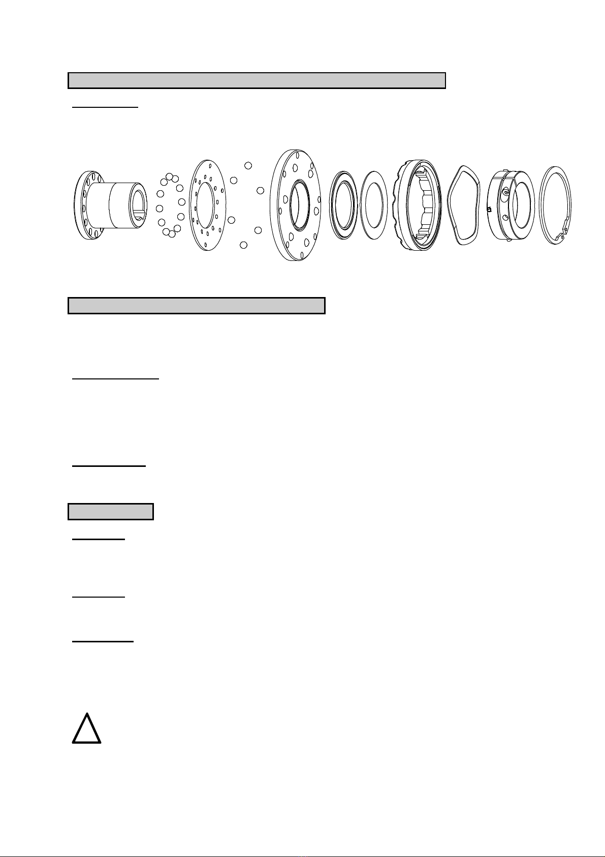
The Coupling SI is an overload system with positive locking. It protects the following components
against destruction.
It re-engages after 30°each into the following lock-in position in case of an overload.
Gen
eral Hints
Please read through these mounting instructions carefully before you set the coupling into operation.
Please pay special attention to the safety instructions!
The mounting instructions are part of your product. Please keep them carefully and close to the
coupling.
Safety and Advice Hints
STOP
D A N G E R ! Danger of injury to persons.
!
C A U T I O N ! Damages on the machine possible.
A T T E N T I O N ! Pointing to important items.
General Hints to Dange
r
STOP
D A N G E R !
With assembly, operation and maintenance of the coupling it has to be made sure
that the entire drive train is secured against unintentional engagement. You can be
seriously hurt by rotating parts. Please make absolutely sure to read through and
observe the following safety instructions.
•All operations on and with the coupling have to be performed taking into account "safety first".
•Please make sure to disengage the drive unit and the power packs in service before you perform
your work.
•Secure the drive unit against unintentional engagement, e. g. by providing hints at the place of
engagement or removing the fuse for current supply.
•Do not touch the operation area of the coupling as long as it is in operation.
•Please secure the coupling against unintentional touch. Please arrange for the corresponding
protection devices and caps.
Proper Use
You may only assemble, operate and maintain the coupling if you
•have carefully read through the mounting instructions and understood them
•and if you are authorised and have proper skills
The coupling may only be used in accordance with the technical data. Unauthorized modifications on
the coupling design are not admissible. We do not take any warranty for resulting damages. To further
develop the product we reserve the right for technical modifications.
The Coupling SI described in here corresponds to the technical status at the time of printing of these
mounting instructions.
The Coupling SI overload system is delivered in assembled condition.

Date 21/06/2010 Current on the internet at
www.maedler.de
Page 3 from 5
Components Coupling SI
Component
Quantity
Nomination
Component
Quantity
Nomination
1 1 hub 9 1 shaft lock washer
2 1 disk spring 10 1 circlip
3 1 flange ring 11 1 set screw DIN 912
4 1 shifting ring 12 1 grub screw DIN 916
5 1 setting nut 13 3 clamping sleeve DIN 7346
6 1 slide bush 14 6 round head grooved pin
7 1 axial needle spider 15 18 ball DIN 5401
8 1 axial disk
picture 1: Coupling SI
General mounting instructions
•Please make sure the perfect technical condition of the Coupling SI overload system.
•Before assembly and operation please check whether it is necessary to clean the components.
•Lubricate the balls (e. g. Klüber-Microlube GL 263).
•Please only use original components.
Adju
stment of a higher torque of engagement
•Fix the hub against twisting.
•Unscrew the set screw in the setting nut.
•Rotate the setting nut clockwise with a sickle spanner acc. to the 12 partition in the shifting ring.
•An axial thrust of the shifting ring corresponds to a twisting angle of 30°(see table of torque of
engagement).
•When the desired torque of engagement is adjusted, fix the setting nut by screwing down the set
screw on the threaded portion of the hub.
Adjustment of a lower torque of engagement
•Fix the hub against twisting.
•Unscrew the set screw in the setting nut.
•Rotate the setting nut anticlockwise with a sickle spanner acc. to the 12 partition in the shifting ring.
•An axial thrust of the shifting ring corresponds to a twisting angle of 30°(see table of torque of
engagement).
•Count the number of axial thrusts; one axial thrust = twisting angle of 30°.
•When the desired torque of engagement is adjusted, fix the setting nut by screwing down the set
screw on the threaded portion of the hub

Date 21/06/2010 Current on the internet at
www.maedler.de
Page 4 from 5
Table
of torque of engagement [Nm]
The Coupling SI overload system is adjusted with the torques of engagement indicated in the table, if
the customer does not indicate any other value.
!
C A U T I O N !
The Coupling SI overload system must not exceed the max. torque of engagement!
Twisting angle 612 720 00 612 725 00 612 735 00 612 750 00
setting nut spring
TD1
spring
TD2
spring
TD1
spring
TD2
spring
TD1
spring
TD2
spring
TD1
spring
TD2
30° 5 10 15 50
60° 7 20 25 57
90° 8 15 23 28 65
120° 9 17 25 32 73
150° 11 20 29 35 80
180° 13 23 33 46 38 88
210° 15 25 37 52 40 78 95
240° 17 27 41 58 45 86 100
270° 18 29 45 64 49 93 110
300° 20 30 49 70 53 100 118
330° 52 76 57 108 126 175
360° 55 82 61 115 134 188
390° 58 86 66 122 142 200
420° 60 90 71 129 150 212
450° 74 136 157 225
480° 77 143 165 237
510° 80 150 172 250
540° 180 262
570° 275
600° 288
630° 300
preadjusted torque of engagement
Adjustment
of the torque of engagement after the disassembly
Please observe the following instructions in case of the assembly (see picture 2):
•Assemble the Coupling SI overload system in the order as shown in the explosion drawing.
•Assemble the balls with the help of a lubricant (e. g. Klüber-Microlube GL 263). Make sure that balls
fit properly.
•The elements shifting ring, ondular washer and safety ring do not have to be assembled yet.
•Tighten the part of the setting nut without thread in the direction of the thread of the hub, tighten the
setting nut onto the thread of the hub until it is in contact with the surface of the flange ring.
•Move the shifting ring onto the setting nut. Make sure that the shifting ring nuts fit properly on the
grooved drive studs (turn the setting nut into the right position).
•Insert the ondular washer into the recess of the shifting ring.
•Insert the safety ring into the keyway of the setting nut (make sure a proper fit).
•Turn the setting nut clockwise by one pitch (30°) by means of a sickle spanner. A revolution of 30°
corresponds to one axial thrust of the shifting ring.
•With this assembled condition the minimum slipping torque (see table of torque of engagement) of
each size is achieved.
•By turning the setting nut clockwise you can set a higher torque acc. to the pitch.

Date 21/06/2010 Current on the internet at
www.maedler.de
Page 5 from 5
Adjustment of the torque of engagement after the disassembly
Continuation:
•When the requested slipping torque is set, fix the setting nut by tightening the set screw
on the threaded portion of the hub.
picture 2
Assembly feather keyway or clamping set
A T T E N T I O N !
Please check the bore, shaft, keyway and feather key before the assembly
concerning their dimensional accuracy.
Feather keyway:
For the axial fixing of the Coupling SI overload system with cylindrical finish bore (standard:
ISO fit - H7) and feather keyway (standard: DIN 6885, page 1 - JS9), there are the following
possibilities.
1.
Tighten the grub screw on the feather key or the shaft.
2.
Secure the hub with an end plate and a screw. The grub screw must be removed.
Clamping set:
Please ask for the special mounting instruction for the respective clamping set.
Please consider the assembly situation.
Limit switch
Operation
The axial thrust of the shifting ring arising in the event of overload operates a mechanical
limit switch or an inductive sensor. Consequently a control operation is performed to
disengage the drive.
Assembly
The sensor has to be mounted in a solid device in order to ensure a smooth operation. The
sensor should be protected against dirt and potential mechanical disorders.
Adjustment
When the overload coupling slips, the shifting ring makes an axial thrust of about 2 mm. The
sensor or limit switch, respectively, has to be mounted within this shifting range. In order to
adapt the mechanical limit switch and the shifting process to the machine, the limit switch
has to be adjusted accordingly. For that purpose the shifting process can be regulated after
opening the cover plate on the tappet.
!
C A U T I O N !
Before delivery of the machine please make absolutely sure to check the operation
of the limit switch. Please also note the operating instructions for the sensor or
limit switch, respectively. The axial thrust of the hub must not be obstructed by
other components.
Table of contents
Other MÄDLER Industrial Equipment manuals