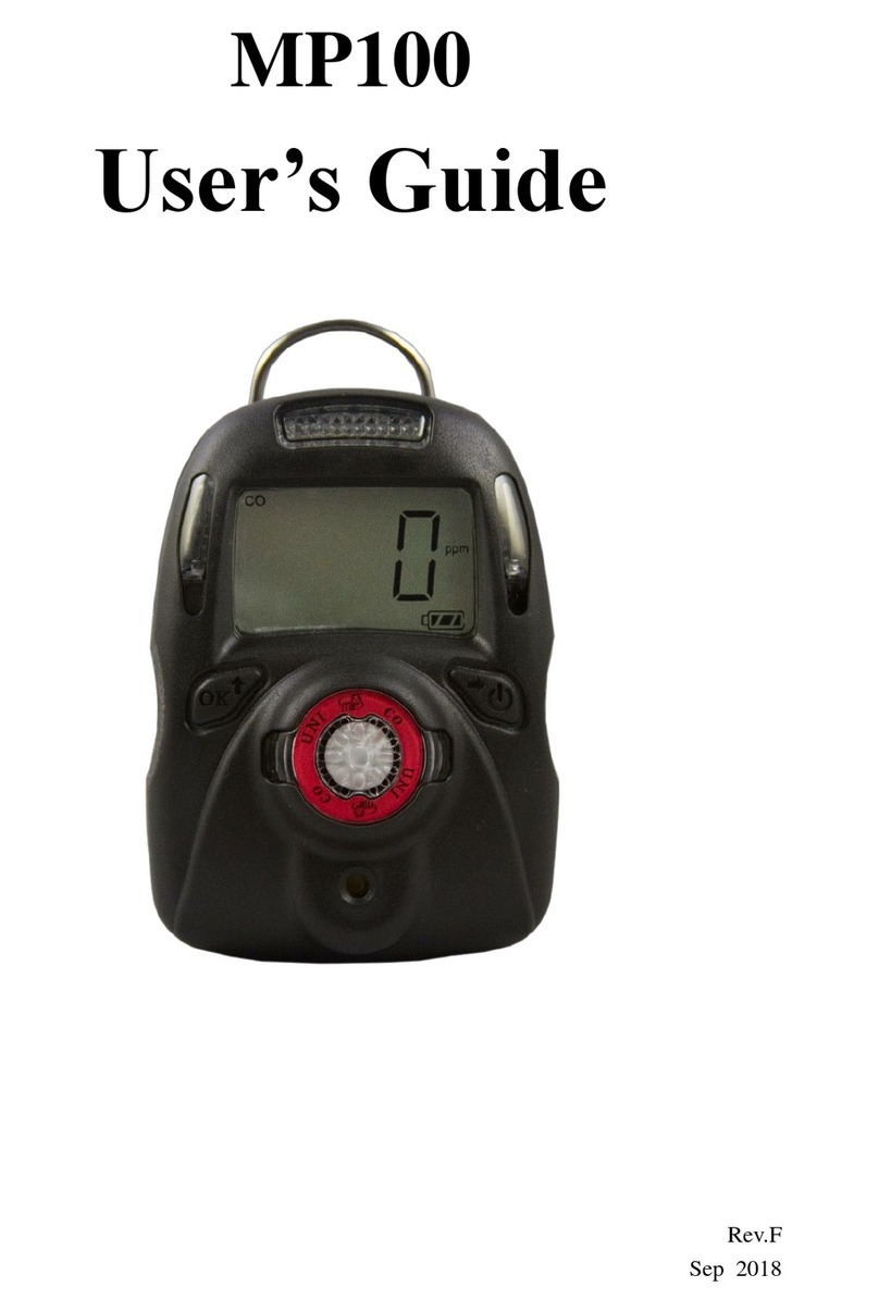
M-Power UNI MP100 Series User manual

Warning
•Never operate the monitor when the cover is removed.
•Remove the monitor cover and battery only in area known
as non-hazardous.
•Use only mPower’s lithium battery part number
1.17.02.0002 (3.6 V, 2700 mAH, AA size).
•This instrument has not been tested in an explosive gas/air
atmosphere having an oxygen concentration greater than
21%.
•Substitution of components will impair suitability for
intrinsic safety and void warranty.
•It is recommended to bump test with a known
concentration gas to confirm the instrument is functioning
properly before use.
•Before use, ensure that the ESD film on the display is not
damaged or peeling.
Avertissement
•N'utilisez jamais le moniteur lorsque le couvercle est enlevé.
•Retirer le couvercle du moniteur et la batterie uniquement
dans une zone connue comme non dangereuse.
•Utilisez uniquement le numéro de pièce de la batterie au
lithium mPower 1.17.02.0002.
•Cet instrument n'a pas été testé dans une atmosphère
explosive gaz / air ayant une concentration en oxygène
supérieure à 21%.
•La substitution de composants compromettra l'aptitude à la
sécurité intrinsèque et annulera la garantie.
•Il est recommandé de tester avec un gaz de concentration c
onnu pour confirmer que l'instrument fonctionne correctem
ent avant de l'utiliser.
•Avant de l’utiliser, assurez-vous que le film ESD sur
l'écran n'est pas endommagé ou épluché.
Read Before Operating
The User’s Guide must be carefully read by all
individuals who have or will have the responsibility of
using, maintaining, or servicing this product. The
product will perform as designed only if it is used,
maintained, and serviced in accordance with the
manufacturer’s instructions.
User Interface
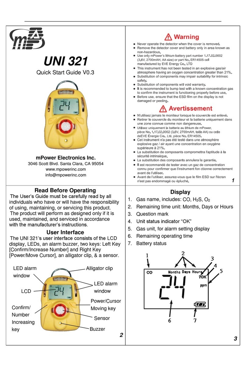
The UNI’s user interface consists of the LCD
display, LEDs, an alarm buzzer, two keys: Left Key
[Confirm/Number increasing] and Right Key
[Power/Cursor moving], an alligator clip, and a
chemical sensor.
Display Detail
1. Gas name, including CO, H2S, SO2, or O2
2. Question mark (perform operation?)
3. OK status indicator (or accept number entry)
4. Concentration unit, e.g. ppm, %, mg/m3, etc.
5. Battery charge status
6. Alarm type indicator
7. Zero in progress indicator
8. Calibration in progress indicator
9. Concentration or other numerical value
UNI
MP100 Series
Quick Start Guide
PN:M001-4029-000 v1.3
2
Alligator clip
Battery
status
Power/Cursor
moving key
LED alarm
window
LCD
Display
Confirm/
Number
increasing key
Sensor with
ID on label
Buzzer
4
3

Turning the Unit On
Press and hold the Right Key for 4 seconds, until
the LCD displays “On”, the buzzer beeps, and the
green LED is on. The unit enters a warm up and self-
test sequence, shows the firmware version, e.g.
"VER","1.0.0.0" and the programmed alarm limits,
STEL, TWA, etc.
Note: Some units may need several minutes to an
hour to stabilize and should be re-zeroed at that time.
Turning the Unit Off
In normal display mode, press and hold the Right
Key for a 5-sec. count down until the unit powers off.
Normal mode
In normal mode, the gas concentration displayed on
the LCD continuously and the unit alarms if a pre-set
limit is exceeded. The user can check various other
values like STEL, TWA, PEAK, and (for O2) MIN by
pressing the Right Key. Alarm events are also shown.
Enter Configuration Mode
Press and hold the Left and Right keys together for
3 seconds, until “PWD” is displayed, prompting
password entry. To input the password, use the Left
Key to increase the number, and the Right Key to
move the cursor. After all four digits are entered, the
cursor will move to “OK”. Use the Left Key to
accept and enter Config Mode.
Configuration Mode Menu
In Config Mode the user can do calibrations and
change various operating parameters:
⚫AiR, SPAN: Zero or Span calibration,
⚫BUMP: Bump test
⚫SET HIGH\LOW\STEL\TWA alarm limits
⚫SET Cal: Change span value
⚫CAL INTV, BUMP INTV span or bump interval
⚫SET UniT: Change concentration unit
⚫Vib SET: Vibrator enable/disable
⚫P-on Zero SET: Power on zero enable/disable
⚫FAST SET: Fast power on enable/disable
⚫RST cF9: Reset configuration to default values
⚫EXIT: Exit Config Mode
In Config Mode, in general, use the Left Key to
increase a number or confirm, and use the Right Key
to move the cursor or move to the next
programming item.
Exit Configuration Mode
Scroll to “EXIT?” and press the Left Key to exit
Config Mode and return to Normal Mode.
Daily Self-Test
Press the Left Key to confirm that the LEDs
flash, the buzzer beeps and the unit vibrates if
programmed to do so.
Alarm Limits
To adjust an alarm limit, enter Config Mode and
scroll to the desired alarm: SET HIGH\LOW\STEL\TWA?.
⚫Press Left to display the alarm value with the first
digit flashing
⚫Use Left to move to the desired flashing digit
⚫Use Right to increase the value and cycle 0-9.
⚫When finished, scroll Right to OK and press Left
to save and exit.
Zero (Fresh Air) Calibration
Zero calibration sets the base line for the sensor
and is done in fresh air or other clean air source. Enter
Config Mode and “AiR?”displays as the first menu
item. Press the Left key to start the15-second zero
calibration count-down, after which a “pass” or “fail”
result will be displayed.
To abort, press the Right key at any time during the
15-second count, and “AbRT”displays to confirm.
Span Calibration (continued)
Span calibration uses a known concentration gas
to determine the response of the sensor to the gas.
1. Attach the Calibration Adapter over the inlet
port on the front of unit by pressing it into place.
Use a fixed-flow regulator
with a flowrate of preferably
about 0.3 to 0.5 LPM. Higher flowrates can be
used if necessary, but not lower. For reactive gases,
e.g., hydrogen chloride, hydrogen fluoride, ozone,
chlorine dioxide, phosphine, ammonia and ethylene
oxide, be sure to use Teflon tubing connections.
2. Enter Config Mode and scroll to “SPAN?”
3. Start the gas flow, and press the Left key to
start the calibration countdown. The default count
time is 60 seconds, but some sensors will go longer.
4. When finished, a “pass” or “fail” result will be
displayed. Turn off the gas supply, remove the
calibration adapter, and exit to Normal Mode.
5. To abort at any time during the count-down,
press the Right Key and “AbRT”is displayed.
Buzzer
5
6
8
7
8

Maintenance and Service
If used in high-dust environments, replace the inlet
filter regularly. Battery and sensor can be replaced as
needed. For other maintenance, contact mPower’s
service department or refer to the full User Manual.
Proper Product Disposal
at The End Of Life
The Waste Electrical and
Electronic Equipment
(WEEE) directive
(2002/96/EC) is intended to
promote recycling of
electrical and electronic
equipment and their
components at the end of life.
This symbol (crossed-out wheeled bin) indicates
separate collection of waste electrical and electronic
equipment in the EU countries. This product may
contain one or more nickel-metal hydride (NiMH),
lithium-ion, or alkaline batteries. Specific battery
information is given in this user guide. Batteries
must be recycled or disposed of properly. At the end
of its life, this product must undergo separate
collection and recycling from general or household
waste. Please use the return and collection system
available in your country for the disposal of this
product.
9
10
Other M-Power Gas Detector manuals
Popular Gas Detector manuals by other brands
STATUS SCIENTIFIC CONTROLS
STATUS SCIENTIFIC CONTROLS FGD10A Installation, Commissioning & Routine Gas Testing Manual

FORENSICS DETECTORS
FORENSICS DETECTORS FD-CO2000 quick start guide
S&S Northern
S&S Northern MERLIN CO DETECTOR X Installation operation & maintenance
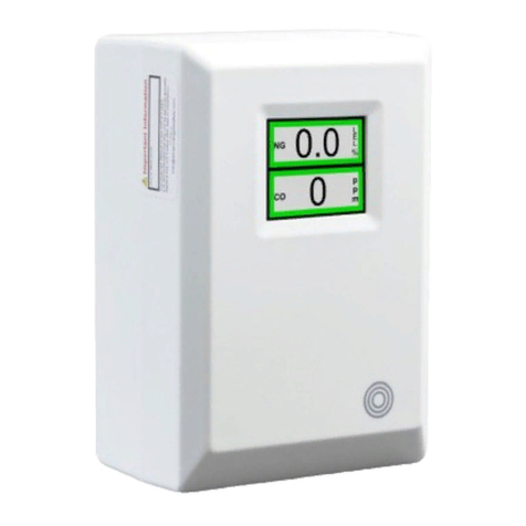
AGS
AGS Mini Merlin LPGCO user guide
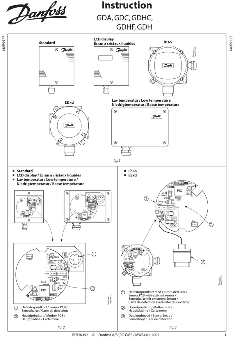
Danfoss
Danfoss GDC Instruction
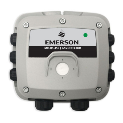
Emerson
Emerson MRLDS-450 quick start guide
