BEFORE USE ....
Thank you for choosing M-System. Before use, please check
contents of the package you received as outlined below.
If you have any problems or questions with the product,
please contact M-System’s Sales Office or representatives.
■PACKAGE INCLUDES:
Signal conditioner
(body + base socket + input resistor)..................................(1)
Input resistor is provided only with current input type.
■MODEL NO.
Confirm Model No. marking on the product to be exactly
what you ordered.
■INSTRUCTION MANUAL
This manual describes necessary points of caution when you
use this product, including installation, connection, hard-
ware setting, operation of the Programming Unit (model:
PU-2x)* specific to this model and basic maintenance pro-
cedures.
This unit is factory adjusted and calibrated according to the
Ordering Information included in the product package. If
you don’t need to change the pre-adjusted setting, you can
skip the sections on hardware setting and calibration and
Software Setting in this manual.
*When you need to change software settings, please refer to
the Operation Manual for Model PU-2x (EM-9255), Section B:
(B-1) Introduction, (B-2) General Operation Description, (B-3)
Operation Flow chart for general information.
POINTS OF CAUTION
■POWER INPUT RATING & OPERATIONAL RANGE
• Locate the power input rating marked on the product and
confirm its operational range as indicated below:
100 – 240V AC rating: 85 – 264V, 47 – 66 Hz,
approx. 3.2VA at 100V AC
approx. 5.1VA at 200V AC
approx. 6.9VA at 264V AC
12 and 24V DC ratings: Rating ±10%, approx. 2.5W
110V DC rating: 85 – 150V DC, approx. 2.5W
■GENERAL PRECAUTIONS
• Before you remove the unit from its base socket or mount
it, turn off the power supply and input signal for safety.
■ENVIRONMENT
• Indoor use.
• When heavy dust or metal particles are present in the
air, install the unit inside proper housing with sufficient
ventilation.
• Do not install the unit where it is subjected to continuous
vibration. Do not subject the unit to physical impact.
• Environmental temperature must be within -5 to +55°C
(23 to 131°F) with relative humidity within 30 to 90% RH
in order to ensure adequate life span and operation.
■WIRING
• Do not install cables close to noise sources (relay drive
cable, high frequency line, etc.).
• Do not bind these cables together with those in which
noises are present. Do not install them in the same duct.
■AND ....
• The unit is designed to function as soon as power is sup-
plied, however, a warm up for 10 minutes is required for
satisfying complete performance described in the data
sheet.
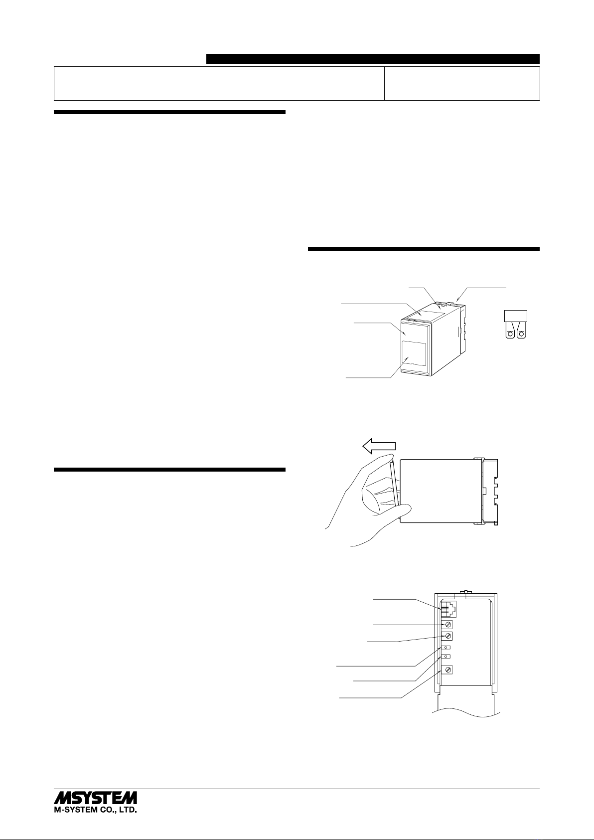
COMPONENT IDENTIFICATION
Body Base Socket
Connection Diagram
Front Cover
Specifications
Input Resistor
■HOW TO OPEN THE FRONT COVER:
Hang your finger on the hook at the top of the front cover
and pull.
The shape of base socket may be different
for some models.
■FRONT PANEL CONFIGURATION
Output Voltage Adj.*
Output Monitor LED
Modular Jack
Zero Adj.
Span Adj.
Monitor LED (no function)
*only for voltage pulse output
Note: The output voltage is already adjusted according to the
ordering information sheet. Do NOT change the Output
Voltage.
DC/FREQUENCY CONVERTER
(eld-programmable) MODEL JAPD2
5-2-55, Minamitsumori, Nishinari-ku, Osaka 557-0063 JAPAN
EM-1571 Rev.2 P. 1 / 4
INSTRUCTION MANUAL


