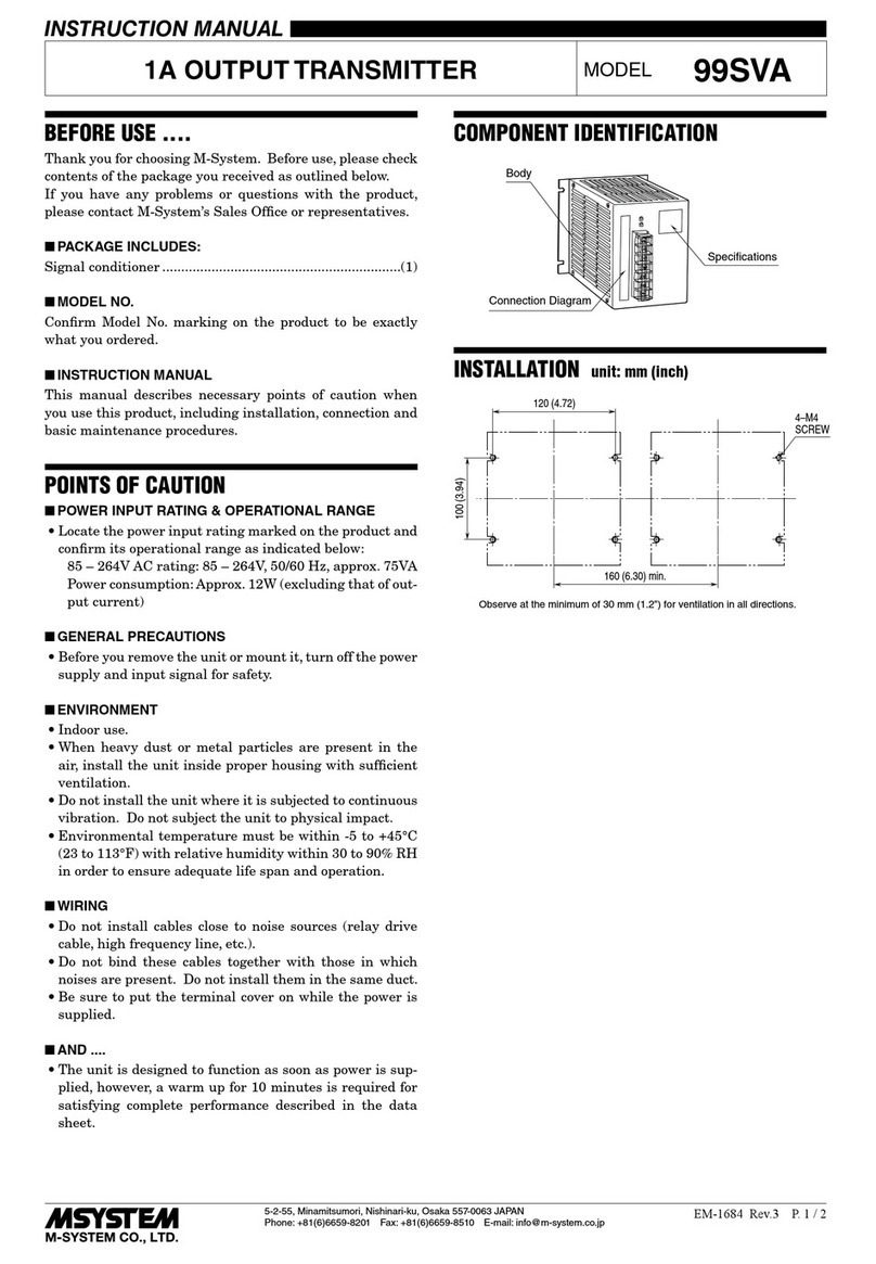
4) Make wiring as shown below. Turn power supply on, and
warm up for about 10 minutes.
VOLTAGE
GENERATOR
6TS1
POWER
24V DC
+15
234
6
–
+–RL
RL: STANDARD LOAD (250Ω ±0.1%)
DIGITAL VOLTMETER: 4 DIGITS
CJMTEMP. SENSOR
• Requirements for Calibration Equipment
Voltage Generator: Must be able to generate mV with
temperature sensor calibration func-
tion.
Accuracy ±0.02% or better required.
Temperature sensor: Semiconductor sensor for cold junc-
tion compensation. Accuracy ±0.3°C
or better required in combination
with the Voltage Generator.
Digital Voltmeter: 4-digit meter.
Accuracy ±0.01% or better required.
All calibration instruments must meet or exceed the above
mentioned specifications. M-System does not guarantee
this product’s stated accuracies and specifications if these
calibration requirements are not met.
■THERMOCOUPLE TYPE SELECTION
1) Adjust SW1 (rotary code switch) to an appropriate po-
sition for customer’s thermocouple type. Positions are
shown in the illustration below.
3
SS-10
•6
51 42
1 : PR, R, S thermocouples
2 : K (CA) thermocouple
3 : E (CRC) thermocouple
4 : J (IC) thermocouple
5 : T (CC) thermocouple
6 : B thermocouple
■INPUT BIAS ADJUSTMENT (0% temperature)
Check first electromotive force (mV) for 0% (and 100%) tem-
perature in Thermocouple Reference Table.
1) Close across the front terminal 2 – 3 and remove tem-
perature sensor connected to voltage generator as in the
above illustration. (Canceling cold junction compensa-
tion)
2) Connect a digital voltmeter across the front terminal 2
(–) and TP1 (+).
3) With minimum (0%) input, adjust SW2 to appropriate po-
sitions – nearest to desired value – according to Table 1
[INPUT BIAS SELECTION TABLE], and adjust output
reading to 0 ±0.002V with VR5 (zero-coarse adjustment).
4) With minimum (0%) input, adjust output to 0 ±0.05%
with VR1 (zero-fine adjustment).
■INPUT RANGE ADJUSTMENT (100% temperature)
5) With maximum (100%) input, adjust SW3 to appropriate
positions according to Table 4 to Table 6 [INPUT RANGE
SELECTION TABLE], and adjust output to 100 ±0.05%
with VR4 (span-coarse adjustment) and VR2 (span-fine
adjustment).
6) With minimum (0%) input, check that input is 0 ±0.05%.
When the ZERO point is changed, repeat the procedure
2) to 5).
■COLD JUNCTION COMPENSATION ADJUSTMENT
7) Connect temperature sensor to the voltage generator
again and remove shortcircuit across the terminal 2 – 3.
8) With minimum (0%) input, adjust output reading to 0%
with VR3.
■OUTPUT ZERO & SPAN ADJUSTMENT
1) ZERO: Apply 0% input and adjust output to 0% with the
VR1.
2) SPAN: Apply 100% input and adjust output to 100% with
the VR2.
3) Check ZERO adjustment again with 0% input.
4) When ZERO value is changed, repeat the above proce-
dure 1) – 3).
MAINTENANCE
Regular calibration procedure is explained below:
■CALIBRATION
Warm up the unit for at least 10 minutes. Apply 0%, 25%,
50%, 75% and 100% input signal. Check that the output
signal for the respective input signal remains within accu-
racy described in the data sheet. When the output is out of
tolerance, recalibrate the unit according to the “ADJUST-
MENT PROCEDURE” explained earlier.
LIGHTNING SURGE PROTECTION
M-System offers a series of lightning surge protector for
protection against induced lightning surges. Please contact
M-System to choose appropriate models.
6TS1
5-2-55, Minamitsumori, Nishinari-ku, Osaka 557-0063 JAPAN
Phone: +81(6)6659-8201 Fax: +81(6)6659-8510 E-mail: info@m-system.co.jp
EM-4211 Rev.7 P. 3 / 4

