M-tech QTAC 75UHP User manual

Page | 1
75UHP
Owner’s Manual
QTAC is a division of MTECH, Inc.

Page | 2
A THANK YOU FROM THE PRESIDENT
Dear Customer,
Thank you very much for purchasing a QTAC product. We know that a purchasing
decision like this requires careful consideration, and we appreciate you selecting QTAC
for your needs.
We are passionate about offering products that provide top-level fire protection, and we
let that passion guide us in all the QTAC products we develop and manufacture here at
our facility in Northern California. We hope that after getting to know your QTAC
product, you feel that same passion.
Sincerely,
Jason Black
President

Page | 3
TABLE OF CONTENTS
A Thank You From The President...................................................................................2
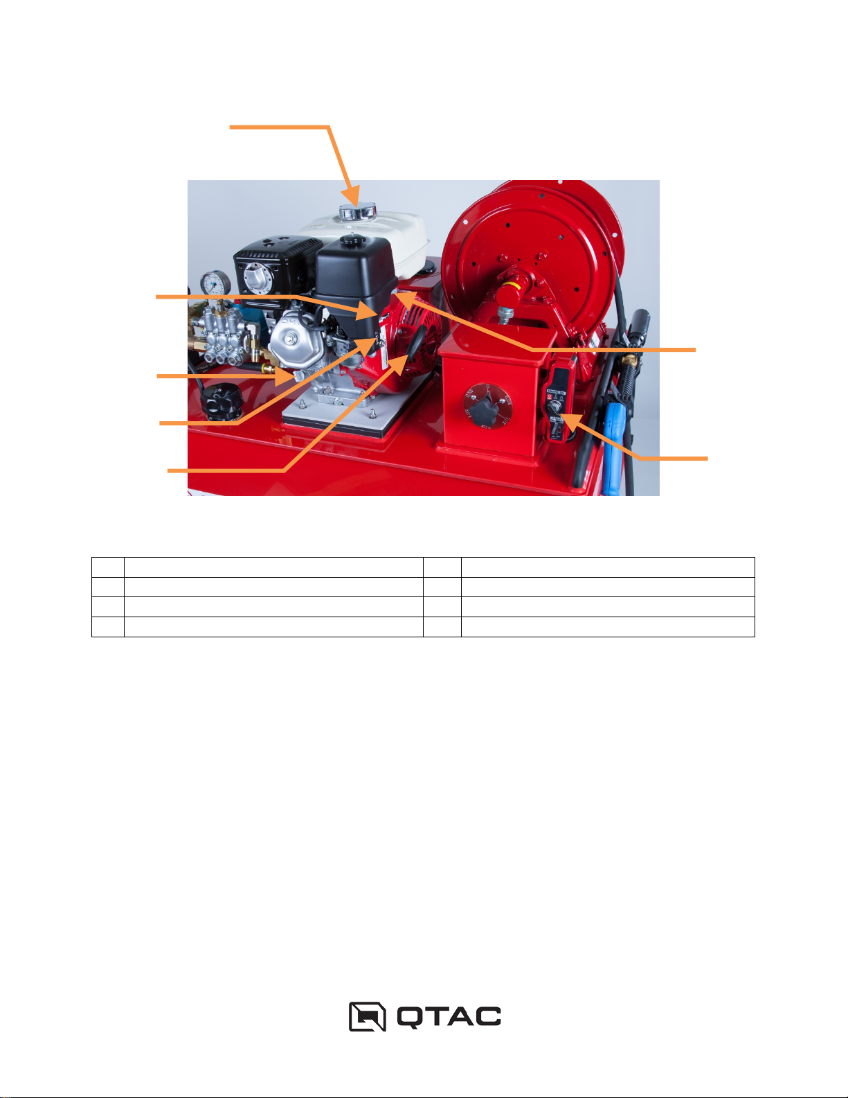
Getting To Know Your QTAC..........................................................................................5
Transporting Your QTAC.................................................................................................9
Gross Vehicle Weight Rating.......................................................................................9
General QTAC Mounting and Fastening......................................................................9
Special Precautions For Carrying a QTAC On Ride-On ATVs Or Side-By-Side UTVs
...................................................................................................................................10
Operating Your QTAC...................................................................................................12
Before Starting Up Your QTAC..................................................................................12
Starting Up Your QTAC.............................................................................................12
Breaking Your QTAC In.............................................................................................13
Running Your QTAC..................................................................................................13
Stopping Your QTAC.................................................................................................14
Storing Your QTAC .......................................................................................................15
General Storage........................................................................................................15
Special QTAC Operation...............................................................................................16
Applying Foam With Your QTAC...............................................................................16
Servicing Your QTAC....................................................................................................17
Cleaning Your QTAC.................................................................................................17
Routine QTAC Maintenance......................................................................................17

Page | 4
Troubleshooting Your QTAC.........................................................................................18
The Pump Engine Will Not Start................................................................................18
The Pump Will Not Build Water Pressure..................................................................18
Water Will Not Discharge From The Discharge Hose................................................19
Technical Specifications................................................................................................20
Additional References...................................................................................................21
Warranty........................................................................................................................22

Page | 5
GETTING TO KNOW YOUR QTAC
Figure 1– Water Tank Components
1
Water Tank Vent
8
Water Tank Site Gauge
2
Water Tank
9
Water Tank Grab Handle
3
Water Tank Drain Port
10
Pump Intake Strainer
4
Discharge Hose Reel & Hose
11
Water Tank Mounting Flange
5
Foam Reservoir Fill Port & Vent
12
Foam Proportioner Adjustment Knob
6
Foam Shut-Off Valve and Strainer
13
Engine Ignition Switch
7
Water Tank Fill Port
14
Discharge Gun
2
8
7
6
1
5
11
13
4
9
10
14
3
12

Page | 6
Figure 2- Pump Components
1
Pressure Regulator
3
Pump Return Hose
2
Pump Drain Cock
4
Pump Pressure Gauge
4
2
3
1

Page | 7
Figure 3- Pump Engine Components
1
Fuel Fill
5
Recoil Starter Handle
2
Carburetor Choke
6
Engine Switch/Electric Start
3
Oil Fill
7
Engine Throttle
4
Fuel Shut-Off Valve
7
3
2
1
5
4
6

Page | 8
Figure 4– Discharge Gun Components showing (a) Aerating Position and (b) Non-
Aerating Position
1
Quick Disconnect
3
Aeration Lever
2
Trigger
4
Nozzle
1
2
3
4
(b)
(a)

Page | 9
TRANSPORTING YOUR QTAC
Gross Vehicle Weight Rating
•Ensure that the gross vehicle weight rating (GVWR) of the QTAC carrying vehicle
is sufficient to support your QTAC unit and a full tank of water, plus any
equipment, fluids and personnel that you may wish to carry. Alternatively, you
can reduce the volume of water in your QTAC to maintain a GVWR under the
limit of your vehicle.
General QTAC Mounting and Fastening
•Ensure that your QTAC unit is secured to the carrying vehicle. Two main
mounting approaches are available for your QTAC unit:
oStrapping the QTAC down just inboard of the grab rails located at the top
of the water tank (see Figure 5).
oMounting the QTAC at the flanges (see Figure 1and Figure 5), located at
the bottom of the water tank (the flanges have been machined to accept a
variety of mounting hardware options).
For both mounting approaches, ensure that the bottom of the QTAC (including
the mounting flanges) abuts a firm, flat surface or rack. Avoid significant
leveraging of the mounting flanges. See Figure 5for examples of proper and
improper mounting surfaces.

Page | 10
Figure 5 – Tie-down routing and bolting locations
Special Precautions For Carrying a QTAC On Ride-On ATVs Or Side-By-
Side UTVs
•Ensure that the area to which you are securing your QTAC is an approved
loading area for your ATV or UTV.
•Ensure that the weight of your QTAC does not exceed the maximum
recommended weight of the ATV or UTV loading area to which you are securing
your QTAC.
IMPROPER
MOUNTING
SURFACE!
PROPER
MOUNTING
SURFACE
TIE-DOWN
CONFIGURATION

Page | 11
•The additional weight of your QTAC may result in a.) Poor steering response
and/or b.) An increased inclination for the wheels of the ATV or UTV to lift off the
ground. Therefore, the operator should spend some time operating the vehicle in
a safe area (e.g. wide and flat) once the QTAC has been properly secured and
loaded to ensure the vehicle operates in a safe manner. If the vehicle does not
operate in a safe manner, immediately recheck the GVWR calculations to ensure
that the QTAC unit is not overloading your vehicle. If the unsafe operation cannot
be corrected, do not carry your QTAC in this fashion.
•When carrying your QTAC unit on the rear rack of an ATV or in the bed of a UTV,
avoid steep side slopes. If an uphill must be traversed, it is recommend that you
back your ATV or UTV up the uphill to avoid the front wheels lifting on the uphill.

Page | 12
OPERATING YOUR QTAC
Before Starting Up Your QTAC
•Always wear appropriate eye, ear, and body protection when operating your
QTAC unit.
•Ensure that your QTAC has sufficient water in the water tank prior to operation.
The water level can be checked by viewing the water tank site gauge located on
the side of the water tank (see Figure 1). If the water tank is low on water, open
the water tank fill port (see Figure 1) and fill the water tank with water.
•Check the pump engine fuel and the pump engine and pump oil levels (see
Figure 2and Figure 3). As needed, fill the pump engine and pump with fuel and
oil as specified in the engine and pump manuals that came with your QTAC. For
more information, see the CAT 5CP Pump Operation Manual and the Honda
GX270 Owner’s Manual.
Starting Up Your QTAC
1. As appropriate, set the carburetor choke on the pump engine (see Figure 3). If
the engine is cold, choke will typically be needed. As a general rule, colder days
require more choke than warmer days.
2. Ensure that the fuel shut-off valve is in the “ON” position (see Figure 3).
3. Ensure that the engine switch is set to the “ON” position (see Figure 3).
4. Pull and hold the trigger on the discharge gun (see Figure 4) to relieve back
pressure on the pump. Alternatively, the pump pressure regulator (see Figure 2)
can be fully backed out to relieve the pump back pressure (in which case, the
discharge gun does not need to be open to relieve back pressure).
WARNING:Always be cognizant where the discharge gun is pointing when the
trigger is pulled! The UHP pumping system generates up to 1,200 PSI in

Page | 13
pressure which is more than enough to cause serious injury to nearby people,
animals, and other objects.
5. If using the electric start, turn the key to the “Start” position on engine
switch/electrical start (see Figure 1) until the engine begins to run. Alternatively,
pull the recoil starter handle until the engine begins to run (see Figure 3).
6. As soon as the engine begins to run, the trigger on the discharge gun can be
released (if open). Alternatively, if the pump pressure regulator has been fully
backed out, begin to increase the pressure with the pressure regulator until the
regulator is fully turned in to the maximum operating pressure.
7. As the engine warms, decrease the choke setting as necessary.
8. Increase the throttle position to approximately a third of the wide open throttle
position (see Figure 3).
9. In non-emergency cases, it is best to allow the pump engine and pump a warm-
up period to reach normal operating temperature prior to any wide open throttle
operation.
Breaking Your QTAC In
•Your QTAC has been tuned and tested at the factory prior to shipment, and
requires no further break in or setup. For more information on break in of the
pump and pump engine, see the CAT 5CP Pump Binder and the Honda GX270
Owner’s Manual.
Running Your QTAC
•The pump is cooled by the water in the pumping system. Therefore, water must
be available for the pump via the water tank at all times when running your
QTAC. Running the pump without water can result in severe pump damage.
•Your QTAC is equipped with a closed-loop water recirculation system operating
between the pump and the water tank. Due to this design, you can keep the

Page | 14
delivery nozzle closed with the pump engine running (assuming sufficient water
exists within the water tank for recirculation) – no damage to the pump will occur.
•In addition to the trigger, the discharge gun has a two-position aeration lever (see
Figure 4). When using water only, keep the aeration lever in the non-aerating
position.
Stopping Your QTAC
1. Release the trigger on the discharge gun (see Figure 4).
2. Decrease the throttle on the pump engine to the idle position (see Figure 3).
3. Set the engine switch to the “OFF” position (see Figure 3).

Page | 15
STORING YOUR QTAC
General Storage
•Drain the fuel from the pump engine carburetor and fuel tank. See the Honda
GX270 Owner’s Manual for additional details.
•Drain any water from the water tank by opening the water tank drain port (see
Figure 1).
•Drain the water from the pump. See the CAT 5CP Binder for additional details.
NOTE: If your QTAC will be subjected to below freezing temperatures, ensure
that all water is drained from the water tank and pumping system. If you would
like to keep water in your QTAC in below freezing temperatures, make sure to
add an appropriate amount of antifreeze to the water to prevent the formation of
ice.

Page | 16
SPECIAL QTAC OPERATION
Applying Foam With Your QTAC
1. Ensure that the foam shut-off valve (see Figure 1) is in the open position (the
handle of the valve will be parallel to the foam induction hose when the valve is
open).
2. Adjust the foam proportioner adjustment knob (see Figure 1) to the desired foam
percentage.
3. Adjust the pump engine throttle to achieve the desired pump pressure.
4. Open the trigger on the discharge gun, and move the aeration lever to the
aerating position.
5. Once foam operation has been completed, adjust the foam proportioner
adjustment knob to the 0% setting. Keeping the aeration lever on the discharge
gun in the aerating position, pump clean water through the pumping system until
no foam is detectable in the discharge.
WARNING:Failure to flush foam from the pumping system can result in pump system
failure and/or damage.
WARNING:If substances other than plain water have been used in the tank of your
QTAC (e.g. foam, pesticides, etc.), always clean and rinse the unit with clean water as
soon as you can after these chemicals have been used, until all traces of the chemicals
have been removed. Failure to flush the system in this manner can result in premature
pump seal failure, significant corrosion of the pump metal components, and build-up of
chemical byproducts in the tank and throughout the pumping system.

Page | 17
SERVICING YOUR QTAC
Cleaning Your QTAC
Your QTAC water tank is best cleaned with plain water. If additional cleaning power is
needed, a small amount of dish or car washing soap may be used. Avoid heavy
washing of the pump engine and surrounding area. Avoid the use of high pressure
spray on the water tank as the decals and rubber components may be damaged.
Routine QTAC Maintenance
With the exception of the pump and pump engine, your QTAC requires no special
maintenance. For maintenance of the pump and pump engine, see the appropriate
manuals.

Page | 18
TROUBLESHOOTING YOUR QTAC
The Pump Engine Will Not Start
•Ensure that the engine switch is in the “ON” position.
•Ensure that the fuel shut-off valve is in the “ON” position.
•Ensure that the engine throttle is open slightly from the idle position.
•Adjust the choke. If the engine is cold, full choke will likely be needed.
•Ensure that fuel exists in the fuel tank.
•Ensure that backpressure has been relieved from the pump (either by squeezing
the discharge gun trigger or by backing of the pressure regulator).
•For further troubleshooting information, see the CAT 5CP Binder and Honda
GX270 Owner’s Manual.
The Pump Will Not Build Water Pressure
•Ensure that the pump engine is running and operating at a sufficient speed.
•Ensure that there is sufficient water in the water tank. There should be enough
water in the water tank so that the water level is visible in the water tank site
gauge (see Figure 1).
•Ensure that the pump drain cock is closed (see Figure 2)
•Ensure that the pressure regulator is fully screwed in and seated.
•Check the piping on the suction side of the pump to ensure that no air leaks are
present.
•For further troubleshooting information, see the CAT 5CP Binder.

Page | 19
Water Will Not Discharge From The Discharge Hose
•Ensure that the pump engine is running and operating at a sufficient speed.
•Ensure that the pump is developing pressure by checking the pressure gauge
located on the discharge hose manifold (see Figure 2). At wide open throttle and
with all discharge stopped, the gauge should read approximately 1,200 PSI.
•Check for hose kinking in the discharge hose.
•Ensure that the discharge gun trigger is squeezed.

Page | 20
TECHNICAL SPECIFICATIONS
Dry Weight
270 lbs (122.5 kg)
Tank & Body
Fully-welded, top-grade Copolymer Polypropylene
MTECH PolyTough
TM
construction
Delivery Hose
1/2 inch x 100 feet Ultra-High Pressure hose
Delivery Nozzle
Ultra-High Pressure Gun w/ Aeration
Maximum Tank Capacity
75 US gal (300.0 L)
Maximum Suction Head
N/A
Pump Type
CAT 5CP piston
Engine Type
Honda GX270 4-stroke, overhead camshaft, single
Engine Net Power
8.4 bhp (6.3 kW) @ 3,600 rpm
Engine Oil Capacity
1.2 US qt (1.1 L)
Engine Fuel Capacity
1.4 US gal (5.3 L)
Table of contents
Popular Safety Equipment manuals by other brands

Bodypoint
Bodypoint EvoFlex EBE100 Installation and user instructions

MrCool
MrCool Body Cooling System user manual

FTC
FTC CHOKER JOKER LIGHT Use and maintenance instructions

Exitronix
Exitronix Canyon Series installation instructions

Assa Abloy
Assa Abloy PDU8500 Series manual

MTM HYDRO
MTM HYDRO TL28 user manual