M2I BOX-HMI Series User manual

Industrial BOX-HMI Hardware Manual
M2I Corporation
11-35, Simin-daero 327beon-gil, Dongan-gu, Anyang-si, Gyeonggi-do 14055, Korea, Tel: +82-70-465-3366, Fax: +82-31-465-3355, www.m2i.co.kr
1 / 16
M2I Corporation
Industrial BOX-HMI
TOPRP1000D
Hardware Manual
Thank you for purchasing the industrial BOX-HMI series of M2I corporation.
Please read this manual carefully to know installing, wiring operating this equipment for safe use of this
product.

Industrial BOX-HMI Hardware Manual
M2I Corporation
11-35, Simin-daero 327beon-gil, Dongan-gu, Anyang-si, Gyeonggi-do 14055, Korea, Tel: +82-70-465-3366, Fax: +82-31-465-3355, www.m2i.co.kr
2 / 16
Contents
Contents....................................................................................................................................................................................................................... 2
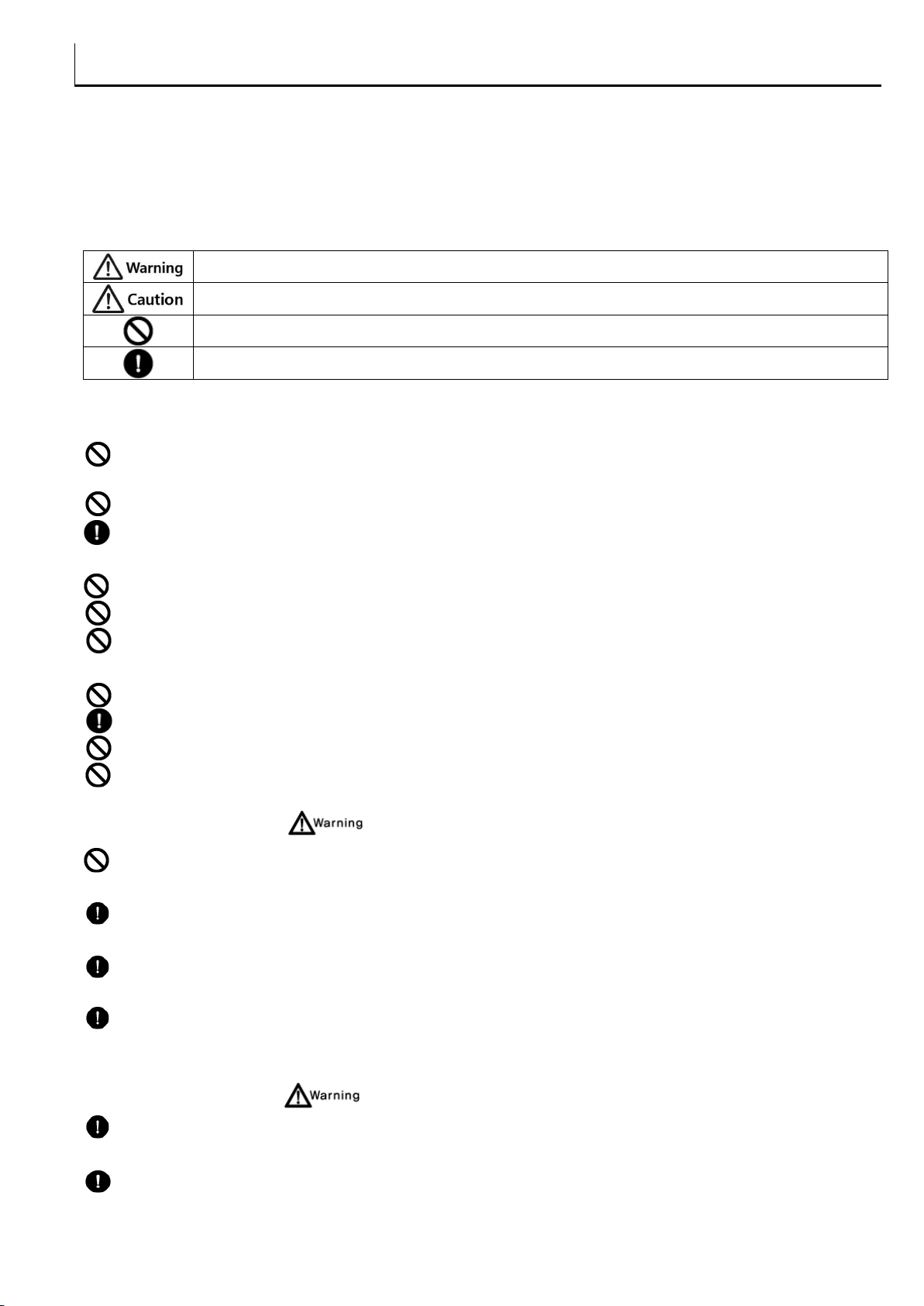
Chapter 1 Safety Precautions............................................................................................................................................................................. 3
Chapter 2 Overview ................................................................................................................................................................................................ 5
2.1 Introduction of Products............................................................................................................................................... 5
2.2 Package Contents............................................................................................................................................................. 5
2.3 Explanation of Model Name ....................................................................................................................................... 5
Chapter 3 General Specifications ..................................................................................................................................................................... 6
3.1 Power Specifications ....................................................................................................................................................... 6
3.2 Memory Specifications................................................................................................................................................... 6
3.3 HDMI Output...................................................................................................................................................................... 6
3.4 Environment Specifications.......................................................................................................................................... 6
3.5 Structure Specifications ................................................................................................................................................. 6
Chapter 4 Part Names and General Specifications.................................................................................................................................. 7
4.1 TOPRP1000D....................................................................................................................................................................... 7
4.2 Product Dimension .......................................................................................................................................................... 7
4.3 Part Names and General Specifications................................................................................................................. 7
Chapter 5 External Device Interface ............................................................................................................................................................... 8
5.1 Serial Communication Specifications ...................................................................................................................... 8
5.2 Ethernet Communication Specifications ................................................................................................................ 9
5.3 USB Specifications..........................................................................................................................................................10
5.4 HDMI Specifications ......................................................................................................................................................10
Chapter 6 Installation ..........................................................................................................................................................................................11
6.1 Location Select for Installation.................................................................................................................................11
6.2 DIN RAIL Mounting and VESA bracket bonding.............................................................................................11
Chapter 7 Wiring ...................................................................................................................................................................................................12
7.1 Power Cable Wiring.......................................................................................................................................................12
7.2 Ground Wiring .................................................................................................................................................................13
7.3 Installation of Cable Clamp .......................................................................................................................................14
Chapter 8 Maintenance ......................................................................................................................................................................................14
8.1 Case Cleaning...................................................................................................................................................................14
8.2 Periodic Check Points...................................................................................................................................................14
8.3 Problems with the Device...........................................................................................................................................15
8.4 Setting System Recovery Mode...............................................................................................................................15
Chapter 9 Products Label ..................................................................................................................................................................................16

Industrial BOX-HMI Hardware Manual
M2I Corporation
11-35, Simin-daero 327beon-gil, Dongan-gu, Anyang-si, Gyeonggi-do 14055, Korea, Tel: +82-70-465-3366, Fax: +82-31-465-3355, www.m2i.co.kr
3 / 16
Chapter 1 Safety Precautions
■Before using the product
To use the product safely and effectively, please read the contents of this manual thoroughly before use. Please
keep to the safety precaution, for it is to prevent accidents and potential danger from occurring. Safety
precaution is classified into ‘Warning’and ‘Caution’and their meanings are as follows. Also the indicated
illustrations on the product and in the manual have the following meanings.
Violating the instruction may result in serious personal injury or death.
Violating the instruction may result in slight personal injury or product damage.
Be cautious, for danger may be present.
Be cautious, for there is a possibility of an electric shock.
■General Precautions
Do not press the screen with a hard or sharp object (awl, screwdriver, pen) with too strong a force.
It may cause malfunction of touch due to damage of the front sheet.
Do not use or store in an environment with high vibration.
Do not allow foreign objects such as water, liquids, or metal powders to enter the product. This may cause
breakage or electric shock.
Do not allow foreign objects such as water, liquids, or metal powders to enter into the product.
Use the radio or mobile phone at least 30cm away from the main unit.
Two or fewer bright spots may appear on the LCD screen, and certain areas may appear brighter, but this is
not a defect in LCD characteristics.
Do not store or operate in direct sunlight. Direct sunlight can change the properties of the LCD.
Do not touch an adaptor or power code with wet hands. It can cause electric shock.
Do not use this product in explosive environments with flammable liquid, gas, or dust.
If the product needs long-term storage without using, avoid direct sunlight and keep dry condition.
■Design Precautions
For protecting whole control system from outer power input or malfunction of product, protection circuit
must be installed outside of product.
Physical protection devices as emergency switch, limit switch, or motion interlock circuit and others to
prevent a critical damage of whole system’s safety and human accident from the product’s malfunction.
When computers or other outer devices control (operation mode change) the product, set interlock in
sequence program to protect from any communication errors.
Input/output signals or communication cables must have at least 100mm(3.94inch) distance from power
cable or high-tension wire. Especially communication cables must be set apart from power cables.
■Wiring Precautions
Be sure the wiring is done correctly by checking the product’s rated voltage and the terminal layout.
Incorrect wiring could result in fire, damage or malfunctions.
Tighten the terminal screw with the specified torque. If the screws of terminal are loose, it could result in
short circuit, fire, malfunctions. FG Terminal must be used a dedicated ground. Not doing so could result in

Industrial BOX-HMI Hardware Manual
M2I Corporation
11-35, Simin-daero 327beon-gil, Dongan-gu, Anyang-si, Gyeonggi-do 14055, Korea, Tel: +82-70-465-3366, Fax: +82-31-465-3355, www.m2i.co.kr
4 / 16
malfunctions.
a. Grounding should be the Class 3 grounding. The cable for grounding should be more than 4㎟.
b. grounding point be closed to the products and make short the distance to the ground cable if possible.
■Installation Precautions
Do not install the location which exceeds allowed temperature. Product can be damaged or shorten the life.
Especially Install environment as below should be avoided.
Do not Install product to the place which the ambient temperature is out of limits, from -10℃to 50℃or on the surface
of control board which high pressure equipment is installed.
Do not install to the place where strong shock or vibration continuously have impacted on product.
If the product is left without using in long-term, it must be recharged and stored in room temperature.
The space between back of product and back of control board must be more than 100mm for maintenance
and ventilation.
Use the product indoors only.
Use the product under 2000M altitute.
Power cable’s length should be 3M(10 ft) or shorter.
■Disposal Precautions
When you dispose of product and battery, please treat it as industrial waste. It can create poisonous substances
or explosion.
■Cell Type Battery Specifications and Exchange
Mounted on mainboard Model MS920SE Battery is not replaced by the user. If the battery has run out of service,
please contact our Customer Support Center for replacement and inspection.
Item
Content
Battery Voltage
DC 3V
Battery Model
MS920SE (lithium / Rechargeable)
Battery lifetime
Permanent (In case of ambient temperature 25℃)
*Depending on the model specifications are subject to change.
■All field-wiring connections to this unit shall be from Limited Voltage / Limited Current, below 24Vdc
isolated secondary source with an output fuse, or Class 2.

Industrial BOX-HMI Hardware Manual
M2I Corporation
11-35, Simin-daero 327beon-gil, Dongan-gu, Anyang-si, Gyeonggi-do 14055, Korea, Tel: +82-70-465-3366, Fax: +82-31-465-3355, www.m2i.co.kr
5 / 16
Chapter 2 Overview
2.1 Introduction of Products
This BOX-HMI is an industrial control device in the field, with the basic purpose of communications and
controls with other devices by RS-232C, RS-422/485, or Ethernet. Also this product can check the management
status by connecting to outer display device.
2.2 Package Contents
The components of the product are as follows.
Before using the product, please check that all of the following components are included.
Item
Figure
Quantity
Product and User Manual
1
Power Connector
1
Accessories
(Sold separate)
USB Memory
USB Cable
SD Card
케이블 고정 클램프
VESA 고정 브라켓
User Options
2.3 Explanation of Model Name
Base Unit
Option
Power
TOPRP
1000: Default
D: DC

Industrial BOX-HMI Hardware Manual
M2I Corporation
11-35, Simin-daero 327beon-gil, Dongan-gu, Anyang-si, Gyeonggi-do 14055, Korea, Tel: +82-70-465-3366, Fax: +82-31-465-3355, www.m2i.co.kr
6 / 16
Chapter 3 General Specifications
3.1 Power Specifications
Input Voltage
DC 24V
Input Voltage Range
DC 20 ~ 28V
Consumption Power
10W or less
Voltage endurance
DC 24V, within 10ms
Insulation Resistance
500V DC, 10 ㏁
3.2 Memory Specifications
Screen Memory
128MB
Backup Memory
512KB: System buffer (10K Word), Including Alarm/Log/Recipe
Backup Period
Permanent
Real Time Clock
Built in (by Battery)
3.3 HDMI Output
HDMI Version
HDMI v1.4a
Resolution
1280 x 720, 1024x768, 640x480 (Set in TDS S/W)
3.4 Environment Specifications
Operation Temperature (℃)
-10 ~ +50
Storage Temperature (℃)
-20 ~ +60
Operation Humidity (%RH)
0 ~ 90 (No dew)
Atmosphere
No corrosive gas
Vibration Endurance
Amplitude: 10≤F<25㎐(2G) X,Y,Z each direction(for 30 minutes)
Noise Immunity
1000Vp-p(Pulse width 1㎲)
Static Electricity Discharge
Connective discharge from EN61000-4-2: ±4㎸
Shock Endurance
10G X,Y,Z each direction(for 3 times)
Surge Voltage
500V(Line-Line)
Ground Connection
Class 3(Under 100Ω)
Protection Classification
IP20
3.5 Structure Specifications
Weight (Kg)
0.23
Cooling System
Natural Air Circulation
Installation
Standard DIN Rail(35mm), VESA
Case Material
PC(Flameless)

Industrial BOX-HMI Hardware Manual
M2I Corporation
11-35, Simin-daero 327beon-gil, Dongan-gu, Anyang-si, Gyeonggi-do 14055, Korea, Tel: +82-70-465-3366, Fax: +82-31-465-3355, www.m2i.co.kr
7 / 16
Chapter 4 Part Names and General Specifications
4.1 TOPRP1000D
4.2 Product Dimension
4.3 Part Names and General Specifications

Industrial BOX-HMI Hardware Manual
M2I Corporation
11-35, Simin-daero 327beon-gil, Dongan-gu, Anyang-si, Gyeonggi-do 14055, Korea, Tel: +82-70-465-3366, Fax: +82-31-465-3355, www.m2i.co.kr
8 / 16
No
Name
Form
Description
1
SD Card Socket
SD Card Socket
SD Memory card
2
USB OTG
Mini-USB
Upload/Download port for project
(*Only for Inner program management)
3
Mode Switch
DIP Switch
System mode selection switch
4
Reset Switch
Tact Switch
System reset switch
5
HDMI
Standard HDMI
HDMI Out port, Connecting to outer display device.
(TV/Monitor) *Max. Resolution 1280 x 720
6
USB HOST #1
USB A type
USB Connecting Port, 5V/0.5A Output
7
VESA Bracket
-
VESA hole for installation
8
COM1
DSUB9 (Female)
RS-232C/422/485 (Selection by S/W)
9
COM2
DSUB9 (Female)
RS-232C/422/485 (Selection by S/W)
10
Power Input
TB 5mm 3P
Power Input
11
Status LED
3 LEDs
Status display of Power, Operation, and SD Card
12
USB HOST #2
USB A type
USB Connecting Port, 5V/0.5A Output
13
ETHERNET Port
RJ45 2ch
10BASE-T/100BASE-TX, Auto-MDIX
14
DIN RAIL
-
DIN RAIL Holding Bracket (35mm)
Chapter 5 External Device Interface
In order for the main unit to communicate with an external device, it is necessary to connect the two devices
by referring to the following.
5.1 Serial Communication Specifications
5.1.1 RS-232C
Items
Contents
Protocol
Full Duplex
Synch
Asynchronous
Communication Distance
About 15m
Type of Connection
1:1
Control Code
ASCII Code or HEXA Code
Transmission Speed
2400,4800,9600,19200,38400,57600,76800, 115200 bps
Data Type
Data Bit
7, 8 bit
Parity Bit
NONE, ODD, EVEN Parity
Stop Bit
1, 2 bit
Modular Jack
DSUB 9pin
5.1.2 RS-422/485
Items
Contents
Protocol
Full Duplex/Half Duplex
Synch
Asynchronous
Communication Distance
About 500m
Type of Connection
1:N(N ≤31)
Control Code
ASCII Code or HEXA Code

Industrial BOX-HMI Hardware Manual
M2I Corporation
11-35, Simin-daero 327beon-gil, Dongan-gu, Anyang-si, Gyeonggi-do 14055, Korea, Tel: +82-70-465-3366, Fax: +82-31-465-3355, www.m2i.co.kr
9 / 16
Transmission Speed
2400,4800,9600,19200,38400,57600,76800, 115200 bps
Data Type
Data Bit
7, 8 bit
Parity Bit
NONE, ODD, EVEN Parity
Stop Bit
1, 2 bit
Modular Jack
DSUB 9pin
5.1.3 COM1 Connector pin number and Signal name
Type
Pin No.
Signal
Direction
Meaning
9Pin Female
1
RDA(RD+)
Input
RS-422/485 Receive Data (+)
2
RD(RxD)
Input
RS-232C Receive Data
3
SD(TxD)
Output
RS-232C Send Data
4
RDB(RD-)
Input
RS-422/485 Receive Data (-)
5
SG
-
Signal Ground
6
SDA(SD+)
Output
RS-422/485 Send Data (+)
7
*1)Power
-
+5V , 0.2A
8
*2)GND
-
Power Ground
9
SDB(SD-)
Output
RS-422/485 Send Data (-)
*1, *2) When need VCC for external equipment, use 7.VCC and 8.VCC GND that output is 0.2A.
5.1.4 COM2 Connector pin number and Signal name
Type
Pin No.
Signal
Direction
Meaning
9Pin Female
1
RDA(RD+)
Input
RS-422/485 Receive Data (+)
2
RD(RxD)
Input
RS-232C Receive Data
3
SD(TxD)
Output
RS-232C Send Data
4
RDB(RD-)
Input
RS-422/485 Receive Data (-)
5
SG
-
Signal Ground
6
SDA(SD+)
Output
RS-422/485 Send Data (+)
7
RTS
Output
RS-232C Send Request Signal
8
CTS
Input
RS-232C Send Available Signal
9
SDB(SD-)
Output
RS-422/485 Send Data (-)
* Be sure to connect the RD and SD to the RS-232C communication line by crossing each other with a Twisted Pair Cable.
Please connect SG directly.
* SG must be connected directly.
* RS-422/485 communication line must use RDA and RDB as Twisted Pair Cable, SDA and SDB as Twisted Pair
Cable.
* Do not use shield wire of communication line as signal ground. It may cause communication failure.
5.2 Ethernet Communication Specifications
5.2.1 Ethernet
Items
Contents
Ethernet Method
IEEE802.3i/IEEE802.3u, 10BaseT / 100BaseT
Speed
10M / 100Mbps
Communication Method
Base Band
Switching Method
AUTO MDIX

Industrial BOX-HMI Hardware Manual
M2I Corporation
11-35, Simin-daero 327beon-gil, Dongan-gu, Anyang-si, Gyeonggi-do 14055, Korea, Tel: +82-70-465-3366, Fax: +82-31-465-3355, www.m2i.co.kr
10 / 16
Maximum Segment Length
100M (Hub between products)
Communication Cable
UTP (Unshielded Twisted Pair)
Modular Jack
RJ45
5.2.2 RJ–45 Pin Map
Type
Pin No.
Color
Signal
1
Orange/White
TD+
2
Orange
TD-
3
Green/White
RD+
4
Blue
Not Available in 10BaseT
5
Blue/White
Not Available in 10BaseT
6
Green
RD-
7
Brown/White
Not Available in 10BaseT
8
Brown
Not Available in 10BaseT
* When HUB is using, Straight cable should be used.
Ex) Straight Cable Wiring: Connect 1:1 according to the wiring diagram above.
* In case of do not using HUB, do not use HUB, when it is connected directly, Cross Cable should be used.
Ex) Cross Cable Wiring: In the above wiring diagram, TD+ and RD+ are changed, and TD- and RD- are exchanged.
5.3 USB Specifications
5.3.1 USB Host
Type
Item
Specification
USB Interface
EHCI/OHCI Specification Version 1.0, USB2.0/1.1 compatible
Communication Method
Control/Bulk
Transfer Speed
480Mb/s
Support Device
USB Storage (FAT16/FAT32 File Format Available)
Connector Type
Type A(1ch)
5.3.2 USB OTG
Type
Item
Specification
USB Interface
USB 2.0
Communication Method
Interrupt/Bulk/Isochronous
Transfer Speed
480Mb/s
Supporting OS
Windows 98SE/2000/XP/VISTA/7/10(32/64bit)
Cable Length
1.5M(recommended to use M2I's Option Cable)
Connect Type
MINI USB B, Female
Connect Method
Connect through USB OTG
5.4 HDMI Specifications
Type
Item
Specification
HDMI Version
HDMI v1.4a
Supportive Resolutions
1280 x 720, 1024x768, 640x480 (Set in TDS S/W)
Connector Type
HDMI Type A

Industrial BOX-HMI Hardware Manual
M2I Corporation
11-35, Simin-daero 327beon-gil, Dongan-gu, Anyang-si, Gyeonggi-do 14055, Korea, Tel: +82-70-465-3366, Fax: +82-31-465-3355, www.m2i.co.kr
11 / 16
Chapter 6 Installation
6.1 Location Select for Installation
(1) This product should have at least 100mm space from other devices and be free from any mechanical
hazards for safe use.
(2) The installation should be done in -10~50℃and 10~80% environment.
(3) If this product is installed in sealed space, cooling fan must be installed.
(4) Do not make power cable and communication cable be neighboring. It can cause malfunction from noise.
(5) An install location should be separated from power line and I/O cables which has a lot of noise. Also make
the wiring length short as possible.
6.2 DIN RAIL Mounting and VESA bracket bonding
This product has DIN Rail (width 35mm) Hook for mounting.
6.2.1 DIN RAIL

Industrial BOX-HMI Hardware Manual
M2I Corporation
11-35, Simin-daero 327beon-gil, Dongan-gu, Anyang-si, Gyeonggi-do 14055, Korea, Tel: +82-70-465-3366, Fax: +82-31-465-3355, www.m2i.co.kr
12 / 16
6.2.2 VESA bracket
(1) Standard of VESA bracket
(2) When a VESA Bracket is attached, four fixing grooves should be put correctly.
Chapter 7 Wiring
7.1 Power Cable Wiring
(1) The Power cable should have the following specification.
Power Cable Specification
0.75~2.5mm2(18~13AWG)
F.G Cable Specification
Over 2mm2(14AWG)
Conductor Type
Simple or Standard Wire
Bolt tightening force
≥0.4 N.m
Conductor Length
Temperature rating of the
field installed conductors
65℃or under

Industrial BOX-HMI Hardware Manual
M2I Corporation
11-35, Simin-daero 327beon-gil, Dongan-gu, Anyang-si, Gyeonggi-do 14055, Korea, Tel: +82-70-465-3366, Fax: +82-31-465-3355, www.m2i.co.kr
13 / 16
(2) Pin Terminal Wiring
Caution: It is important to use Pin Terminal of power cable and contact terminals for maintaining a product’s
performance. Without using Pin Terminal which is not following this specification can cause electric shocks from
abnormal cable connection. User should be well-informed about this Pin Terminal guide.
(mm)
B
L
F
E
D
d
1.8~2.0
22~18
12~14
5
3.3~3.8
2~2.5
(3) Wiring of power is as follows.
7.2 Ground Wiring
(1) The product has enough anti-noise measure, so except that there are many noises. Specially, the ground is
not needed. When doing ground, please refer to the followings.
(2) The ground should be the exclusive ground. The ground should be type Class 3 ground. (ground resistor is
less than 100Ω.)
(3) When you cannot do the exclusive ground, do common ground like figure B.
A) Exclusive ground
B) Common ground
C) Common ground

Industrial BOX-HMI Hardware Manual
M2I Corporation
11-35, Simin-daero 327beon-gil, Dongan-gu, Anyang-si, Gyeonggi-do 14055, Korea, Tel: +82-70-465-3366, Fax: +82-31-465-3355, www.m2i.co.kr
14 / 16
(4) Use the cable more than 4mm2. Put the point of the ground near product and shorten Ground line.
7.3 Installation of Cable Clamp
Caution: This cable clamps are installed for preventing disconnection and electronic sparks by loosen or
breaking out of port and cable. Users should be well-informed about following guide.
(1) Put HDMI or USB cables through cable clamp as following image.
(2) Tighten the cable and clamp as following image, and use screw and bolt to fix the clamp to a product.
Chapter 8 Maintenance
8.1 Case Cleaning
Use soft cloth wet by detergent to wipe dirty surface of case out.
8.2 Periodic Check Points
Check the followings periodically for best condition of the device.
(1) Environment
1) Is the operating temperature within the allowable range (-10°C~50°C)?
2) Is the operating humidity within the allowable range (10%~80%RH)?
3) Is the Surrounding pollution no corrosive gas?
(2) Power
1) Is the input power in right range?
(3) Related Items
1) Check the touch pad there is no damage, scratch or pollution by eye.

Industrial BOX-HMI Hardware Manual
M2I Corporation
11-35, Simin-daero 327beon-gil, Dongan-gu, Anyang-si, Gyeonggi-do 14055, Korea, Tel: +82-70-465-3366, Fax: +82-31-465-3355, www.m2i.co.kr
15 / 16
8.3 Problems with the Device
(1) If there is a problem during operation, stop using it and contact the A/S department of M2I Corporation,
which is indicated on the product label.
(2) Only the authorized worker from M2I Corporation can check and repair problems related to malfunction of
the machine.
(3) If the problem cannot be solved at the installation site, the equipment can be collected and moved to M2I
Corporation.
(4) The manufacturer, M2I Corporation, is not responsible for damage or malfunction of the equipment caused
by the use conditions of the user beyond the installation and use standards described in the manual.
(5) When electromagnetic noise is over-radiated, Install the ferrite core to the body power and field power lines.
Depending on the installation environment, noise from power lines and communication lines may be high.
(6) In noisy places, recommended use of industrial display devices.
(7) If the HDMI and USB devices do not operate normally due to noise, install ferrite cores on both ends of the
cable to improve noise tolerance.
8.4 Setting System Recovery Mode
(1) If the system fails to boot normally due to a problem during operation, the built-in recovery function can be
used to maintain the factory default state. Please note that the built-in project will be deleted when using the
recovery mode.
(2) By the mode switch on side, you can adjust the setting switch. Keep the "Normal" state when booting
normally. If the system is recovering, turn off the power and set it to "Factory Reset".
(3) When the recovery is completed, the buzzer sounds, then turn off the power and reset to "Normal" state.

Industrial BOX-HMI Hardware Manual
M2I Corporation
11-35, Simin-daero 327beon-gil, Dongan-gu, Anyang-si, Gyeonggi-do 14055, Korea, Tel: +82-70-465-3366, Fax: +82-31-465-3355, www.m2i.co.kr
16 / 16
Chapter 9 Products Label
Manufacture (AS): M2I Corporation
11-35, Simin-daero 327beon-gil, Dongan-gu, Anyang-si, Gyeonggi-do 14055, Korea
Tel: 82-31-465-3366
Product Category: Industrial BOX-HMI
Model Name: TOPRP1000D
Operating Temp: -10 ℃≤Ta ≤+50 ℃
Power Specifications: 24Vdc, 10W or under
Inside Cell: MS920SE (Rechargeable lithium Battery/irreplaceable)
Copyright: M2I Corporation 2022.08 www.m2i.co.kr
- Please read related contents in this manual when you use M2I product, and operate the product staying
safe with appropriate handling.
- This manual should be stored in secured and appointed place so that it can be read in any needs.
User Guide
This product has Relevant Assessments for business environment. If this product is used in home
environment, there can be an interference.
This manual suits for next models
1
Table of contents
Other M2I Industrial PC manuals
Popular Industrial PC manuals by other brands

Moxa Technologies
Moxa Technologies IA260 series Quick installation guide

SmartCow
SmartCow Uranus user manual

Cybernet
Cybernet CyberMed NB20 user manual

Neousys Technology
Neousys Technology Nuvo-10208GC Series user manual

Aerotech
Aerotech Automation1 iPC Series Hardware manual

Vecow
Vecow VCOM-1600 user manual