M2I TOP-PCVIEW Series User manual

TOP-PCVIEW Hardware Manual
M2I Corporation 1/ 33
11-35, Simin-daero 327beon-gil, Dongan-gu, Anyang-si, Gyeonggi-do 14055, Korea, Tel: +82-70-465-3366, Fax: +82-31-465-3355, www.m2i.co.kr
M2I Corporation
Industrial PC-HMI
TOP-PCVIEW
Hardware Manual
Thank you for using TOP-PCVIEW series of M2I corporation.
Please read this manual carefully to know installing, wiring, operating, servicing and inspecting this equipment.

TOP-PCVIEW Hardware Manual
M2I Corporation 2/ 33
11-35, Simin-daero 327beon-gil, Dongan-gu, Anyang-si, Gyeonggi-do 14055, Korea, Tel: +82-70-465-3366, Fax: +82-31-465-3355, www.m2i.co.kr
Contents
Chapter 1. Safety Precautions................................................................................................................................................................ 4
Before using the product............................................................................................................................................ 4
General Precautions....................................................................................................................................................... 4
Design Precautions ........................................................................................................................................................ 4
Normal environmental conditions .......................................................................................................................... 4
Wiring Precautions......................................................................................................................................................... 4
Installation Precaution.................................................................................................................................................. 5
Disposal Precaution ....................................................................................................................................................... 5
Cell Type Battery Specifications and Exchange................................................................................................ 5
Chapter 2. Overview................................................................................................................................................................................... 6
2.1 Product Introduction....................................................................................................................................................... 6
2.2 Package Contents............................................................................................................................................................. 6
2.3 Explanation of Model Name ....................................................................................................................................... 7
Chapter 3. Product Specifications........................................................................................................................................................ 7
3.1 Electrical Specifications.................................................................................................................................................. 7
3.2 System Specifications ..................................................................................................................................................... 7
3.3 LCD Specifications............................................................................................................................................................ 8
3.4 Touch Specifications ....................................................................................................................................................... 8
3.5 Ethernet Specifications................................................................................................................................................... 8
3.6 Audio Specifications........................................................................................................................................................ 8
3.7 External Display Output Specifications................................................................................................................... 8
3.8 USB Specifications............................................................................................................................................................ 8
3.9 Etc. ........................................................................................................................................................................................... 8
3.10 Options Specifications ................................................................................................................................................. 8
3.11 Environment Specifications ....................................................................................................................................... 9
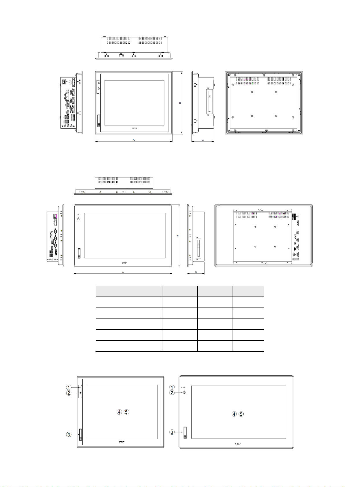
3.12 Structure Specifications............................................................................................................................................... 9
Chapter 4. Parts Identification and Functions................................................................................................................................ 9
4.1 TOP-PCVIEW10 .................................................................................................................................................................. 9
4.2 TOP-PCVIEW12 / 15 / 17............................................................................................................................................10
4.3 TOP-PCVIEW19 ................................................................................................................................................................10
4.4 Front Parts Names and Specifications..................................................................................................................10
4.5 Side Parts Names and Specifications....................................................................................................................11
Chapter 5. Installation .............................................................................................................................................................................12
5.1 Installation Requirements ...........................................................................................................................................12
5.3 Front USB (*Locker type, Option) ...........................................................................................................................14
Chapter 6. Peripheral device Interface ............................................................................................................................................15
6.1 Serial Communication Mode setting and specifications .............................................................................15
6.2 Ethernet setting and specifications........................................................................................................................17
6.3 USB Specification............................................................................................................................................................18
Chapter 7. Wiring ......................................................................................................................................................................................19
7.1 Power wiring .....................................................................................................................................................................19
7.2 Ground wiring ..................................................................................................................................................................19
Chapter 8. System Utilities.....................................................................................................................................................................20

TOP-PCVIEW Hardware Manual
M2I Corporation 3/ 33
11-35, Simin-daero 327beon-gil, Dongan-gu, Anyang-si, Gyeonggi-do 14055, Korea, Tel: +82-70-465-3366, Fax: +82-31-465-3355, www.m2i.co.kr
8.1. System Recovery Solution.........................................................................................................................................20
8.2 Touch panel compensation .......................................................................................................................................22
8.3. EWF (Enhanced Write Filter) Set ............................................................................................................................23
8.4. Backlight brightness settings ...................................................................................................................................24
8.5. RAID Setting (*Premium Model) ............................................................................................................................25
Chapter 9. Maintenance .........................................................................................................................................................................31
9.1 Cleaning the Display.....................................................................................................................................................31
9.3 Problems with the Device...........................................................................................................................................31
Chapter 10. Products and Warning Label Location ..................................................................................................................32
10.1 TOP-PCVIEW12x0X / 15x0X ....................................................................................................................................32
10.2 TOP-PCVIEW19x0H......................................................................................................................................................32
Chapter 11. Products Label...................................................................................................................................................................33
11.1 AC Power Models ........................................................................................................................................................33
11.2 DC Power Models........................................................................................................................................................33

TOP-PCVIEW Hardware Manual
M2I Corporation 4/ 33
11-35, Simin-daero 327beon-gil, Dongan-gu, Anyang-si, Gyeonggi-do 14055, Korea, Tel: +82-70-465-3366, Fax: +82-31-465-3355, www.m2i.co.kr
Chapter 1. Safety Precautions
Before using the product
To use the product safely and effectively, please read the contents of this manual thoroughly before use.
Please keep to the safety precaution, for it is to prevent accidents and potential danger from occurring.
Safety precaution is classified into ‘Warning’ and ‘Caution’ and their meanings are as follows. Also the
indicated illustrations on the product and in the manual have the following meanings.
Violating the instruction may result in serious personal injury or death.
Violating the instruction may result in slight personal injury or product damage.
Be cautious, for danger may be present.
Be cautious, for there is a possibility of an electric shock.
General Precautions
Do not press the screen with a hard or sharp object (awl, screwdriver, pen) with too strong a force.
It may cause malfunction of touch due to damage of the front sheet.
Do not use or store in an environment with high vibration.
Do not allow foreign objects such as water, liquids, or metal powders to enter the product. This may cause
breakage or electric shock.
Do not allow foreign objects such as water, liquids, or metal powders to enter into the front(screen)
protective sheet. The screen may be invisible or may cause a malfunction of the touch.
Use the radio or mobile phone at least 30cm away from the main unit.
Two or fewer bright spots may appear on the LCD screen, and certain areas may appear brighter, but this
is not a defect in LCD characteristics.
Do not store or operate in direct sunlight. Direct sunlight can change the properties of the LCD.
Design Precautions
Do not install the location which exceeds allowed temperature. Product can be damaged or shorten the life.
Especially Install environment as below should be avoided.
As the malfunction & incorrect result of Products could damage the stability of the entire systems and
human body, you must install damage preventing interlock circuit such as emergency stop, Protective
circuits, positioning upper and lower limit switch and interlock for forward/reverse operation.
When computer or other controllers communicate and exchange data with products or change operation mode of
products, set up protective sequence program in PC or Controller for protecting system from communication error.
The output signal or communication lines should be separated from the power line or high tension wire.
They should be installed 100mm (3.94 inch) or more from each other.
Normal environmental conditions
Indoor use.
Altitude up to 2000m.
Wiring Precautions
Be sure the wiring is done correctly by checking the product’s rated voltage and the terminal

TOP-PCVIEW Hardware Manual
M2I Corporation 5/ 33
11-35, Simin-daero 327beon-gil, Dongan-gu, Anyang-si, Gyeonggi-do 14055, Korea, Tel: +82-70-465-3366, Fax: +82-31-465-3355, www.m2i.co.kr
layout. Incorrect wiring could result in fire, damage or malfunctions.
Tighten the terminal screw with the specified torque. If the screws of terminal are loose, it could result in
short circuit, fire, malfunctions. FG Terminal must be used a dedicated ground. Not doing so could result in
malfunctions.
a. Grounding should be the Class 3 grounding. The cable for grounding should be more than 4㎟.
b. grounding point be closed to the products and make short the distance to the ground cable if possible. Please see
below.
Installation Precaution
Do not install the location which exceeds allowed temperature. Product can be damaged or shorten the life.
Especially Install environment as below should be avoided.
Do not Install product to the place which the ambient temperature is out of limits, from 0℃to 60℃or on
the surface of control board which high pressure equipment is installed.
Do not install to the place where strong shock or vibration continuously have impacted on product.
The space between back of product and back of control board must be more than 100mm for maintenance
and ventilation.
Do not storage and operate in the place in direct sunlight. By the strong ultraviolet rays can degrade the quality
of LCD Displays.
Disposal Precaution
When you dispose of product, please treat it as industrial waste. It can create poisonous substances or
explosion.
Cell Type Battery Specifications and Exchange
If a "CMOS CHECKSUM ERROR" occurs during booting, the BIOS setup can not be saved due to the
exhaustion of the CMOS battery, so users should replace the button battery that is fixed in the product.
Item
Content
Battery Voltage
DC 3V
Battery Model
CR2032(lithium Battery)
Battery lifetime
About 3 years (In case of ambient temperature 25℃)
Image
* Depending on the model specifications are subject to change.
All field-wiring connections to this unit shall be from Limited Voltage / Limited below 24Vdc isolated
secondary source with an output fuse, or Class 2.

TOP-PCVIEW Hardware Manual
M2I Corporation 6/ 33
11-35, Simin-daero 327beon-gil, Dongan-gu, Anyang-si, Gyeonggi-do 14055, Korea, Tel: +82-70-465-3366, Fax: +82-31-465-3355, www.m2i.co.kr
Chapter 2. Overview
2.1 Product Introduction
The industrial PC-HMI touch panel with industrial PC is required in industry, Windows applications, and RS-
232/422/485, Ethernet-based Control of the other devices that are connected to this unit (PLC) is a device used
to communicate with the primary objective.
2.2 Package Contents
please make sure that all of components are in the package.
Pictures shown may vary as a guide for understanding the real.
Item
Figure
Quantity
Main Body
1
User Manual
1
Power Connector
1
Terminal block
5P connector
1
Mounting Clamp
6
Accessories
(Sold separate)
USB Memory
User Options

TOP-PCVIEW Hardware Manual
M2I Corporation 7/ 33
11-35, Simin-daero 327beon-gil, Dongan-gu, Anyang-si, Gyeonggi-do 14055, Korea, Tel: +82-70-465-3366, Fax: +82-31-465-3355, www.m2i.co.kr
2.3 Explanation of Model Name
▲Basic Model
TOP-PCVIEW
□□
□□
□
□
Series
Display Size
Option
Resolution
Power Type
10 : 10.4"
00 : Standard
X : XGA (1024 x 768)
A: AC
12 : 12.1"
10 : Premium
S : SXGA (1280 x 1024)
D: DC
15 : 15.0”
H : HD (1366 x 768)
17 : 17.0"
19 : 18.5"
▲Option
□□ -
□□
□□
□□
□BAY
Built-in program
RAM Capacity
O/S installation location
DISK Capacity
HDD RACK
WF : WES7, TOPVIEW
R4 : 4GB
H : mSATA
64 : 64GB
1 : 1 Slot
WN : WES7
R8 : 8GB
HE : 2.5" SSD
128 : 128GB
2 : 2 Slot
NF : TOPVIEW
256 : 256GB
NN : N/A
* RAM and disk storage are optional.
Chapter 3. Product Specifications
3.1 Electrical Specifications
Input Voltage
AC Power
AC100~240V, 50/60Hz
DC Power
DC 24V
Voltage Endurance
AC Power
AC85/170V, Less than 10ms
DC Power
DC 24V, Less than 10ms
Power Consumption
50W or less
Insulation resistance
500V DC, 10 ㏁
3.2 System Specifications
CPU
Standard
Intel® Celeron® Processor J1900
Premium
Intel® Core-i3™Processor 4010U
Base/Burst
Frequency
Standard
Premium
1.7GHz
TDP
Standard
10W
Premium
15W
Main Memory
DDR3L SO-DIMM 8GB. (Max. Capacity 8GB)
Main Disk
2.5" SSD 256GB (*Default)

TOP-PCVIEW Hardware Manual
M2I Corporation 8/ 33
11-35, Simin-daero 327beon-gil, Dongan-gu, Anyang-si, Gyeonggi-do 14055, Korea, Tel: +82-70-465-3366, Fax: +82-31-465-3355, www.m2i.co.kr
3.3 LCD Specifications
BLU
LED
Resolution and
Luminance
TOP-PCVIEW10
1024 X 768, 470 cd/m2
TOP-PCVIEW12
1024 x 768, 700 cd/m2
TOP-PCVIEW15
1024 x 768, 500 cd/m2
TOP-PCVIEW17
1280 x 1024, 250 cd/m2
TOP-PCVIEW19
1366 x 768, 250 cd/m2
Number of Colors
16.7M
3.4 Touch Specifications
Touch Type
Analog resistive touch
3.5 Ethernet Specifications
Speed
10/100/1000Mbps
Connector
RJ-45 x 2
3.6 Audio Specifications
Audio Codec
Realtek ALC888S
I/O Connector
SPK, Line-in, MIC
3.7 External Display Output Specifications
Controller
Standard
Intel Gen7 Graphic Engine
Premium
Intel HD Graphics 4400
VGA
Standard
Max. 2560 x 1600 at 60Hz
Premium
Max. 1920 x 1200 at 60 Hz
HDMI
Standard
HDMI 1.4a for HD video playback, 1080P at 60Hz
Premium
HDMI 1.4 for HD video playback, 3200 x 2000 1080P at 60Hz
Mulit-Display
Standard
VGA + HDMI, VGA + LVDS, HDMI + LVDS
Premium
VGA + HDMI, VGA + LVDS, HDMI + LVDS, VGA + HDMI + LVDS
3.8 USB Specifications
Front
Standard
USB 2.0 x 1
Premium
USB 2.0 x 1
Side
Standard
USB 2.0 x 3, USB 3.0 x 1
Premium
USB 2.0 x 2, USB 3.0 x 2
3.9 Etc.
HDD RACK
Support 1-Bay 2.5" HDD or SSD RACK
* 10 "product does not support HDD RACK.
* If you need 2-bay HDD RACK, please contact M2I Corporation.
3.10 Options Specifications
O/S
Windows Embedded Standard 7 32/64bit KOR/ENG Ver.
Windows Professional for Embedded System Ver.
USB KEY
TOPVIEW usb key certification

TOP-PCVIEW Hardware Manual
M2I Corporation 9/ 33
11-35, Simin-daero 327beon-gil, Dongan-gu, Anyang-si, Gyeonggi-do 14055, Korea, Tel: +82-70-465-3366, Fax: +82-31-465-3355, www.m2i.co.kr
3.11 Environment Specifications
Operation Temperature(℃)
No humidity
0 ~ +60°C
humidity 95%
0 to +40°C (Non-Condensing)
Storage Temperature(℃)
-20°C ~ +60°C
Atmosphere
No corrosive gas
Vibration Endurance
Amplitude: 10≤F<25 ㎐(2G) X,Y,Z each direction (for 30 minutes)
Noise Immunity
1000Vp-p (Pulse width 1 ㎲)
Electrostatic Discharge
Electrostatic Discharge from EN61000-4-2: ±4㎸
Shock Endurance
10G X,Y,Z each direction(for 3 times)
withstand voltage
500V (Line-Line)
Ground connection
Class 3(Under 100Ω)
Protection Classification
Front Side: IP65, Rear Side: IP2X
3.12 Structure Specifications
Dimension(㎜)
TOP-PCVIEW10
276 x 219.5 x 87.9
TOP-PCVIEW12
320 x 261 x 93.5
TOP-PCVIEW15
370 x 301 x 87
TOP-PCVIEW17
414 x 348 x 86.6
TOP-PCVIEW19
497 x 316 x 86.6
Cooling System
Natural air circulation
Case Material
AL(Aluminium)
Chapter 4. Parts Identification and Functions
4.1 TOP-PCVIEW10

TOP-PCVIEW Hardware Manual
M2I Corporation 10 / 33
11-35, Simin-daero 327beon-gil, Dongan-gu, Anyang-si, Gyeonggi-do 14055, Korea, Tel: +82-70-465-3366, Fax: +82-31-465-3355, www.m2i.co.kr
4.2 TOP-PCVIEW12 / 15 / 17
4.3 TOP-PCVIEW19
Model
A(mm)
B(mm)
C(mm)
TOP-PCVIEW10
276
219.5
87.9
TOP-PCVIEW12
320
261
93.5
TOP-PCVIEW15
370
301
87
TOP-PCVIEW17
414
348
86.6
TOP-PCVIEW19
497
316
86.6
4.4 Front Parts Names and Specifications

TOP-PCVIEW Hardware Manual
M2I Corporation 11 / 33
11-35, Simin-daero 327beon-gil, Dongan-gu, Anyang-si, Gyeonggi-do 14055, Korea, Tel: +82-70-465-3366, Fax: +82-31-465-3355, www.m2i.co.kr
No.
Item
Description
①
Power LED
Display the System Power State
②
Front power
switch
System power on / off touch switch
(* On/off contact for more than 3 seconds)
③
USB Port
Front USB HOST Port
④
TFT LCD
TFT 16M Color LCD
⑤
Touch Panel
Analog resistive touch type
4.5 Side Parts Names and Specifications
No.
Item
Type
Description
1
Power Switch
Rocker Switch-2P
System power ON / OFF switch
2
Power Connector
Terminal Block-3P
Power input, Pitch 7.62mm
3
Disk LED
LED
Display Disk operation status
4
Power LED
LED
Display Disk operation status
5
LAN Port #1, #2
RJ-45 2Ch.
Ethernet communication ports,
configurable independently of IP
6
VGA
DSUB-15P
VGA external monitor connection
7
HDMI
HDMI
HDMI external monitor connection
8
USB #1
USB 2Ch.
USB Ports
9
USB #2
USB 2Ch.
USB Ports
10
SPK
3.5Pi Audio JACK
Audio output
11
LINE-IN
3.5Pi Audio JACK
External Audio input
12
MIC
3.5Pi Audio JACK
External Mic input
13
COM1
DSUB-9 (Male)
RS-232C Port
14
COM2
DSUB-9 (Male)
RS-232C Port
15
COM3
DSUB-9 (Male)
RS-232C/422/485 Port
16
COM4
Terminal Block-5P
RS-232C/422/485 Port, Pitch 3.50mm
17
HDD Rack
2.5" bay Slot
2.5" External Hard drive Rack

TOP-PCVIEW Hardware Manual
M2I Corporation 12 / 33
11-35, Simin-daero 327beon-gil, Dongan-gu, Anyang-si, Gyeonggi-do 14055, Korea, Tel: +82-70-465-3366, Fax: +82-31-465-3355, www.m2i.co.kr
Chapter 5. Installation
5.1 Installation Requirements
(1) To safe use of the product, keep the 100mm space between the wall and the product. And install the
cooling fan in an enclosed space to ensure performance and ventilation.
(2) TOP PC should be installed within 0 ~ 60°C(relative-humidity 0%) or 0~40°C(relative-humidity less than 95%,
(Non-Condensing)), otherwise the screen may be changed or cause malfunction and damage.
(3) Be sure that heat from surrounding equipment does not cause TOP PC to exceed its standard operating
temperature.
(4) When you don’t see within 30°, you may not see clearly.
(5) When installing the TOP PC in a slanted position, TOP PC screen should not incline more than 30°
5.2 Installation Procedure
For mounting product to the control panel, it should be recommended following below items.
5.2.1 Panel Cut-out
Make a panel cut which product is mounted and insert the TOP PC to the panel form the front side.
(1) The Size of Panel Cut (Mounting Place)
Making the Panel Cut (Mounting Size) per each TOP PC Series as below Table, Before Installation.
Model
A(mm)
B(mm)
R(mm)
TOP-PCVIEW10
260.0
202.0
Max. 5.0
TOP-PCVIEW12
306.0
247.0
Max. 5.0
TOP-PCVIEW15
355.0
286.0
Max. 5.0
TOP-PCVIEW17
400.0
334.0
Max. 2.0
TOP-PCVIEW19
479.0
298.0
Max. 2.0
IP65
IP2X
0 ~ 60°C
0 ~ 60°C

TOP-PCVIEW Hardware Manual
M2I Corporation 13 / 33
11-35, Simin-daero 327beon-gil, Dongan-gu, Anyang-si, Gyeonggi-do 14055, Korea, Tel: +82-70-465-3366, Fax: +82-31-465-3355, www.m2i.co.kr
(2) Fixation
Installation methods should be following by using the supplied installation Clamps.
a. Insert the clamp into the slot of Product.
b. Secure the Product in the mounting cut-out from behind with the clamp.
c. If the screw is over tightened, it may cause the front deformation, thus resulting the touch sensor can’t
work properly. Tighten the screw to 0.5 Nm.

TOP-PCVIEW Hardware Manual
M2I Corporation 14 / 33
11-35, Simin-daero 327beon-gil, Dongan-gu, Anyang-si, Gyeonggi-do 14055, Korea, Tel: +82-70-465-3366, Fax: +82-31-465-3355, www.m2i.co.kr
5.3 Front USB (*Locker type, Option)
5.3.1 Opening the Front USB cover
Insert the Micro USB Connector in the hole on the top of the Front USB Cover.
The USB Cover can be opened once you push the Front USB Cover.
(1) Open the cover: The cover opens when you insert the USB connector into the front USB Home.
(2) Gender Remove: Hold down the button below and pull back the USB gender.
(3) Close the cover: Close and slide the cover of the connector.
* Locker type USB cover is required for front USB gender use. Please contact M2I Corporation.
Push

TOP-PCVIEW Hardware Manual
M2I Corporation 15 / 33
11-35, Simin-daero 327beon-gil, Dongan-gu, Anyang-si, Gyeonggi-do 14055, Korea, Tel: +82-70-465-3366, Fax: +82-31-465-3355, www.m2i.co.kr
Chapter 6. Peripheral device Interface
For Serial communication, please refer below tables of each TOP-PCVIEW Model.
6.1 Serial Communication Mode setting and specifications
6.1.1. Set serial communication mode
(1) Boot <DEL> or <ESC> Press the key to set the communication mode can be changed in CMOS.
(2) Advanced -> IT8768(E) Super IO Configuration -> Select the appropriate serial port -> [Serial Port] Mode
Select one of the [RS-232 Mode], [RS-422 Mode], [RS-485 Mode]
a. Standard Type
b. Premium Type
(3) Serial communication modes to choose from depending on the serial communication port.
(4) The communication mode can be set as the table below.
COM1
COM2
COM3
COM4
Manufacturer status
RS-232C
RS-232C
RS-485
RS-485
Available settings
Not available
Not available
RS-232C
RS-232C
RS-422
RS-422

TOP-PCVIEW Hardware Manual
M2I Corporation 16 / 33
11-35, Simin-daero 327beon-gil, Dongan-gu, Anyang-si, Gyeonggi-do 14055, Korea, Tel: +82-70-465-3366, Fax: +82-31-465-3355, www.m2i.co.kr
6.1.2 Serial Communication Specification
(1) RS-232C - (COM1, COM2, COM3, COM4)
Item
Description
Protocol
Full Duplex
Synch.
Asynchronous
Communication Distance
About 15m
Type of connection
1:1
Control Code
ASCII Code or HEXA Code
Baud Rate
Max. 115,200 bps
Data Type
Data Bit
7, 8 bit
Parity Bit
NONE, ODD, EVEN Parity
Stop Bit
1, 2 bit
Connector Type
DSUB-9 (Male)
(2) RS-422/485 - (COM3, COM4)
Item
Description
Protocol
Full Duplex, Half Duplex
Synch.
Asynchronous
Communication Distance
About 500m
Type of connection
1:N (N ≤31)
Control Code
ASCII Code or HEXA Code
Baud Rate
Max. 115,200 bps
Data Type
Data Bit
7, 8 bit
Parity Bit
NONE, ODD, EVEN Parity
Stop Bit
1, 2 bit
Connector Type
DSUB-9 (Male), Terminal Block 5P (3.50mm)
(3) COM1, COM2 Pin Number and Signals
Type
Pin No.
Signal
Direction
Meaning
9Pin male
1
DCD
I
Data Carrier Detect
2
RXD
I
RS-232C Receive Data
3
TXD
O
RS-232C Transmit Data
4
DTR
O
Data Terminal Ready
5
SG
GND
Signal Ground
6
DSR
O
Data Set Ready
7
RTS
O
Request to Send
8
CTS
I
Clear to Send
9
RI
I
Ringing Indicator

TOP-PCVIEW Hardware Manual
M2I Corporation 17 / 33
11-35, Simin-daero 327beon-gil, Dongan-gu, Anyang-si, Gyeonggi-do 14055, Korea, Tel: +82-70-465-3366, Fax: +82-31-465-3355, www.m2i.co.kr
(4) COM3 Pin Number and Signals
Type
Pin No.
Signal
Direction
Meaning
9Pin male
1
TXD(-)
TRX(-)
I/O
422: TXD(-)
485: TRX(-)
2
TXD(+)
TRX(+)
RXD
I/O
422: TXD(+)
485: TRX(+)
232C: Receive
3
RXD(+)
TXD
I/O
422: RXD(+)
232: Transmit
4
RXD(-)
I
422: RXD(-)
5
SG
GND
Signal Ground
6
DSR
O
Data Set Ready
7
RTS
O
Request to Send
8
CTS
I
Clear to Send
9
RI
I
Ringing Indicator
(5) COM4 Pin Number and Signals
Type
Pin No.
Signal
Direction
Meaning
1
TXD(+)
TRX(+)
RXD
I/O
422: TXD(+)
485: TRX(+),
232: Receive
2
TXD(-)
TRX(-)
O
422: TXD(-)
485: TRX(-)
3
SG
GND
Signal Ground
4
RXD(+)
TXD
I/O
422: RXD(+)
232: Transmit
5
RXD(-)
O
422: RXD(-)
For Serial Communication with RS-232C, Twisted Pair Cable must be used to communication cable corresponding to each Signal
Pins such as RXD & TXD and SG. The RD & SD should be wired by cross connection. SG must be wired direct connection.
For Serial Interface with RS-422/485, Twisted Pair Cable must be used to communication cable corresponding to
each Signal Pins such as [TXD+, TXD-], [RXD+, RXD-] and [TRX+, TRX-].
The shield cable of communication should not be used to signal ground. It may cause failure of communication.
Serial port is not isolated.
SG (Signal Ground) and FG (Frame Ground) are connected internally.
If you are connecting external devices SG careful not to have a short circuit.
6.2 Ethernet setting and specifications
(1) Ethernet Specification
Item
Description
Ethernet Method
IEEE802.3i/IEEE802.3u/IEEE802.3ab,10BaseT/100BaseT/1000BaseT
Speed
10M / 100M / 1000M bps
Communication Method
Base Band
Communication Cable
UTP (Unshielded Twisted Pair)
Modular Jack
RJ-45 x 2

TOP-PCVIEW Hardware Manual
M2I Corporation 18 / 33
11-35, Simin-daero 327beon-gil, Dongan-gu, Anyang-si, Gyeonggi-do 14055, Korea, Tel: +82-70-465-3366, Fax: +82-31-465-3355, www.m2i.co.kr
(2) RJ45 Pin Map
Type
Pin No.
color
Signal
1
Orange/White
TX+(10/100M),BI_DA+(GHz)
2
Orange
TX-(10/100M),BI_DA-(GHz)
3
Green/White
RX+(10/100M),BI_DB+(GHz)
4
Blue
BI_DC+(GHz)
5
Blue/White
BI_DC-(GHz)
6
Green
RX-(10/100M),BI_DB-(GHz)
7
Brown/White
BI_DD+(GHz)
8
Brown
BI_DD-(GHz)
IP configuration when connecting separated by internal / external network, you must enter each separate IP.
Use a 1Gbps UTP cable is required standard Cat 5e or CAT 6 confirmation.
UTP Cable Compare
Cat 5e
Cat 6
Speed
Max. 1Gbps
More 1Gbps
Band width
100Mhz
250Mhz
Data Loss
100m Increase data loss
No data loss over 100m intervals
6.3 USB Specification
6.3.1 USB Port - (1)
Type
Item
Description
USB Interface
Supports USB3.0/2.0/1.1
Speed
Max. 480Mb/s, Max. 5Gb/s
Current Consumption
USB 2.0: 5.0V@500mA, USB3.0 : 5.0V@900mA
Connector type
Type A(2ch)
6.3.2 USB Port - (2)
Type
Item
Description
USB Interface
Supports USB3.0/2.0/1.1
Speed
Max. 480Mb/s
Current Consumption
USB 2.0 : 5.0V@500mA, USB3.0 : 5.0V@900mA
Connector type
Type A(2ch)
To use USB 3.0, your device must also support USB 3.0 specification.
Ports with blue color inserts support USB 3.0.
6.3.3 Front USB
Type
Item
Description
USB Interface
Supports USB2.0/1.1
Speed
Max. 480Mb/s
Current Consumption
5.0V@500mA
Cable length
1.5m(Recommended retail cables,compliance with the length.)
Connector type
Micro USB B, Female

TOP-PCVIEW Hardware Manual
M2I Corporation 19 / 33
11-35, Simin-daero 327beon-gil, Dongan-gu, Anyang-si, Gyeonggi-do 14055, Korea, Tel: +82-70-465-3366, Fax: +82-31-465-3355, www.m2i.co.kr
Chapter 7. Wiring
7.1 Power wiring
(1) The Power cable should have the following specification
Power Cable Specification
0.75~2.5mm2(18~12AWG)
FG Cable Specification
Over 4mm2(11AWG)
Conductor type
Simple or Stranded wire(Use Copper Conductors only)
Bolt tightening force
≥0.5N.m
Conductor length
Temperature rating of the field installed conductors
65℃Only
(2) The Power terminal should have the following specification.
B
L
F
E
D
d
1.8~2.0
22~18
12~14
5
3.3~3.8
2~2.5
(3) Wiring of power is as follows.
AC Power Type
DC Power Type
7.2 Ground wiring
(1) The Product has enough anti-noise measure, so except that there are many noises specially, the ground is
not needed. When doing ground, please refer to the followings.
(2) The ground should be the exclusive ground. The ground should be type 3 ground (ground resistor is less
than 100Ω).
(3) When not doing the exclusive ground, do common ground like figure B).
(4) Use the cable more than 4mm2. Put the point of the ground near TOP PC and shorten ground line.
Exclusive ground
Common ground
Common ground

TOP-PCVIEW Hardware Manual
M2I Corporation 20 / 33
11-35, Simin-daero 327beon-gil, Dongan-gu, Anyang-si, Gyeonggi-do 14055, Korea, Tel: +82-70-465-3366, Fax: +82-31-465-3355, www.m2i.co.kr
Chapter 8. System Utilities
8.1. System Recovery Solution
User error or virus, warm a system file is corrupted, you can recover to the factory default state.
Although the recovery program is built into the body, it is recommended to produce a recovery USB memory stick.
(1) After the Post process (self-test) is finished, press F11 to run the recovery program.
(2) Available to the recovery of the factory default state following a recovery procedure.
(3) Factory reset recovery time is within 30 minutes.
(4) Please be careful when restoring all previously saved data will be deleted.
1. Select the Acronis True Image.
* At this time, do value using a mouse or touch screen, you should always select only the keyboard.
2. When the following screen appears, execute in the order specified.
1) Select backup archive: Press the right button on the image file list to select "Recover".
* If there is no recovery file on the right, select [Browse Backup]-> [Acronis Secure Zone]-> Restore File on the right side of
the screen.
2) [Recovery method]: Select "Recover whole disks and partitions"
Other manuals for TOP-PCVIEW Series
1
This manual suits for next models
5
Table of contents
Other M2I Industrial PC manuals