................................................................................................................................. 19
.......................................................................................................................... 18
....................................................................................................................... 18
.......... 18
.......... 18
........... 18
......... 17
............. 17
..................... 16
.................. 16
.................................................................................................................... 16
........................ 15
..................................................................................................... 14
........................................................................................................ 14
................. 13
............. 12
...................... 12
................................................................................................................10
................10
...........................................................................8
.....................9
...........................3
.......20
.......21
.......22
.......23
Stand Diagram and Part List.........................................................................................................
Fence Diagram and Part List.......................................................................................................
Jointer Body Diagram and Part List.............................................................................................
Cutterhead Diagram and Part List.................................................................................................
..............................................................................................................................
Troubleshooting
................................................................................................................ 10Setting Outfeed Table Hight
.................7
..........................................................................................................................7
.......................................................................................................................6
..........................................................................................................................6
.........................5
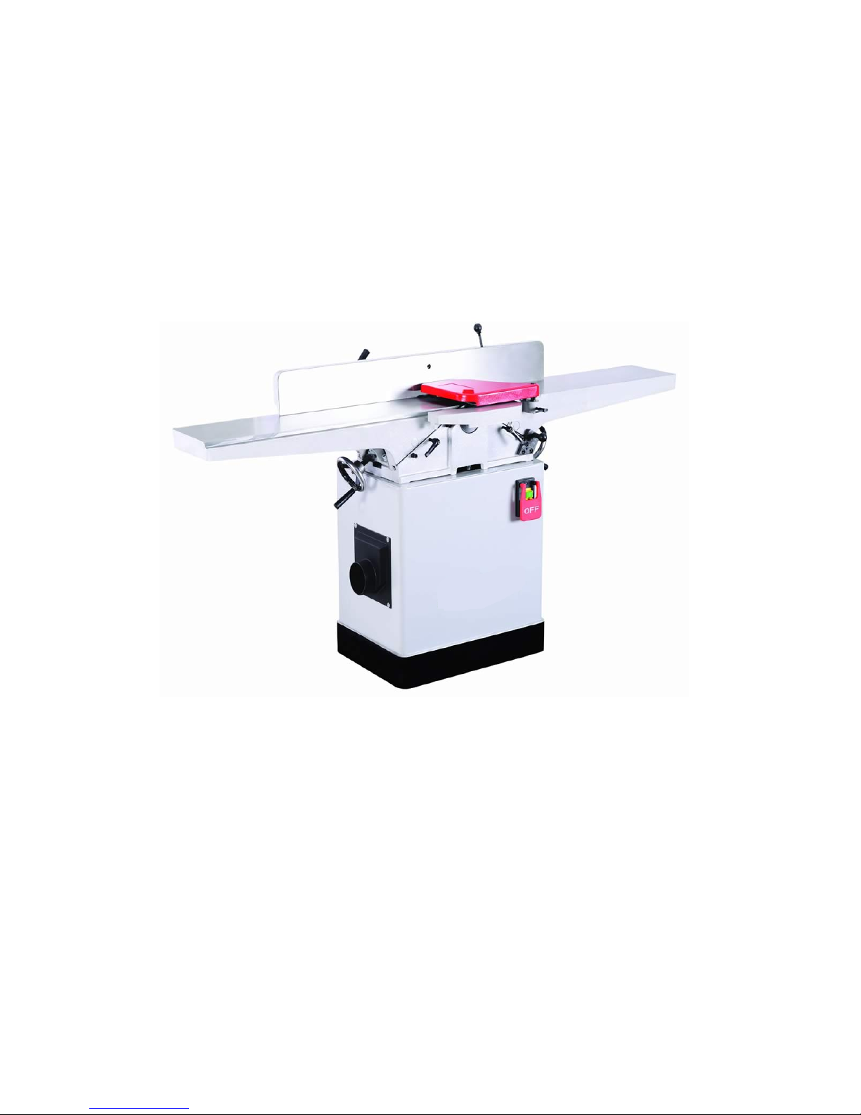
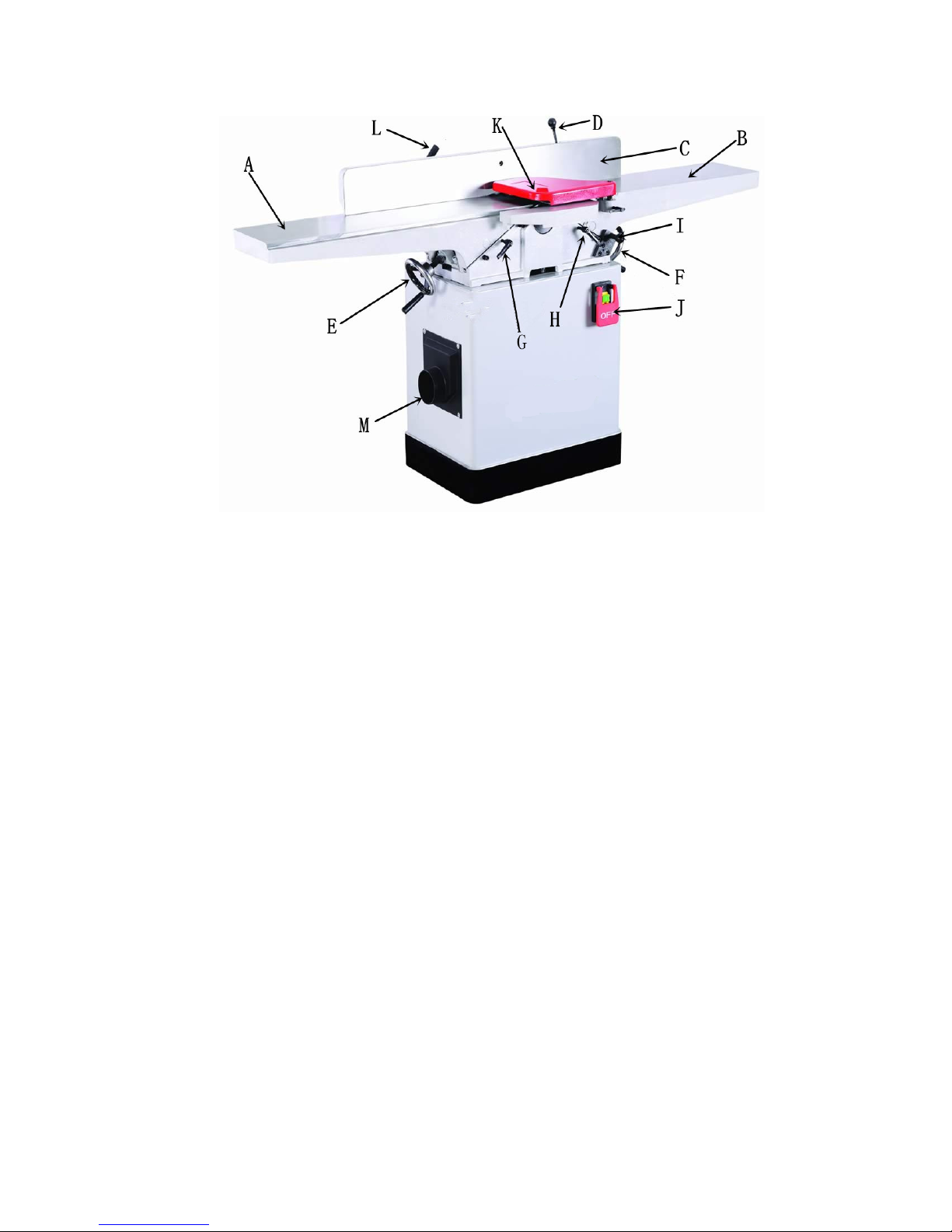
Identification
......................2
2
Table of Contents ..............................................................................................................
Table of Contents
Warning........................................................................................................................
.............. 5
Specifications .................................................................................................................
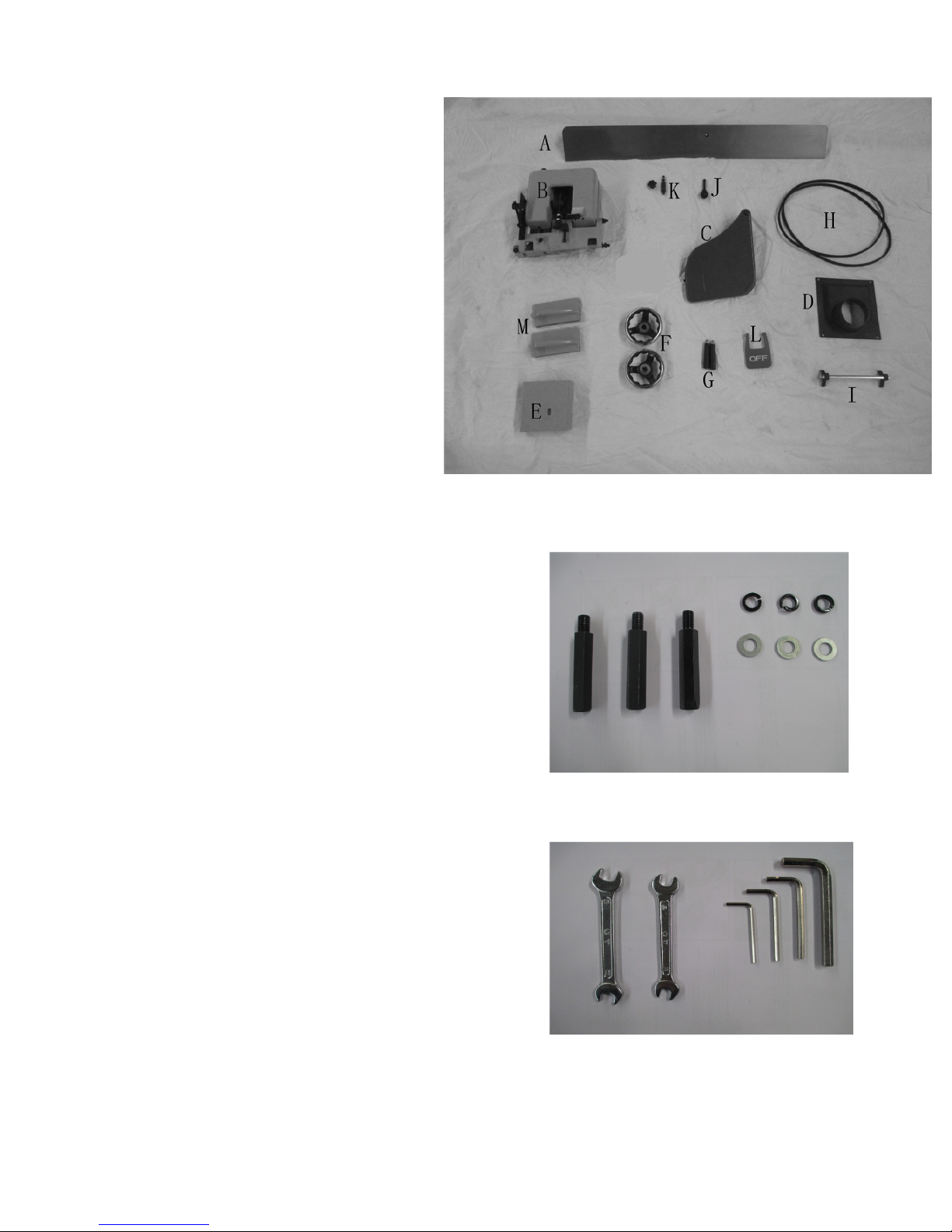
Unpacking and Cleanup
Unpacking and Cleanup
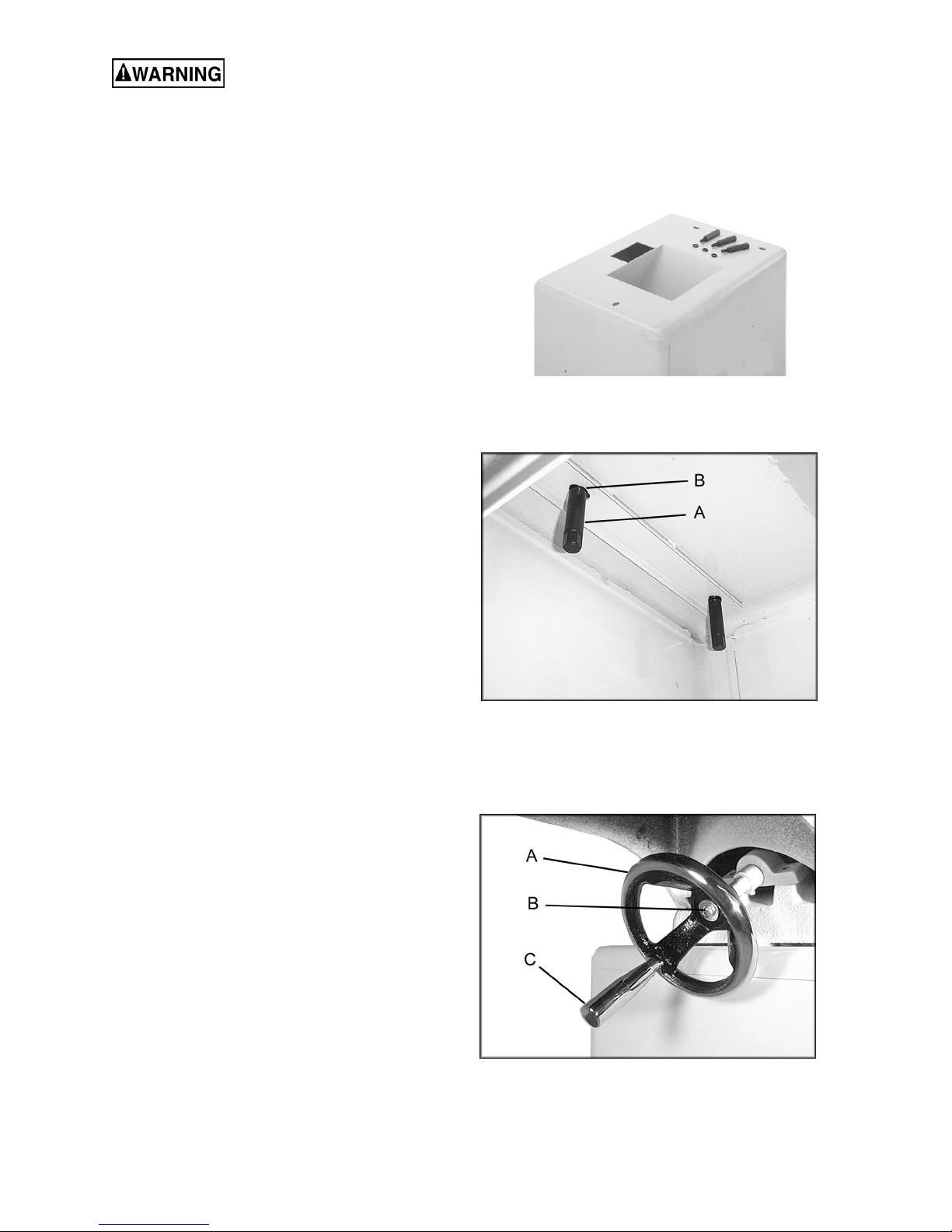
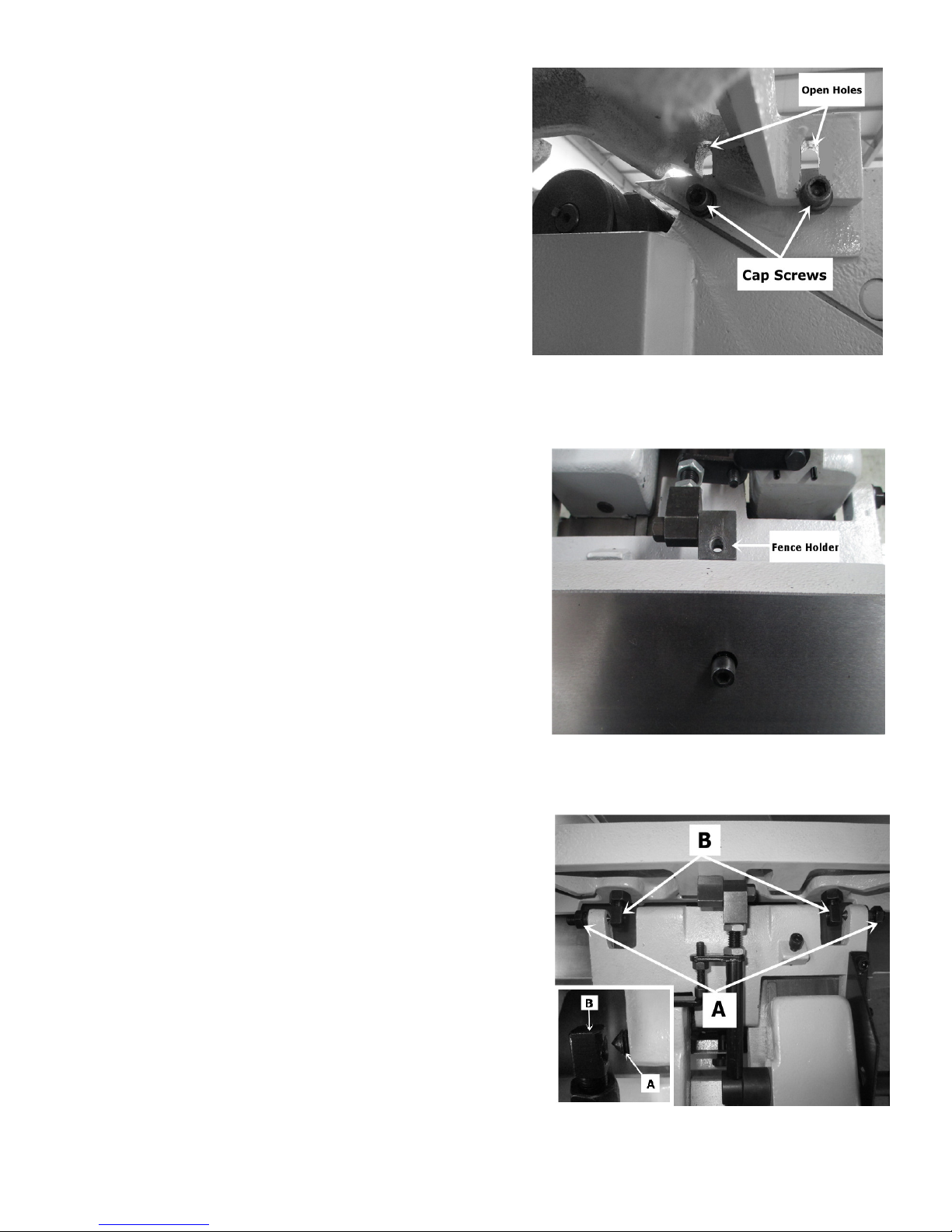
Installing Bed to Stand ........................................................................................................
Installing Handwheels
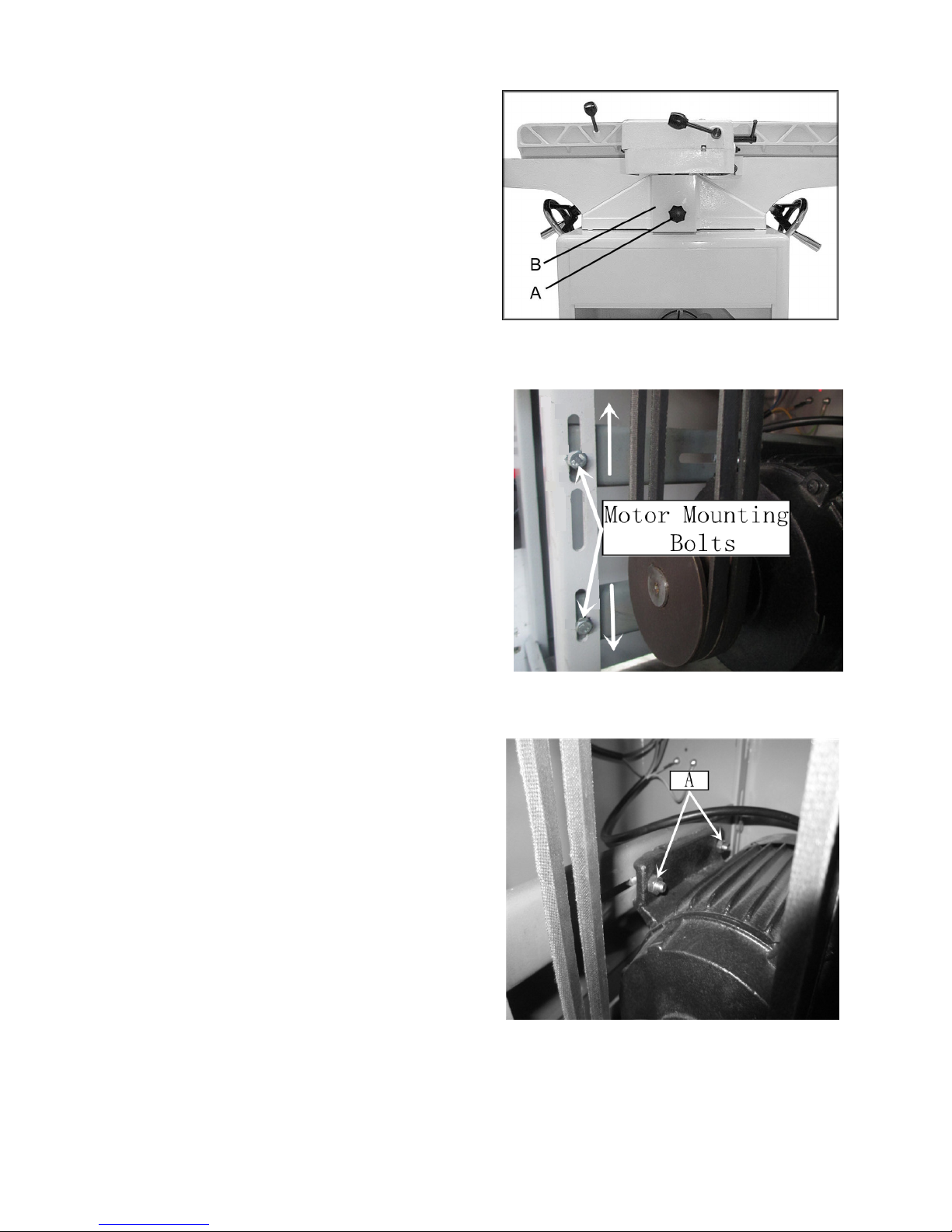
Installing V-Belts .............................................................................................................
Installing Cutterhead Guard
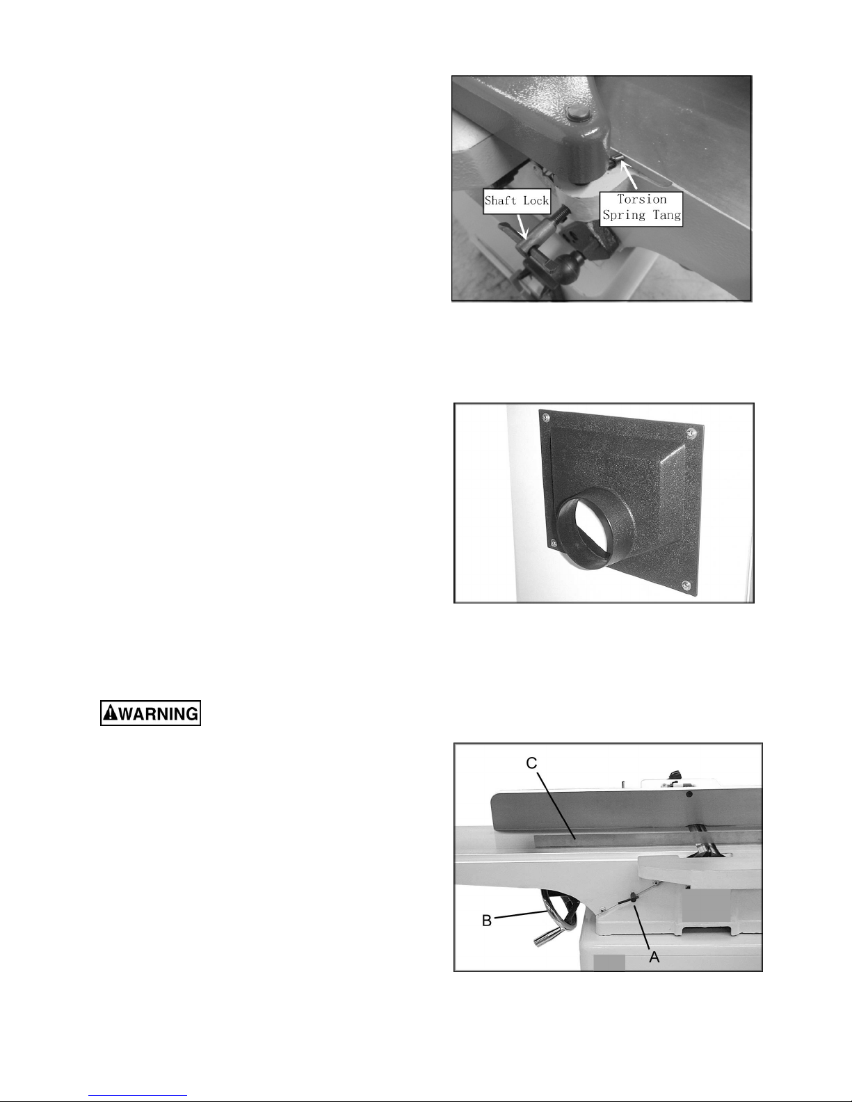
Installing Dust Chute..........................................................................................................
Adjustments ....................................................................................................................
90° Fence Adjustment...........................................................................................................
45° Fence Adjustment........................................................................................................................ 12
Removing and Replacing Knives
Replacing or Rotating Knife Inserts
Gib Adjustment .................................................................................................................
Operation ......................................................................................................................
Jointing Warped Material
Direction of Grain.............................................................................................................
Bevel Cut......................................................................................................................
Taper Cut..............................................................................................................................
Rabbet Cut ...............................................................................................................................
Maintenance...............................................................................................................................
Lubrication ...............................................................................................................................
Blade Care...............................................................................................................................
Sharpening the Knives
Cutterhead Removal
Instakking Fende To Fence Carriage.............................