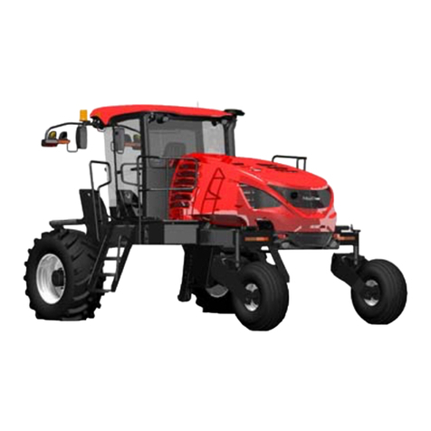
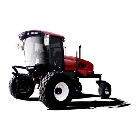
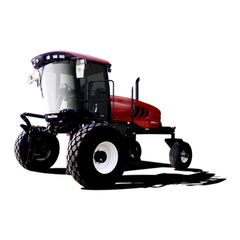
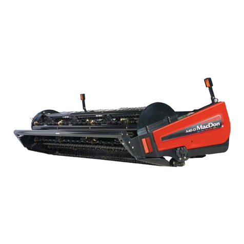
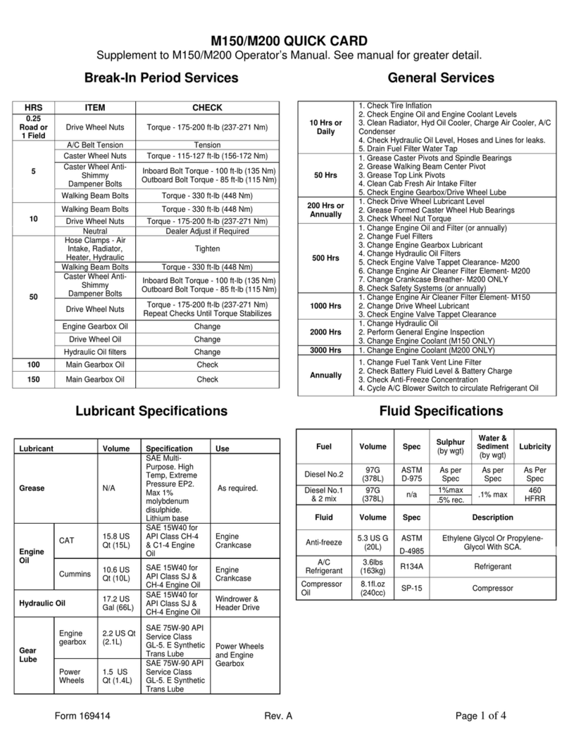
MacDon M1240 User manual

The harvesting specialists.
M1240
Self-Propelled Windrower
Unloading and Assembly Instructions (North America)
214056 Revision A
2017 Model Year
Original Instruction

M1240 Self-Propelled Windrower, featuring Dual Direction®and Crossflex™rear suspension
Published November 2016

Introduction
This manual contains unloading, assembly, and predelivery information for the MacDon M1240 Self-Propelled
Windrower, which when coupled with one of MacDon’s auger or draper headers, provides a package designed to
cut and lay a variety of grain, hay, and specialty crops in windrows.
The M1240 Windrower is Dual Direction®, meaning that the windrower can be driven in the cab-forward or the
engine-forward mode. Right and left designations are determined by the operator’s position facing the direction
of travel. This manual uses the terms “right cab-forward”, “left cab-forward”, “right engine-forward”, and “left
engine-forward” when referencing specific locations on the machine.
The ignition keys were shipped with the shipping documents and are used to lock the cab doors and tool box
compartment.
NOTE:
Keep your MacDon publications up-to-date. The most current version can be downloaded from our website
(www.macdon.com) or from our Dealer-only site (https://portal.macdon.com) (login required).
214056 iRevision A


TABLE OF CONTENTS
Introduction...................................................................................................................................... i
1 Safety.................................................................................................................................................... 1
1.1 Signal Words................................................................................................................................... 1
1.2 General Safety ................................................................................................................................ 2
1.3 Battery Safety.................................................................................................................................. 4
1.4 Safety Signs.................................................................................................................................... 5
2 Unloading the Windrower...................................................................................................................... 7
2.1 Using One Forklift to Unload Windrower............................................................................................7
3 Assembling the Windrower................................................................................................................... 9
3.1 Repositioning Right Leg................................................................................................................... 9
3.2 Installing Drive Wheels....................................................................................................................11
3.3 Installing Caster Wheels................................................................................................................. 12
3.4 Repositioning Walking Beam and Installing Caster Wheel Shocks..................................................... 13
3.5 Lowering Steps.............................................................................................................................. 16
3.6 Installing Windshield Access Step................................................................................................... 17
3.7 Positioning Mirror Arms.................................................................................................................. 18
3.8 Installing Slow Moving Vehicle (SMV) Signs .................................................................................... 19
3.9 Replacing Speed Identification Symbol (SIS) Decal (US Only).......................................................... 20
3.10 Installing Rear Ballast Package ...................................................................................................... 21
3.11 Lubricating the Windrower.............................................................................................................. 25
3.11.1 Lubrication Procedure ............................................................................................................ 25
3.11.2 Lubrication Points................................................................................................................... 25
3.12 Connecting Batteries...................................................................................................................... 26
3.13 Starting the Engine........................................................................................................................ 28
4 Attaching Headers to M1 Series Windrower........................................................................................ 31
4.1 A40 D Auger Header...................................................................................................................... 31
4.1.1 Attaching an A40 D Auger Header........................................................................................... 31
4.1.2 Connecting A40 D Hydraulics.................................................................................................. 36
4.1.3 Detaching an A40 D Auger Header.......................................................................................... 38
4.2 D1X or D1XL Series Header........................................................................................................... 43
4.2.1 Attaching Draper Header Supports.......................................................................................... 43
4.2.2 Attaching a D1X or D1XL Series Header.................................................................................. 43
4.2.3 Connecting D1X or D1XL Series Hydraulics............................................................................. 49
4.2.4 Detaching a D1X or D1XL Series Header................................................................................. 52
4.3 R85 16-Foot Header...................................................................................................................... 57
4.3.1 Attaching an R85 16-Foot Header........................................................................................... 57
4.3.2 Connecting R85 16-Foot Header Hydraulics ............................................................................ 63
4.3.3 Detaching R85 16-Foot Header............................................................................................... 65
5 Performing Predelivery Checks........................................................................................................... 69
5.1 Completing Predelivery Checklist.................................................................................................... 69
5.1.1 Recording Serial Numbers...................................................................................................... 69
5.1.2 Checking and Adding Wheel Drive Lubricant Level................................................................... 70
5.1.3 Checking Tire Pressures......................................................................................................... 70
5.1.4 Checking Engine Air Intake..................................................................................................... 72
5.1.5 Checking Engine Oil Level...................................................................................................... 72
5.1.6 Checking and Adding Hydraulic Oil.......................................................................................... 73
5.1.7 Checking Fuel Separator........................................................................................................ 74
5.1.8 Checking Engine Coolant Level............................................................................................... 74
5.1.9 Checking Engine Gearbox Lubricant Level and Adding Lubricant.............................................. 76
5.1.10 Checking Air Conditioning (A/C) Compressor Belts................................................................... 76
5.1.11 Checking Operating Safety System......................................................................................... 76
5.2 Performing Operational Checks...................................................................................................... 78
5.2.1 Checking Harvest Performance Display (HPT)......................................................................... 78
214056 iii Revision A
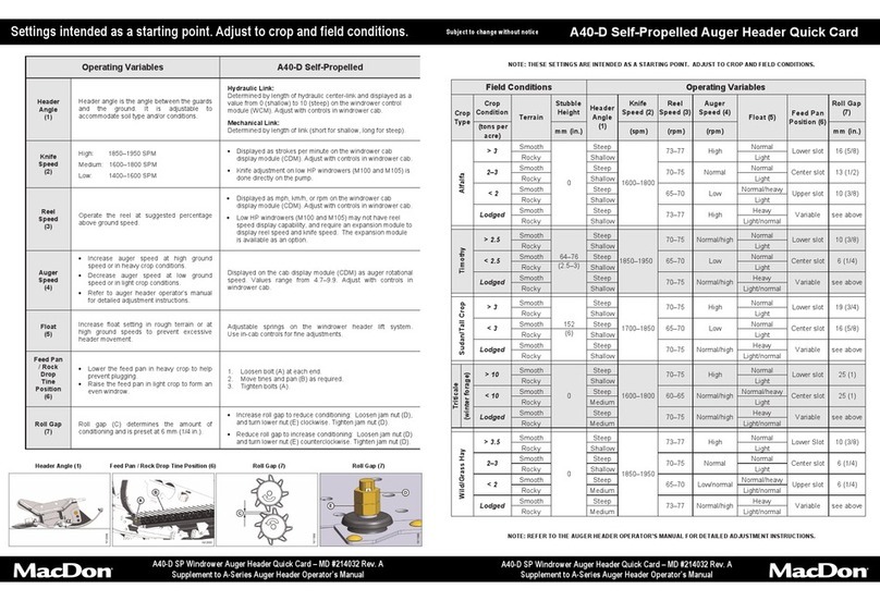
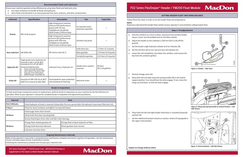
TABLE OF CONTENTS
Navigating the Harvest Performance Tracker.................................................................... 79
Setting Display Language and Units of Measure............................................................... 80
Setting Display Time and Date......................................................................................... 81
Setting Windrower Tire Size ............................................................................................ 82
Checking Header Settings............................................................................................... 82
5.2.2 Checking Engine Speed ......................................................................................................... 83
5.2.3 Checking Exterior Lights......................................................................................................... 84
5.2.4 Checking Horn....................................................................................................................... 87
5.2.5 Checking Interior Lights.......................................................................................................... 88
5.2.6 Checking Air Conditioning and Heater ..................................................................................... 88
5.3 Checking Manuals......................................................................................................................... 90
5.4 Performing Final Steps................................................................................................................... 91
6 Reference............................................................................................................................................ 93
6.1 Lubricants, Fluids, and System Capacities....................................................................................... 93
6.2 Fuel Specifications.........................................................................................................................95
6.3 Torque Specifications..................................................................................................................... 96
6.3.1 Metric Bolt Specifications........................................................................................................ 96
6.3.2 Metric Bolt Specifications Bolting into Cast Aluminum............................................................... 99
6.3.3 O-Ring Boss (ORB) Hydraulic Fittings (Adjustable)..................................................................100
6.3.4 O-Ring Boss (ORB) Hydraulic Fittings (Non-Adjustable) ..........................................................102
6.3.5 O-Ring Face Seal (ORFS) Hydraulic Fittings...........................................................................103
6.3.6 Tapered Pipe Thread Fittings .................................................................................................105
6.4 Conversion Chart..........................................................................................................................106
6.5 Definitions....................................................................................................................................107
Predelivery Checklist ....................................................................................................................111
214056 ivRevision A

1Safety
1.1 Signal Words
Three signal words, DANGER, WARNING, and CAUTION, are used to alert you to hazardous situations. The
appropriate signal word for each situation has been selected using the following guidelines:
DANGER
Indicates an imminently hazardous situation that, if not avoided, will result in death or serious injury.
WARNING
Indicatesapo
tentially hazardous situation that, if not avoided, could result in death or serious injury. It
mayalsobeuse
d to alert against unsafe practices.
CAUTION
Indicates a potentially hazardous situation that, if not avoided, may result in minor or moderate injury. It
may be used to alert against unsafe practices.
214056 1Revision A

SAFETY
1.2 General Safety
CAUTION
The following are general farm safety precautions
that should be part of your operating procedure for
all types of machinery.
Protect yourself.
• When assembling, operating, and servicing machinery,
wear all protective clothing and personal safety devices
that could be necessary for job at hand. Do NOT take
chances. You may need the following:
• Hard hat
• Protective footwear with slip resistant soles
• Protective glasses or goggles
• Heavy gloves
• Wet weather gear
• Respirator or filter mask
Figure 1.1: Safety Equipment
• Be aware that exposure to loud noises can cause
hearing impairment or loss. Wear suitable hearing
protection devices such as ear muffs or ear plugs to
help protect against objectionable or loud noises.
Figure 1.2: Safety Equipment
•Provideafirst aid kit for use in case of emergencies.
•Keepafire extinguisher on the machine. Be sure fire
extinguisher is properly maintained. Be familiar with its
proper use.
• Keep young children away from machinery at all times.
• Be aware that accidents often happen when Operator
istiredorinahurry.Taketimetoconsidersafestway.
Never ignore warning signs of fatigue.
Figure 1.3: Safety Equipment
214056 2Revision A

SAFETY
•Wearclose-fitting clothing and cover long hair. Never
wear dangling items such as scarves or bracelets.
• Keep all shields in place. NEVER alter or remove safety
equipment. Make sure driveline guards can rotate
independently of shaft and can telescope freely.
• Use only service and repair parts made or approved
by equipment manufacturer. Substituted parts may not
meet strength, design, or safety requirements.
Figure 1.4: Safety around Equipment
• Keep hands, feet, clothing, and hair away from moving
parts. NEVER attempt to clear obstructions or objects
from a machine while engine is running.
•DoNOT modify machine. Unauthorized modifications
may impair machine function and/or safety. It may also
shorten machine’s life.
• To avoid bodily injury or death from unexpected startup
of machine, ALWAYS stop engine and remove key from
ignition before leaving operator’s seat for any reason.
Figure 1.5: Safety around Equipment
• Keep service area clean and dry. Wet or oily floors are
slippery. Wet spots can be dangerous when working
with electrical equipment. Be sure all electrical outlets
and tools are properly grounded.
• Keep work area well lit.
• Keep machinery clean. Straw and chaff on a hot
engine is a fire hazard. Do NOT allow oil or grease to
accumulate on service platforms, ladders, or controls.
Clean machines before storage.
•NEVER use gasoline, naphtha, or any volatile material
for cleaning purposes. These materials may be toxic
and/or flammable.
• When storing machinery, cover sharp or extending
components to prevent injury from accidental contact. Figure 1.6: Safety around Equipment
214056 3Revision A

SAFETY
1.3 Battery Safety
WARNING
• Keep all sparks and flames away from batteries, as
a gas given off by electrolyte is explosive.
• Ventilate when charging in enclosed space.
Figure 1.7: Safety around Batteries
WARNING
• Wear safety glasses when working near batteries.
• Do NOT tip batteries more than 45° to avoid
electrolyte loss.
• Battery electrolyte causes severe burns. Avoid
contact with skin, eyes, or clothing.
• Electrolyte splashed into eyes is extremely
dangerous. Should this occur, force eye open, and
flood with cool, clean water for five minutes. Call
a doctor immediately.
• If electrolyte is spilled or splashed on clothing or
body, neutralize it immediately with a solution of
baking soda and water, then rinse with clear water.
Figure 1.8: Safety around Batteries
WARNING
• To avoid injury from spark or short circuit,
disconnect battery ground cable before servicing
and part of electrical system.
• Do NOT operate engine with alternator or battery
disconnected. With battery cables disconnected
and engine running, a high voltage can be
built up if terminals touch frame. Anyone
touching frame under these conditions would be
severely shocked.
• When working around storagebatteries, remember
that all of the exposed metal parts are live. Never
layametalobjectacrossterminalsbecauseaspark
or short circuit will result.
• Keep batteries out of reach of children.
Figure 1.9: Safety around Batteries
214056 4Revision A

SAFETY
1.4 Safety Signs
• Keep safety signs clean and legible at all times.
• Replace safety signs that are missing or
become illegible.
• If original parts on which a safety sign was installed
are replaced, be sure repair part also bears current
safety sign.
• Safety signs are available from your MacDon Dealer.
Figure 1.10: Operator’s Manual Decal
214056 5Revision A


2 Unloading the Windrower
2.1 Using One Forklift to Unload Windrower
CAUTION
Equipment used for unloading must meet or exceed the specified requirements. Using inadequate
equipment may result in chain breakage, vehicle tipping, or machine damage.
Table 2.1 Lifting Vehicle Requirements
Minimum Capacity17037 kg (15,500 lb.)
Minimum Fork Length 198.1 cm (78 in.)
IMPORTANT:
Forklifts are normally rated for a load located 610 mm (24 in.) ahead of the back end of the forks. To obtain forklift
capacity at 122.2 cm (48 in.), check with your forklift distributor.
1. Move the trailer onto level ground and block the
trailer wheels.
2. Set forklift tines to the widest possible setting.
CAUTION
Ensure forks do not contactorliftonfueltank(A)or
engine oil pan (B) (not shown).
3. Position forklift on left or right side of trailer, and
position forks (C) under windrower frame with the fuel
tank (A) between the forks.
NOTE:
The windrower’s center of gravity is
approximately 157.5 cm (62 in.) rearwards from
the center of the drive wheel.
Figure 2.1: Windrower on Trailer
WARNING
Ensure the forks extend beyond the far side of the frame.
4. Lift until windrower is clear of the trailer deck.
5. Back forklift slowly away from trailer until the windrower is clear of the trailer deck.
6. Lower unit slowly to the ground. If the ground is soft, place wooden blocks under the front shipping stands.
7. Carefully back forklift away from windrower.
8. Check windrower for shipping damage, and check shipment for missing parts.
1. At 122.2 cm (48 in.) from back end of forks.
214056 7Revision A


3 Assembling the Windrower
Perform all procedures in this chapter in the order in which they are listed.
3.1 Repositioning Right Leg
The right (cab-forward) leg requires repositioning from shipping to field configuration.
CAUTION
Do NOT open the right cab-forward door when the right leg is in shipping configuration. If glass door
contacts the leg, it may result in broken glass door and/or damaged door seal.
1. Remove two bolts (A), washers, and nuts from frame.
Figure 3.1: Windrower Frame
2. Support the front of the windrower with a stand (A) (or
equivalent) so the right leg is off the ground.
3. Position jack (B) under the right leg and slightly raise
thejacktotakesomeweightofftheleg.
Figure 3.2: Right Leg
214056 9Revision A

ASSEMBLING THE WINDROWER
4. Adjust jack height until pin (A)is loose. Extract pin from
front of frame with a slide hammer (MD #209816) (B)
(tool required due to limited space in front of fuel tank).
Instructions are included with the tool.
NOTE:
Removing the pins will be difficult if the jack is not
properly positioned to take the weight off the leg.
5. Repeat for second pin.
Figure 3.3: Windrower Frame
6. Move leg outwards to expose one hole (A).
7. Align holes at pin locations and reinstall pins (B). If
necessary, tap in pin with a rubber mallet, or install bolt
and washer in pin if using a metal hammer. Adjust jack
to prevent damage to the outer edges of the pins.
Figure 3.4: Windrower Frame
8. Secure pins with bolts (A), washers, and nuts. Torque
nuts to 136 N·m (100 ft·lbf).
9. Lower jack and move it from work area.
Figure 3.5: Windrower Frame
214056 10 Revision A

ASSEMBLING THE WINDROWER
3.2 Installing Drive Wheels
1. Clean mount surface on wheel drive and rim.
2. Position drive wheel (A) against the wheel drive
hub(B)sotheairvalve(C)isontheoutsideandthe
tire tread (D) points forward with the windrower in
cab-forward orientation.
NOTE:
For turf tires (diamond tread pattern), be sure
arrow on sidewall points in forward rotation with
windrower in cab-forward mode.
Figure 3.6: Drive Wheel Assembly
CAUTION
Use a lifting device capable of supporting a minimum
of 907 kg (2000 lb.) to lift the wheel assembly.
3. Lift wheel onto hub using a lifting device.
4. Lower lifting device.
5. Line up the holesin the rim with the studs on the wheel
drive hub and install wheel nuts (A).
IMPORTANT:
To avoid damage to wheel rims and studs,
tighten nuts by hand. Threads must be clean
and dry. Do NOT apply lubricant or anti-seize
compound. Do NOT use an impact gun. Do
NOT overtighten the wheel nuts.
6. Torque drive wheel nuts to 510 N·m (375 ft·lbf) using
the tightening sequence shown.
IMPORTANT:
Use only manufacturer-specified nuts
(MD #205397).
7. Repeat tightening sequence two additional times,
ensuring the specified torque is achieved each time.
8. Repeat torque procedure every hour of operation
until two consecutive checks confirm that there is no
movement of the nuts.
Figure 3.7: Drive Wheel Nuts
214056 11Revision A

ASSEMBLING THE WINDROWER
3.3 Installing Caster Wheels
Some shipping configurations come with caster wheels removed. Follow this procedure to install caster wheels
if requried.
1. Support rear of windrower on a stand so that it
is approximately level. Stand must be capable of
supporting a minimum of 2630 kg (5800 lb.).
2. Remove banding and blocking (A) securing walking
beam to frame.
Figure 3.8: Walking Beam
3. Retrieve caster wheel assemblies (A) from shipment.
4. Remove retaining ring (B), arm (C), key (D), and one
flat washer (E) from caster spindle. Leave two flat
washers on spindle. Loosen nut (F) if necessary.
5. Attachaslingtocasterassemblyandtoasuitable
lifting device.
Figure 3.9: Caster
6. Tilt walking beam (A) and maneuver caster
assembly (B) so that spindle can be installed onto
walking beam.
7. Install the flat washer (C) onto the spindle.
8. Install arm (D) with key (E) onto spindle, ensuring that
armispositionedsothereisnoclearanceatthetopand
bottom of the walking beam extension. Tighten nut (F)
and torque to 190–200 N·m (140–147 ft·lbf).
9. Install retaining ring (G).
10. Remove sling from caster assembly.
11. Repeat Steps 4, page 12 to 10, page 12 for second
caster assembly. Figure 3.10: Walking Beam
214056 12Revision A

ASSEMBLING THE WINDROWER
3.4 Repositioning Walking Beam and Installing Caster
Wheel Shocks
A narrow walking beam tread width is better suited for smaller headers because it allows more space for the uncut
crop and provides more maneuverability around poles, irrigation inlets, and other obstacles. A wider walking beam
tread width reduces runover in heavy crops that produce large windrows.
1. Support rear of windrower on a stand. Stand must be
capable of supporting 2630 kg (5800 lb.).
2. Remove four bolts and washers (A), shock support
brackets (B), and slow moving vehicle (SMV) sign
support bracket (C) from walking beam.
3. Retain hardware and support brackets (B) and (C) for
installation later.
NOTE:
There is one SMV support bracket (C)
preinstalled on shock support brackets (B) at the
left cab-forward walking beam.
Figure 3.11: Walking Beam
4. If not done, remove banding and blocking (A) securing
walking beam to frame.
Figure 3.12: Walking Beam
5. Pull walking beam extension (A) out to desired position
and line up bolt holes. Rotate the caster so the wheel
is parallel to the walking beam to assist with moving
the extensions.
6. Install two M24 x 60 bolts and washers (B) at
inboard hole locations on backside of beam and two
M24 x 60 bolts and washers (C) on bottom of beam.
Do not tighten.
Figure 3.13: Walking Beam Extension
214056 13 Revision A

ASSEMBLING THE WINDROWER
7. Place support brackets (A) onto walking beam as
shown and secure with two M24 x 60 bolts coated with
anti-seize compound and M24 flat washers (B). Do
NOT fully tighten.
Figure 3.14: Anti-Shimmy Brackets
8. Tighten bolts as follows:
a. Snug bottom bolts (A), then snug back bolts (B).
b. Torque back bolts (B) to
745–770 N·m (549–568 ft·lbf).
c. Torque bottom bolts (A) to
745–770 N·m (549–568 ft·lbf).
IMPORTANT:
Torque bolts after first 5 hours of operation, and
then again after 10 hours.
Figure 3.15: Walking Beam Bolts
9. Repeat Steps 2, page 13 to 8, page 14 at opposite
end of walking beam, ensuring that casters are spaced
equally from center of windrower.
Figure 3.16: Walking Beam Adjustment
214056 14Revision A
Other manuals for M1240
2
Table of contents
Other MacDon Farm Equipment manuals

MacDon
MacDon R113 User manual

MacDon
MacDon FD75 User manual

MacDon
MacDon HC10 Guide

MacDon
MacDon A30-S User manual

MacDon
MacDon M155 User manual

MacDon
MacDon D65 User manual

MacDon
MacDon FlexDraper FD1 Series User manual

MacDon
MacDon D65 User manual

MacDon
MacDon R216 SP User manual

MacDon
MacDon M155 User manual