MacDon R216 User manual

R216
Rotary Disc Header for Windrowers
Unloading and Assembly Instructions
215028 Revision A
Original Instruction
The harvesting specialists.

R216 Rotary Disc Header
1030661
Published September 2019.
© 2019 MacDon Industries, Ltd.
The information in this publication is based on the information available and in effect at the time of printing. MacDon
Industries, Ltd. makes no representation or warranty of any kind, whether expressed or implied, with respect to the
information in this publication. MacDon Industries, Ltd. reserves the right to make changes at any time without notice.

Introduction
This document describes the unloading, setup, and predelivery requirements for the MacDon R216 Rotary Disc Header.
To ensure your customers receive all of the performance and safety benefits from this product, carefully follow the
unloading and assembly procedure from the beginning through to completion.
Retain this instruction for future reference.
Conventions
The following conventions are used in this document:
•Right and left are determined from the operator’s position. The front of the rotary disc header faces the crop.
•Unless otherwise noted, use the standard torque values provided in this manual.
Carefully read all the material provided before attempting to unload, assemble, or use the machine.
NOTE:
Keep your MacDon publications up-to-date. The most current version can be downloaded from our website
(www.macdon.com) or from our Dealer-only site (https://portal.macdon.com) (login required).
This instruction is currently available in English only.
215028 iRevision A

Summary of Changes
At MacDon, we’re continuously making improvements, and occasionally these improvements affect product
documentation. The following list provides an account of major changes from the previous version of this document.
Section Summary of Change
Internal Use
Only
Throughout Changed hanging drum to suspended drum Tech Pubs
—Removed Adjustable Gauge roller kit instructions Tech Pubs
—Removed Adjustable Skid Shoes kit instructions Tech Pubs
3.1 Removing Shipping Supports, page 9 Updated images and procedure, added torque value E58869
3.4 Removing Shipping Stands, page 14 Added missing steps Tech Pubs
4.1.1 Assembling and Installing Forming
Shield, page 19 Updated images and procedure Product
Support
4.1.2 Routing Electrical Harness, page 26 Updated images and procedure Tech Pubs
4.1.4 Connecting Rotary Disc Header
Hydraulics Using Quick Couplers –M1240
Windrowers, page 34
Added note Product
Support
4.1.5 Connecting Rotary Disc Header
Hydraulics Using Hard Plumbing, page 36 Added note Product
Support
4.1.4 Connecting Rotary Disc Header
Hydraulics Using Quick Couplers –M1240
Windrowers, page 34
Updated the procedure ECN 58681
4.1.8 Unpacking the Curtain, page 41 Update images and procedure E58886
6.1 Lubrication Locations, page 46 Updated driveline positions ECN 58852
7.3.1 Checking Suspended Drum Drive,
page 54 Updated images Tech Pubs
7.4.1 Checking Feed Roll Drive, page 55 Updated images and text ECN 31050
8.1 Starting the Engine, page 65 Added reference topic Tech Pubs
8.2 Engaging and Disengaging Header
Safety Props, page 69 Added reference topic Tech Pubs
8.3 Leveling the Header, page 71 Added reference topic Tech Pubs
8.4 Closing Driveshields, page 74 Added reference topic Tech Pubs
8.5 Opening Driveshields, page 75 Added reference topic Tech Pubs
8.6 Closing Cutterbar Curtain, page 77 Added reference topic Tech Pubs
8.7 Opening Cutterbar Curtain, page 78 Added reference topic Tech Pubs
8.8 Recommended Lubricants, page 79 Updated oil quantity Tech Pubs
215028 ii Revision A

215028 iii Revision A
Introduction ................................................................................................................................................i
Summary of Changes....................................................................................................................................ii
Chapter 1: Safety ........................................................................................................................................ 1
1.1 Signal Words .........................................................................................................................................1
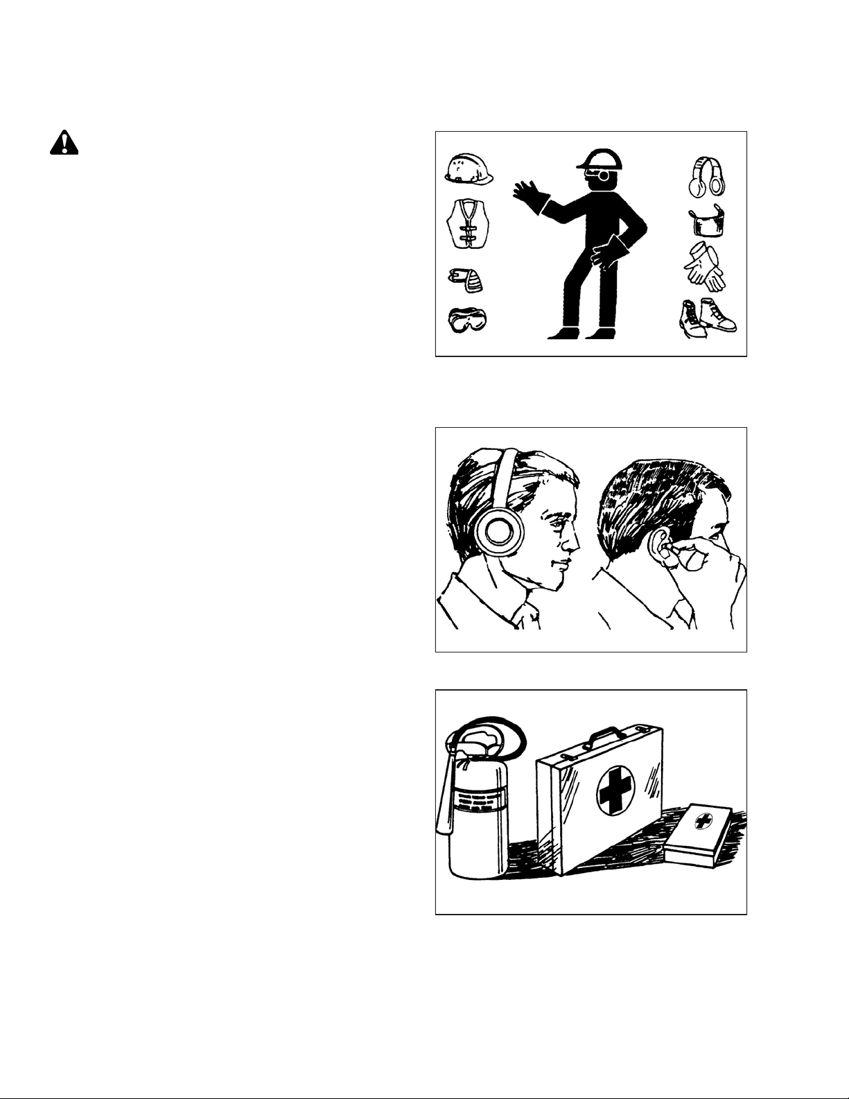
1.2 General Safety .......................................................................................................................................2
1.3 Welding Precaution ................................................................................................................................4
1.4 Safety Signs ...........................................................................................................................................5
Chapter 2: Unloading the Header from a Trailer ...................................................................................... 7
Chapter 3: Assembling the Header ............................................................................................................ 9
3.1 Removing Shipping Supports ....................................................................................................................9
3.2 Lowering the Header............................................................................................................................. 11
3.3 Unpacking Hydraulic Hoses and Electrical Harness –M1240......................................................................... 13
3.4 Removing Shipping Stands ..................................................................................................................... 14
3.5 Installing Manual Rear Deflectors ............................................................................................................ 17
Chapter 4: Attaching Rotary Disc Header to M1240 Windrower........................................................... 19
4.1 Attaching Header to M1240 ................................................................................................................... 19
4.1.1 Assembling and Installing Forming Shield ......................................................................................... 19
4.1.2 Routing Electrical Harness ............................................................................................................. 26
4.1.3 Attaching Rotary Disc Header......................................................................................................... 29
4.1.4 Connecting Rotary Disc Header Hydraulics Using Quick Couplers –M1240 Windrowers............................ 34
4.1.5 Connecting Rotary Disc Header Hydraulics Using Hard Plumbing .......................................................... 36
4.1.6 Restoring Float for Rotary Disc Header............................................................................................. 38
4.1.7 Calibrating Windrower Knife Drive on the Harvest Performance Tracker Display ..................................... 40
4.1.8 Unpacking the Curtain .................................................................................................................. 41
Chapter 5: Installing Options.................................................................................................................... 43
Chapter 6: Lubricating the Rotary Disc Header....................................................................................... 45
6.1 Lubrication Locations ............................................................................................................................ 46
Chapter 7: Performing Predelivery Checks.............................................................................................. 49
7.1 Conditioner Drive Belt ........................................................................................................................... 49
7.1.1 Inspecting Conditioner Drive Belt.................................................................................................... 49
7.1.2 Adjusting Conditioner Drive Belt ..................................................................................................... 50
7.2 Header Float........................................................................................................................................ 52
7.2.1 Checking Float............................................................................................................................. 52
7.2.2 Setting the Float .......................................................................................................................... 52
7.3 Suspended Drum Drive.......................................................................................................................... 54
7.3.1 Checking Suspended Drum Drive .................................................................................................... 54
7.4 Feed Roll Drive..................................................................................................................................... 55
TABLE OF CONTENTS

215028 iv Revision A
7.4.1 Checking Feed Roll Drive ............................................................................................................... 55
7.5 Checking and Adding Conditioner Roll Timing Gearbox Oil ........................................................................... 56
7.6 Checking and Adding Oil in Header Drive Gearbox...................................................................................... 57
7.7 Checking and Adding Lubricant in Cutterbar .............................................................................................. 59
7.8 Checking Lights .................................................................................................................................... 62
7.9 Checking Manuals................................................................................................................................. 63
7.10 Running up the Header ........................................................................................................................ 64
Chapter 8: Reference ................................................................................................................................ 65
8.1 Starting the Engine ............................................................................................................................... 65
8.2 Engaging and Disengaging Header Safety Props ......................................................................................... 69
8.3 Leveling the Header .............................................................................................................................. 71
8.4 Closing Driveshields .............................................................................................................................. 74
8.5 Opening Driveshields ............................................................................................................................ 75
8.6 Closing Cutterbar Curtain....................................................................................................................... 77
8.7 Opening Cutterbar Curtain ..................................................................................................................... 78
8.8 Recommended Lubricants...................................................................................................................... 79
8.9 Torque Specifications ............................................................................................................................ 80
8.9.1 Metric Bolt Specifications .............................................................................................................. 80
8.9.2 Metric Bolt Specifications Bolting into Cast Aluminum ........................................................................ 82
8.9.3 O-Ring Boss Hydraulic Fittings –Adjustable ...................................................................................... 83
8.9.4 O-Ring Boss Hydraulic Fittings –Non-Adjustable................................................................................ 85
8.9.5 O-Ring Face Seal Hydraulic Fittings.................................................................................................. 86
8.9.6 Tapered Pipe Thread Fittings.......................................................................................................... 87
8.10 Conversion Chart ................................................................................................................................ 88
8.11 Definitions......................................................................................................................................... 89
Predelivery Checklist ................................................................................................................................ 91
TABLE OF CONTENTS

215028 1Revision A
Chapter 1: Safety
1.1 Signal Words
Three signal words, DANGER,WARNING, and CAUTION, are used to alert you to hazardous situations. Two signal words,
IMPORTANT and NOTE, identify non-safety related information. Signal words are selected using the following guidelines:
DANGER
Indicates an imminently hazardous situation that, if not avoided, will result in death or serious injury.
WARNING
Indicates a potentially hazardous situation that, if not avoided, could result in death or serious injury. It may also be
used to alert against unsafe practices.
CAUTION
Indicates a potentially hazardous situation that, if not avoided, may result in minor or moderate injury. It may be used
to alert against unsafe practices.
IMPORTANT:
Indicates a situation that, if not avoided, could result in a malfunction or damage to the machine.
NOTE:
Provides additional information or advice.

215028 2Revision A
1.2 General Safety
1000004
Figure 1.1: Safety Equipment
CAUTION
The following general farm safety precautions should be part of
your operating procedure for all types of machinery.
Protect yourself when assembling, operating, and servicing
machinery, wear all protective clothing and personal safety
devices that could be necessary for the job at hand. Do NOT
take chances. You may need the following:
•Hard hat
•Protective footwear with slip-resistant soles
•Protective glasses or goggles
•Heavy gloves
•Wet weather gear
•Respirator or filter mask
1000005
Figure 1.2: Safety Equipment
•Be aware that exposure to loud noises can cause hearing
impairment or loss. Wear suitable hearing protection devices
such as earmuffs or earplugs to help protect against loud
noises.
1010391
Figure 1.3: Safety Equipment
•Provide a first aid kit in case of emergencies.
•Keep a properly maintained fire extinguisher on the machine.
Be familiar with its proper use.
•Keep young children away from machinery at all times.
•Be aware that accidents often happen when the Operator is
tired or in a hurry. Take time to consider safest way. NEVER
ignore warning signs of fatigue.
SAFETY

215028 3Revision A
1000007
Figure 1.4: Safety around Equipment
•Wear close-fitting clothing and cover long hair. NEVER wear
dangling items such as scarves or bracelets.
•Keep all shields in place. NEVER alter or remove safety
equipment. Make sure driveline guards can rotate
independently of shaft and can telescope freely.
•Use only service and repair parts made or approved by
equipment manufacturer. Substituted parts may not meet
strength, design, or safety requirements.
1000008
Figure 1.5: Safety around Equipment
•Keep hands, feet, clothing, and hair away from moving parts.
NEVER attempt to clear obstructions or objects from a
machine while the engine is running.
•Do NOT modify the machine. Unauthorized modifications
may impair machine function and/or safety. It may also
shorten the machine’s life.
•To avoid injury or death from unexpected startup of the
machine, ALWAYS stop the engine and remove the key from
the ignition before leaving the operator’s seat for any reason.
1000009
Figure 1.6: Safety around Equipment
•Keep service area clean and dry. Wet and/or oily floors are
slippery. Wet spots can be dangerous when working with
electrical equipment. Be sure all electrical outlets and tools
are properly grounded.
•Keep work area well lit.
•Keep machinery clean. Straw and chaff on a hot engine are
fire hazards. Do NOT allow oil or grease to accumulate on
service platforms, ladders, or controls. Clean machines before
storage.
•NEVER use gasoline, naphtha, or any volatile material for
cleaning purposes. These materials may be toxic and/or
flammable.
•When storing machinery, cover sharp or extending
components to prevent injury from accidental contact.
SAFETY

215028 4Revision A
1.3 Welding Precaution
Welding should never be attempted on the header while it is connected to a windrower.
WARNING
Severe damage to sensitive, expensive electronics can result from welding on the header while it is connected to the
windrower. It can be impossible to know what effect high current could have with regard to future malfunctions or
shorter lifespan. It is very important that welding on the header is not attempted while the header is connected to the
windrower.
If you need to do any welding on the header, it should first be disconnected and removed from the windrower.
If it is unfeasible to disconnect the header from the windrower before attempting welding, refer to the windrower’s
technical manual for welding precautions detailing all electrical components that must be disconnected first for safe
welding.
SAFETY

215028 5Revision A
1.4 Safety Signs
1000694
Figure 1.7: Operator’s Manual Decal
•Keep safety signs clean and legible at all times.
•Replace safety signs that are missing or illegible.
•If the original part on which a safety sign was installed is
replaced, be sure the repair part displays the current
safety sign.
SAFETY


215028 7Revision A
Chapter 2: Unloading the Header from a Trailer
WARNING
To avoid injury to bystanders from being struck by machinery, do NOT allow people to stand in unloading area.
1013855
A
B
C
Figure 2.1: Minimum Lifting Capacity
A - Load Center of Gravity
B - Load Center 1220 mm (48 in.) from Back of Forks
C - Minimum Fork Length 1981 mm (78 in.)
IMPORTANT:
Equipment used for unloading the header must meet or
exceed the requirements specified below. Using inadequate
equipment may result in chain breakage, machine damage,
or the vehicle tipping.
NOTE:
Forklifts are normally rated for a load located 610 mm
(24 in.) ahead of the back end of the forks. To obtain the
forklift capacity at 1220 mm (48 in.), check with your
forklift distributor.
Table 2.1 Lifting Vehicle
Minimum Capacity 3630 kg (8000 lb.)
Minimum Fork Length 198 cm (78 in.)
1028160
Figure 2.2: Lifting Rotary Disc Header off Trailer
1. Remove the hauler’s tie-down straps and chains.
WARNING
Be sure forks are secure before moving away from load. Stand
clear when lifting.
2. Approach the rotary disc header from its underside and
slide the forks under the lifting framework as far as
possible.
IMPORTANT:
If the load is two units wide, take care to avoid contacting
the other machine.
3. Raise the rotary disc header off the deck.

215028 8Revision A
1030662
Figure 2.3: Moving Disc Header with Forklift
4. Back up until the rotary disc header clears the trailer, and
slowly lower it to 150 mm (6 in.) from the ground.
5. Take the rotary disc header to the storage or setup area.
6. Set the rotary disc header down on secure, level ground. Do
NOT lower the header into working position.
7. Check for shipping damage and missing parts.
UNLOADING THE HEADER FROM A TRAILER

215028 9Revision A
Chapter 3: Assembling the Header
Follow each procedure in this chapter in order.
3.1 Removing Shipping Supports
To remove the shipping supports from the cutterbar side of the header, follow these steps:
1030605
A
B
B
B
A
Figure 3.1: Shipping Supports
1. Remove four bolts and nuts (A) from each yellow shipping
support (B).
2. Remove two supports (B)

215028 10 Revision A
1029718
B
B
AA
A
A
A
A
Figure 3.2: Shipping Stand Brace –Right Side Shown,
Left Side Opposite
3. Remove nuts and bolts (A) from the yellow channel and
header supports.
4. Remove yellow braces (B) from the header.
1030604
A
A
BB
Figure 3.3: Plates
5. Remove three bolts and washers (A) holding support
channel (B) onto the header supports.
6. Remove channel (B) from the header.
ASSEMBLING THE HEADER

215028 11 Revision A
3.2 Lowering the Header
Complete the following steps to lower the header into working position after it has been lifted off its shipping trailer and
set down on the ground.
CAUTION
Ensure spreader bar is secured to the forks so that it cannot slide off the forks or towards the mast as the header is
lowered to the ground.
Table 3.1 Lifting Vehicle
Chain Type Overhead lifting quality (1/2 in.)
Minimum Working Load 2270 kg (5000 lb.)
1028066
AA
BB
C
C
Figure 3.4: Block Placement
1. Place wood blocks (A) at a distance of 42 cm (16 1/2 in.) (B)
on the outboard side of each shipping stand (C).
NOTE:
Wood blocks should be 2 x 4 in. and 1–1.5 m (3–5 ft.) in
length.
ASSEMBLING THE HEADER

215028 12 Revision A
1028261
A
B
B
C
Figure 3.5: Spreader Bar Attached to Disc Header
2. Attach spreader bar (A) to forks.
IMPORTANT:
Length of spreader bar must be approximately
457 cm (15 ft.).
3. Approach the header from its underside with the forklift.
4. Attach chains with hooks to the spreader bar (A) and hook
into shipping brackets (B) on both sides of the disc header.
CAUTION
Stand clear when lowering the disc header.
IMPORTANT:
Chain length must be sufficient to provide a minimum
clearance (C) of 1219 mm (48 in.) between the rotary disc
header and the spreader bar.
IMPORTANT:
Do NOT attach chain hooks to the hazard light standards.
5. Raise forks until lift chains are fully tensioned.
1028609
A
B
B
Figure 3.6: Lowering Rotary Disc Header to the
Ground
6. Back up the forklift SLOWLY, and lower the rotary disc
header (A) into working position on the wooden blocks (B)
placed in Step 1, page 11.
NOTE:
Watch out for contact between hazard light brackets and
the lowering chains while the header is being lowered. Take
care to avoid damaging the lights and brackets.
7. Remove chains from the header.
ASSEMBLING THE HEADER

215028 13 Revision A
3.3 Unpacking Hydraulic Hoses and Electrical Harness –M1240
Follow these steps to unpack the hydraulic hoses and electrical harness.
1028196
A
B
C
Figure 3.7: Hydraulic Hose Bundle in Shipping Position
1. Remove shipping wire securing hose ends (A) to secured
hoses (B) and remove all packing foam from the hose ends.
2. Remove packing foam from hose support (C).
NOTE:
Packing foam not shown in illustration at right.
1028227
A
B
C
D
E
Figure 3.8: Hydraulic Hose Bundle in Shipping Position
3. Remove shipping wire cross ties (A) securing hoses (B) to
center-link (C) near shipping stands (D), and pull the hoses
out from under the center-link.
NOTE:
Shipping wire cross ties not shown in illustration at right.
4. Remove shipping wire (E) from center-link (C) and move
hoses (B) away from the center-link. Rest hoses (B) on top
of the header.
1028228
A
B
Figure 3.9: Center-Link
5. Remove shipping wire and remove coiled electrical
harness (A) from the center-link (B). Place the harness in a
safe and clean spot until it’s time to install on the
windrower.
ASSEMBLING THE HEADER

215028 14 Revision A
3.4 Removing Shipping Stands
Complete the following steps to remove the remaining shipping stands from the header.
NOTE:
This procedure must be completed on both sides of the header.
1030248
A
A
Figure 3.10: Shipping Stand –Center link
1. Remove two nuts (A) and bolts and discard. Repeat on the
opposite side.
1030247
A
B
A
B
Figure 3.11: Shipping Stand –Right Side Shown, Left
Side Opposite
2. Remove two bolts (A) and nuts from the top of the header
and discard. Repeat on the opposite side of the header.
3. Remove nut (B) and bolt and discard.
ASSEMBLING THE HEADER
Other manuals for R216
11
Table of contents
Other MacDon Farm Equipment manuals

MacDon
MacDon R113 SP User manual

MacDon
MacDon R216 User manual

MacDon
MacDon C Series User manual

MacDon
MacDon M1 Series Technical manual

MacDon
MacDon R116 User manual

MacDon
MacDon D65 User manual

MacDon
MacDon D1X Series User manual

MacDon
MacDon M100 User manual

MacDon
MacDon Swath Compressor Guide

MacDon
MacDon M155E4 User manual
Popular Farm Equipment manuals by other brands

aivituvin
aivituvin AIR06-C instruction manual

MODERN AG PRODUCTS
MODERN AG PRODUCTS Competitor 4' Operator's manual

Grouser Products
Grouser Products Ag Pro Plus Owner's manual & parts book

Tulip
Tulip MULTIDISC XL VARIO Series Operator's manual

KMC Controls
KMC Controls 69 Series Operator's manual

aivituvin
aivituvin GUT02 instruction manual