manuals.online logo
Brands
  1. Home
  2. •
  3. Brands
  4. •
  5. Yetter
  6. •
  7. Farm Equipment
  8. •
  9. Yetter STALK DEVASTATOR 5000 Series User manual

Yetter STALK DEVASTATOR 5000 Series User manual

5000 SERIES
STALK DEVASTATOR™
John Deere All Chopping / 20”, 22”, & 30”
Geringhoff All Chopping / 20”, 22”, & 30”
All Calmer
All Lexion/Capello Non-Chopping
OWNER’S MANUAL
PART IDENTIFICATION
2565-965 ●8/2019
YETTER MANUFACTURING CO.
Founded 1930
Colchester, IL 62326
Toll free: (800)447 5777.
Fax: (309)776 3222
Website: yetterco.com
E mail: [email protected]
2
TABLE OF CONTENTS
FOREWARD....................................................... 2
WARRANTY....................................................... 2
SAFETY INFORMATION................................ 3 – 4
TORQUE............................................................ 5
BILL OF MATERIALS & TOOLS NEEDED..............
6
ASSEMBLY INSTRUCTIONS........................ 7 – 16
LOCK UP / OPERATION................................... 17
PART IDENTIFICATION............................ 18 – 26
FOREWORD
You’ve just joined an exclusive but rapidly
growing club.
For our part, we want to welcome you to the
group and thank you for buying a Yetter product.
We hope your new Yetter products will help you
achieve both goals-increase your productivity and
increase your efficiency so that you may generate
more profit.
This operator’s manual has been designed into 4
major sections: Foreword, Safety Precautions,
Installation Instructions and Parts Breakdown.
This SAFETY ALERT SYMBOL indicates
important safety messages in the manual.
When you see this symbol, be alert to the
possibility of PERSONAL INJURY &
carefully read the message that follows.
The word NOTE is used to convey information
that is out of context with the manual text. It
contains special information such as
specifications, techniques and reference
information of a supplementary nature.
The word IMPORTANT is used in the text when
immediate damage will occur to the machine due
to improper technique or operation.
Important will apply to the same information as
specified by note only of an immediate and
urgent nature.
It is the responsibility of the user to read the
operator’s manual and comply with the safe and
correct operating procedure and to lubricate and
maintain the product according to the
maintenance schedule in the operator’s manual.
The user is responsible for inspecting his
machine and for having parts repaired or
replaced when continued use of the product
would cause damage or excessive wear to the
other parts.
It is the user’s responsibility to deliver his
machine to the Yetter dealer who sold him the
product for service or replacement of defective
parts, which are covered by the warranty policy.
If you are unable to understand or follow the
instructions provided in this publication, consult
your local Yetter dealer or contact:
YETTER MANUFACTURING CO.
309/776-4111
800/447-5777
309/776-3222 (FAX)
Website: www.yetterco.com
E-mail: info@yetterco.com
WARRANTY
Yetter Manufacturing warrants all products manufactured and sold by it against defects in material. This
warranty being expressly limited to replacement at the factory of such parts or products as shall appear to be
defective after inspection. This warranty does not obligate the Company to bear cost of labor in replacement
of parts. It is the policy of the Company to make improvements without incurring obligations to add them to
any unit already sold. No warranty is made or authorized to be made, other than herein set forth. This
warranty is in effect for one year after purchase.
DEALER: ________________________________________
Yetter Manufacturing warrants its own products only and cannot be responsible for damages to
equipment on which mounted.
3
BE ALERT!
YOUR SAFETY IS INVOLVED
WATCH FOR THIS SYMBOL. IT POINTS OUT IMPORTANT SAFETY
PRECAUTIONS. IT MEANS “ATTENTION – BE ALERT!”
It is your responsibility as an owner, operator, or supervision to know and
instruct everyone using this machine at the time of initial assignment and at
least annually thereafter, of the proper operation, precautions, and work
hazards which exist in the operation of the machine in accordance with
OSHA regulations.
Safety Is No Accident
The following safety instructions, combined with common sense, will
save your equipment from needless damage and the operator from
unnecessary exposure to personal hazard. Pay special attention to
the caution notes in the text. Review this manual at least once a year
with all operators.
1. Read and understand the operator’s manual before operating this machine.
Failure to do so is considered a misuse of the equipment.
2. Make sure equipment is secure before operating.
3. Always keep children away from equipment when operating.
4. Make sure everyone that is not directly involved with the operation is out of the
work area before beginning operation.
5. Make sure all safety devices, shields, and guards are in place and functional
before beginning operation
6. Shut off all power to adjust, service, or clean.
7. Keep hands, feet, and clothing away from moving parts. It is a good idea to
remove all jewelry before operating.
8. Inspect the machine periodically during operation for signs of excessive wear,
loose fasteners, and unusual noises.
4
PLEASE READ, VERY IMPORTANT
SECURE CORN HEADER AGAINST UNWANTED LOWERING BY APPLYING THE
LOCKING MECHANISM ON THE HYDRAULIC CYLINDERS!
1. Attach head to combine, lock head to combine
2. Raise the head off the ground and engage safety stop on the feeder
house cylinder.
3. Turn off combine engine and remove the key
Subject to the size and weight of the corn header, one or two
additional hydraulic cylinders may be required.
The combine manufacturer generally keeps corresponding
kits readily available for dealers.
Subject to the design of the corn header and the carrying capacity of
different combines, the steering axle may require the fitting of
additional weights and the rear tires be filled with ballast.
FOLLOW ALL INSTRUCTIONS GIVEN BY THE COMBINE MANUFACTURER
5
BOLT TORQUE
Important: Over-tightening hardware can cause just as much damage as
under-tightening. Tightening hardware beyond the recommended range
can reduce its shock load capacity.
All hardware on the 5000 Devastator is either Grade 5 or Grade 8, unless
otherwise noted. Grade 5 cap screws are marked with three radial lines on
the head. Grade 8 cap screws are marked with six radial lines on the head.
If hardware must be replaced, be sure to replace it with hardware of equal
size, strength and thread type. Refer to the torque values chart when
tightening hardware.
The chart below is a guide for proper torque. Use it unless a specified
torque is called out elsewhere in the manual.
Torque is the force applied to the end of the handle or cheater bar, times
the length of the handle or bar.
Use a torque wrench wherever possible
The following table shows torque in ft.-lbs. for coarse thread hardware.
Bolt
Diameter
4.6 8.8 10.9 12.9
M4 0.9 2.3 3.2 3.8
M5 1.8 4.5 6.5 7.6
M6 3.0 7.7 11.1 13.0
M7 5.0 13.0 18.5 21.7
M8 7.3 18.8 26.9 31.4
M10 14.4 37.2 53.2 62.2
M12 25.2 64.9 92.8 108.5
M14 40.2 103.7 148.4 173.4
M16 62 161 230 269
M18 86 222 318 372
M20 122 314 449 525
M22 166 428 613 716
M24 211 543 777 908
M27 309 796 1139 1331
6
BILL OF MATERIALS PER KIT
5000-040A – 6R30 JD StalkMaster 606C/706C – 2) 5000 160 Roller Bearing Bolt Bag, 4) 5000 167 Torsion Pivot Assembly, 4) 5000
168 Torsion Mount Bolt Bag, 2) 5000 272 3R30 Roller W.A., 2) 5000 275 4R20/3R30 Roller Mount W.A., 4) 5000 292 Torsion Arm
W.A., 1) 5000 171 Manual Bag
5000-041A – 8R30 JD StalkMaster 608C/708C – 3) 5000 160 Roller Bearing Bolt Bag, 6) 5000 167 Torsion Pivot Assembly, 6) 5000
168 Torsion Mount Bolt Bag, 1) 5000 268 2R30 Roller W.A., 1) 5000 269 2R30 Roller Mount W.A., 2) 5000 272 3R30 Roller W.A., 2)
5000 275 4R20/3R30 Roller Mount W.A., 6) 5000 292 Torsion Arm W.A., 1) 5000 171 Manual Bag
5000-042A
–
12R20 JD StalkMaster 612C/712C/1290 – 3) 5000 160 Roller Bearing Bolt Bag, 6) 5000 167 Torsion Pivot Assembly,
6) 5000 168 Torsion Mount Bolt Bag, 3) 5000 267 4R20 Roller W.A., 3) 5000 275 4R20/3R30 Roller Mount W.A., 6) 5000 292
Torsion Arm W.A., 1) 5000 171 Manual Bag
5000-043A
– 12R20 JD 1290 3) 5000 160 Roller Bearing Bolt Bag, 6) 5000 167 Torsion Pivot Assembly,
6) 5000 168 Torsion Mount Bolt Bag, 3) 5000 267 4R20 Roller W.A., 3) 5000 275 4R20/3R30 Roller Mount W.A., 6) 5000 292
Torsion Arm W.A., 1) 5000 171 Manual Bag
5000-044A
– 12R30 JD 612C/712C StalkMaster – 4) 5000 160 Roller Bearing Bolt Bag, 8) 5000 167 Torsion Pivot Assembly, 8) 5000
168 Torsion Mount Bolt Bag, 4) 5000 272 3R30 Roller W.A., 4) 5000 275 4R20/3R30 Roller Mount W.A., 8) 5000 292 Torsion Arm
W.A., 1) 5000 171 Manual Bag
5000-045A
– 18R20 JD 618C/718C StalkMaster – 5) 5000 160 Roller Bearing Bolt Bag, 10) 5000 167 Torsion Pivot Assembly, 10)
5000 168 Torsion Mount Bolt Bag, 3) 5000 267 4R20 Roller W.A., 2) 5000 273 3R20 Roller W.A., 2) 5000 274 3R20 Roller Mount
W.A., 3) 5000 275 4R20/3R30 Roller Mount W.A., 10) 5000 292 Torsion Arm W.A., 1) 5000 171 Manual Bag
5000-046A – 12R22 JD 612C/712C StalkMaster – 3) 5000 160 Roller Bearing Bolt Bag, 6) 500 167 Torsion Pivot Assembly, 6)
5000 168 Torsion Mount Bolt Bag, 3) 5000 282 4R22 Roller W.A., 3) 5000 283 4R22 Roller Mount W.A., 6) 5000 292 Torsion
Arm W.A., 1) 5000
171
Manual Bag
5000-047A – 18R22 JD 618C/718C StalkMaster – 5) 5000 160 Roller Bearing Bolt Bag, 10) 5000 167 Torsion Pivot Assembly,
10) 5000 168 Torsion Mount Bolt Bag, 2) 5000 280 3R22 Roller W.A., 2) 5000 281 3R22 Roller Mount W.A., 3) 5000 282 4R22
Roller W.A., 3) 5000 283 4R22 Roller Mount W.A., 10) 5000 292 Torsion Arm W.A., 1) 5000
171
Manual Bag
5000-070 – Calmer Devastator Adaptor Kit – 2) 2502 397, 2) 2502 809 M16 X 2 X 65 Hex Flange Bolt, Thread lock, ZP, 2) 2502
810 M16 X 2 X 30 Hex Flange Bolt, Thread Lock, ZP, 2) 2520 452 5/8 – 11 Hex Nut ZP GR 8, 4) 2525 451 5/8 Medium Lock
Washer ZP, 2) 2967 302 ¾” Plater Spacer, 1) 5000 284 Calmer Adaptor Bracket W.A., 1) 5000 285 Adapter W.A.
5000-071 – Lexion Devastator Adapter Kit – 4) 2502 810 M16 X 2 X 30 Hex Flange Bolt, Thread lock, ZP, 4) 2502 813 M16
X 2 X 70 8.8 HHCS ZP, 1) 5000 452 Claas Adaptor Plate
5000-072 – Geringhoff Devastator Adaptor Kit – 4) 5000 810 M16 X 2 X 30 Hex Flange Bolt, Thread lock, ZP, 2) 2502 814
M16 X 2 X 160 8.8 HHCS ZP, 1) 2502 815 M16 X 2 X 140 8.8 HHCS ZP, 1) 2502 816 M16 X 2 X 200 8.8 HHCS
ZP, 1) 5000 453 Geringhoff Adaptor Plate, 2) 5000 454 Spacer
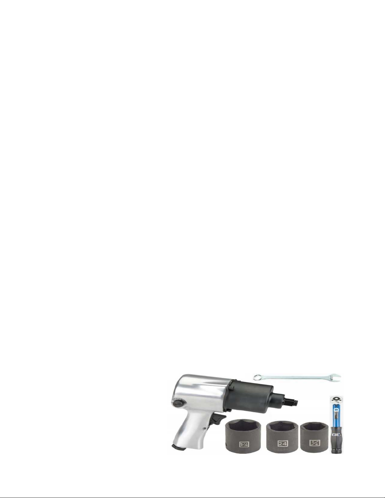
INSTALLATION TOOLS REQUIRED:
Electric or Pneumatic Impact,
Torque wrench, 24MM socket,
1 1/8” Socket & wrench,
15/16 socket & wrench, (only used on 5000 070)
¾ Socket & wrench,
7/16 socket & wrench
7
5000-070 ASSEMBLY INSTRUCTIONS
NOTE: SUPPORT THE FRONT OF THE ROW UNIT BEFORE LOOSENING ANY MOUNTING HARDWARE.
Step 1: Remove the mounting hardware for each gear box where the Yetter torsion pivot assembly will be
mounted (see torsion pivot locations on pages 10 – 12 that match your devastator kit). Install the 5000-284
Calmer Adaptor Bracket on the bottom side of the frame sliding the threaded rod through each hole of the
straps on the front of the frame and hand thread the 2502-397 5/8 – 11 X 5 ½ bolts with original lock washer
into the gear box. Slide the holes in the upright tab on the 5000-285 over the threaded rod of the 5000-284 &
hand tighten new lock washers & hex nuts.
Step 2: Place the 5000-167 torsion pivot assembly on the 5000-285 adaptor aligning all 4 holes. Thread by
hand the 2502-810 M16 X 2 X 30 bolts on the front set of holes. Place the spacer between the 5000-284
calmer adaptor bracket & the 5000-285 adaptor. Thread by hand the 2502-809 M16 X 2 65 bolts. Tighten the
hardware from steps 1 & 2 to torque spec in the following order: A – 1st, B – 2nd, C – 3rd, D – 4th.
Step 3: Refer to page 14 for instructions on installing the 5000-292 torsion arm.
8
5000-071 ASSEMBLY INSTRUCTIONS
NOTE: SUPPORT THE FRONT OF THE ROW UNIT BEFORE LOOSENING ANY MOUNTING HARDWARE.
Step 1: Remove the mounting hardware & strap for each gear box where the Yetter torsion pivot assembly will
be mounted (see torsion pivot locations on pages 10 – 12 that match your devastator kit). Install the 5000-452
Lexion adaptor bracket on the bottom side of the frame using 4) 2502-813 M16 X 2 X 70 8.8 bolts, the original
flat washers & spacer bushing. Thread bolts by hand, then tighten to torque spec. (4th bolt not shown in photo)
Step 2: Place the 5000-167 torsion pivot assembly on the 5000-285 adaptor aligning all 4 holes. Thread the
2502-810 M16 X 2 X 30 bolts by hand, and then tighten to torque spec.
Step 3: Refer to page 14 for instructions on installing the 5000-292 torsion arm.
9
5000-072 ASSEMBLY INSTRUCTIONS
NOTE: SUPPORT THE FRONT OF THE ROW UNIT BEFORE LOOSENING ANY MOUNTING HARDWARE.
Step 1:
(see torsion pivot locations on pages 10 – 12 that match your devastator kit). Place the 2) 5000-454 Spacers (longer,
used on non-Horizon Geringhoff corn heads) OR 2) 5000-472 Spacers (shorter, used on Horizon Geringhoff corn heads) in the
5000-453 Geringhoff Adaptor Plate. Put the spacers against the bottom side of the corn head frame. (this is to space the
adaptor plate away from the weldments & gear box mounting straps) Insert 1) 2502-815 M16 X 140MM through the front side
of the adaptor plate on the end that the pivot assembly is not attached to. Insert 1) 2502-814 M16 X 160MM through the back
side of the adaptor plate on the end that the pivot assembly is not attached to. Align these 2 bolts with threaded holes on the
gear box & thread by hand.
NOTE: EACH 5000-167 TORSION PIVOT ASSEMBLY THAT IS RECEIVED IN THE 5000-040A – 5000-
047A CAN BE DISCARDED
Step 2:
Place the 5000-174 torsion pivot assembly on the 5000-285 adaptor aligning 2 slotted holes with the tapped holes
on the adaptor bracket & 2 slotted holes that align with the threaded holes on the gear box. Thread the 2) 2502-810 M16 X 2
X 30 bolts by hand into the tapped holes on the adaptor bracket. Thread 1) 2502-814 M16 X 160 on the front side & 1) 2502-
817 M16 X 180 on the back side into the gear boxes by hand. Tighten all mounting hardware to torque spec at this time.
Below is a diagram showing what holes on the 5000-174 torsion pivot used on Geringhoff corn heads match with the holes in
the 5000-285 adaptor plate.
Step 3:
Refer to page 14 for instructions on installing the 5000-292 torsion arm.
10
ASSEMBLY INSTRUCTIONS
BELOW ARE RECOMMENDED LOCATIONS OF THE TORSION PIVOT ASSEMBLY, ALTERNATE
LOCATIONS MAY BE USED IF INTERFERENCE OCCURS!
5000-040 6 ROW 30”
Arrows indicate 5000-167 Torsion Pivot locations
5000-041 8 ROW 30”
Arrows indicate 5000-167 Torsion Pivot locations
5000-042 12 ROW 20”
Arrows indicate 5000-167 Torsion Pivot locations
11
ASSEMBLY INSTRUCTIONS
BELOW ARE RECOMMENDED LOCATIONS OF THE TORSION PIVOT ASSEMBLY, ALTERNATE
LOCATIONS MAY BE USED IF INTERFERENCE OCCURS!
5000-043 1290 12 ROW 20”
Arrows indicate 5000-167 Torsion Pivot locations
5000-044 12 ROW 30”
Arrows indicate 5000-167 Torsion Pivot locations
*On Rows 3 and 10, 1 set of M16 Bolts will thread into the gear box*
5000-045 18 ROW 20”
Arrows indicate 5000-167 Torsion Pivot locations
12
ASSEMBLY INSTRUCTIONS
BELOW ARE RECOMMENDED LOCATIONS OF THE TORSION PIVOT ASSEMBLY, ALTERNATE
LOCATIONS MAY BE USED IF INTERFERENCE OCCURS!
5000-046 12 ROW 22”
Arrows indicate 5000-167 Torsion Pivot locations
5000-047 18 ROW 22”
Arrows indicate 5000-167 Torsion Pivot locations
13
ASSEMBLY INSTRUCTIONS
Step 1: Attach the 5000-167 torsion mount bracket to the frame using 4) M16 X 110 flange head bolts & 2)
5000-420 clamp straps. Thread the bolts into the clamp straps by hand & tighten to torque specifications.
Note: Torque the M16 bolts @ 236 ft. /lbs.
Alternative Step 1: (20”-22” row spacing) Remove (1) toolbar strap from the gear box, then attach the
5000-158 torsion mount brackets to the frame and gear box using the 2) M16 X 120 flange head bolts and
(1) 5000-420 clamp & 2) M16 X 110 flange head bolts. Some situations may require 1 side of the gear box to
install a mounting bracket. Mounting locations may vary. The photo below on the left illustrates the gear box
bolt & clamp that need removed. The photo below on the right illustrates: Arrow A – Using 1 side of the gear
box to mount the 5000-158 torsion mount bracket using 2) M16 X 120 flange head bolts. Arrow B – Using 1)
5000-420 clamp & 2) M16X 110 flange head bolts.
Note: Torque the M16 bolts @ 236 ft./lbs.
14
ASSEMBLY INSTRUCTIONS
Step 2: Install the 5000-292 Torsion Arm onto the Torsion Pivot Assembly & secure with the ¾”
x 8” bolts & ¾” lock nuts. Refer to the diagrams on the pages 10 – 12 to determine which side of
the Torsion Pivot Assembly to install the 5000-292 Torsion Arm.
Step 3: Attach the roller mount to the pivot arms using the ½” x 2-1/2” x 3-1/2” U-bolts & lock nuts. See
the diagrams on pages 10 – 12 to determine the orientation of the roller & roller mount tube locations.
NOTE:
The bearing support tab on the roller mount tube should be on the backside of the bearing mount plate.
15
ASSEMBLY INSTRUCTIONS
Step 4: Install the Devastator roller, spacer/bushing and bearings to the roller tube
using the ½” x 2-1/2” carriage bolts. A 3R30 roller is pictured in the diagram below.
IMPORTANT: The spacer must be installed between the roller and the bearing.
The notches of the bearing housing must face the mounting plate. The
extended race on the bearing will face away from the roller.
NOTE: AFTER FASTENING THE MOUNTING
HARD ARE FOR THE BEARINGS, SPIN
EACH ROLLER BY HAND TO MAKE SURE
EACH ROLLER SPINS FREELY.
16
ASSEMBLY INSTRUCTIONS
Step 5:
Slide the roller mount tubes to align the row center with the traction bars. Fully tighten
hardware. In some circumstances, the traction bar may have to be off-center of the row some.
Step 6: (If Applicable) On chopping corn heads, trim 3 inches off the bottom of
the back curtain to keep the roller from contacting the curtain.
NOTE: Make sure the chopping blades are sharp enough to size the residue into
smaller pieces for better flow between the back curtain & roller mount tube.
17
LOCK UP
To “lock up” the Devastator rollers, lower the head down & install a rod through the hole in the mount bracket in front of the
pivot arms. A 5000-430 Lock Pin can be ordered separately to lock up the devastator rollers. 6 row heads require 1 lock pin,
8/12 row heads require 2, 18 row heads require 3.
OPERATION
CORN HEAD ANGLE NEEDS TO BE ADJUSTED BETWEEN
23 – 25° FOR OPTIMUM DEVASTATATOR PERFORMANCE.
USE THE 5000-455 TO CHECK CORN HEAD ANGLE:
- Put the combine on a level surface. Lower the
Corn head to your normal working head height.
- Place the magnetic protractor on the stripper
plate to get the angle. Adjust the feeder house
as needed, fore or aft, to achieve 23 – 25 degrees.
STORAGE/TRANSPORT
- Head cart may need adjusted to fit the head with devastator correctly. E.g., raising the saddles & top rail on the head cart.
- When disconnecting from the head, leaving pressure on the torsion pivot of the devastator will not damage the devastator.
BEARING
REPLACEMENT
Put the bearing housing in a vice, use a pry bar to turn the bearing in the housing parallel with the slots, remove the old
bearing, apply anti-seize lubricant to the interior of the bearing housing, insert the new bearing in the slots, & use a pry bar to
move back to position. Wobble the bearing around to help work the lubricant into the outer race of the bearing.
18
5000-040A PART IDENTIFICATIONS
JD 606C/706C 6R30 ALL MODELS
ITEM
PART #
DESCRIPTION
QUANTITY
1 2502-430 ¾ - 10 X 8 HHCS GR 8 ZP 4
2 2502-805 M16 X 2 X 120 HEX FLANGE BOLT, THREADLOCK, ZP (USED ONLY IN GEAR BOXES) 16
2502-806 M16 X 2 X 110 HEX FLANGE BOLT, THREADLOCK, ZP ( USED ONLY IN 4” CLAMP STRAPS) 16
3 2505-343 ½ - 13 X 2 ½ CARRIAGE BOLT, GR 5, ZP 12
4 2520-357 1/2-13 LOCK HEX NUT, GR A, ZP 28
5 2520-604 ¾ - 10 HEX TOP LOCK NUT 4
6 2570-568 ½ X 2 ½ X 3 ½ U-BOLT 8
7 5000-167 TORSION PIVOT ASSEMBLY 4
8 5000-272 3R30 ROLLER W.A. 2
9 5000-275 4R20/3R30 ROLLER MOUNT W.A. 2
10 5000-292 TORSION ARM W.A. 4
11 5000-355 BEARING ASSEMBLY 4
2550-059 DEVASTATOR BEARING (NO CAST HOUSING) 4
12 5000-420 4” CLAMP STRAP, TAPPED 8
13 5000-421 ROLLER SPACER BUSHING 4
14 5000-468 SPACER 4
15 5000-469 SECURITY CAP 8
19
5000-041A PART IDENTIFICATIONS
JD 608C/708C 8R30 ALL MODELS
ITEM
PART #
DESCRIPTION
QUANTITY
1 2502-430 ¾ - 10 X 8 HHCS GR 8 ZP 6
2 2502-805 M16 X 2 X 120 HEX FLANGE BOLT, THREADLOCK, ZP (USED ONLY IN GEAR BOXES) 24
2502-806 M16 X 2 X 110 HEX FLANGE BOLT, THREADLOCK, ZP ( USED ONLY IN 4” CLAMP STRAPS) 24
3 2505-343 ½ - 13 X 2 ½ CARRIAGE BOLT, GR 5, ZP 18
4 2520-357 1/2-13 LOCK HEX NUT, GR A, ZP 42
5 2520-604 ¾ - 10 HEX TOP LOCK NUT 6
6 2570-568 ½ X 2 ½ X 3 ½ U-BOLT 12
7 5000-167 TORSION PIVOT ASSEMBLY 6
8 5000-268 2R30 ROLLER W.A. 1
9 5000-269 2R30 ROLLER MOUNT W.A. 1
10 5000-272 3R30 ROLLER W.A. 2
11 5000-275 4R20/3R30 ROLLER MOUNT W.A. 2
12 5000-292 TORSION ARM W.A. 4
13 5000-355 BEARING ASSEMBLY 6
2550-059 DEVASTATOR BEARING (NO CAST HOUSING) 6
14 5000-420 4” CLAMP STRAP, TAPPED 12
15 5000-421 ROLLER SPACER BUSHING 6
16 5000-468 SPACER 6
17 5000-469 SECURITY CAP 12
20
5000-042A & 5000-043A PART IDENTIFICATION
JD 612C & 712C 12R20 ALL MODELS / 1290 12R20
ITEM
PART #
DESCRIPTION
QUANTITY
1 2502-430 ¾ - 10 X 8 HHCS GR 8 ZP 6
2 2502-805 M16 X 2 X 120 HEX FLANGE BOLT, THREADLOCK, ZP (USED ONLY IN GEAR BOXES) 24
2502-806 M16 X 2 X 110 HEX FLANGE BOLT, THREADLOCK, ZP ( USED ONLY IN 4” CLAMP STRAPS) 24
3 2505-343 ½ - 13 X 2 ½ CARRIAGE BOLT, GR 5, ZP 18
4 2520-357 1/2-13 LOCK HEX NUT, GR A, ZP 42
5 2520-604 ¾ - 10 HEX TOP LOCK NUT 6
6 2570-568 ½ X 2 ½ X 3 ½ U-BOLT 8
7 5000-167 TORSION PIVOT ASSEMBLY 6
8 5000-267 4R20 ROLLER W.A. 3
9 5000-275 4R20/3R30 ROLLER MOUNT W.A. 3
10 5000-292 TORSION ARM W.A. 6
11 5000-355 BEARING ASSEMBLY 6
2550-059 DEVASTATOR BEARING (NO CAST HOUSING) 6
12 5000-420 4” CLAMP STRAP, TAPPED 12
13 5000-421 ROLLER SPACER BUSHING 6
14 5000-468 SPACER 6
15 5000-469 SECURITY CAP 12

This manual suits for next models

11

Other Yetter Farm Equipment manuals

Yetter 2999 Instruction Manual

Yetter

Yetter 2999 Instruction Manual

Yetter 5000-025A User manual

Yetter

Yetter 5000-025A User manual

Yetter 5000-025C User manual

Yetter

Yetter 5000-025C User manual

Yetter MAXIMIZER User manual

Yetter

Yetter MAXIMIZER User manual

Yetter 5000 SERIES User manual

Yetter

Yetter 5000 SERIES User manual

Yetter SCREW ADJUST User manual

Yetter

Yetter SCREW ADJUST User manual

Yetter 2968-020B User manual

Yetter

Yetter 2968-020B User manual

Yetter Systems One Seed Jet II User manual

Yetter

Yetter Systems One Seed Jet II User manual

Yetter 5000-080 User manual

Yetter

Yetter 5000-080 User manual

Yetter TITAN Series User manual

Yetter

Yetter TITAN Series User manual

Yetter 5000 SERIES User manual

Yetter

Yetter 5000 SERIES User manual

Yetter 2920-012 User manual

Yetter

Yetter 2920-012 User manual

Yetter 2968-050 User manual

Yetter

Yetter 2968-050 User manual

Yetter TITAN Series User manual

Yetter

Yetter TITAN Series User manual

Yetter 2995 XFC User manual

Yetter

Yetter 2995 XFC User manual

Yetter 6200-022 User manual

Yetter

Yetter 6200-022 User manual

Yetter 5500 Series User manual

Yetter

Yetter 5500 Series User manual

Yetter 2968-026 User manual

Yetter

Yetter 2968-026 User manual

Yetter 2967-035A User manual

Yetter

Yetter 2967-035A User manual

Yetter 5000 SERIES User manual

Yetter

Yetter 5000 SERIES User manual

Yetter 5000 SERIES User manual

Yetter

Yetter 5000 SERIES User manual

Yetter 2967-006A User manual

Yetter

Yetter 2967-006A User manual

Yetter 5000-023A User manual

Yetter

Yetter 5000-023A User manual

Yetter 2965 Series User manual

Yetter

Yetter 2965 Series User manual

Popular Farm Equipment manuals by other brands

Harvest TEC 747C installation manual

Harvest TEC

Harvest TEC 747C installation manual

Schaffert G2 Mounting instructions

Schaffert

Schaffert G2 Mounting instructions

In The Ditch X Series Tech tips

In The Ditch

In The Ditch X Series Tech tips

Arrowquip PORTABLE Q-CATCH 74 Series product manual

Arrowquip

Arrowquip PORTABLE Q-CATCH 74 Series product manual

SIP STAR 300 Instruction for work

SIP

SIP STAR 300 Instruction for work

GSi Cumberland PNEG-1333 Installation and owner's manual

GSi

GSi Cumberland PNEG-1333 Installation and owner's manual

CrustBuster 3200 owner's manual

CrustBuster

CrustBuster 3200 owner's manual

SaMASZ UNO 600 Operator's manual

SaMASZ

SaMASZ UNO 600 Operator's manual

LEMKEN Solitair DT/400 operating instructions

LEMKEN

LEMKEN Solitair DT/400 operating instructions

J&M 1012 Operator's manual

J&M

J&M 1012 Operator's manual

Jula 729-028 operating instructions

Jula

Jula 729-028 operating instructions

KUHN HR3004D Operator's manual

KUHN

KUHN HR3004D Operator's manual

TATU LTA 3000 instruction manual

TATU

TATU LTA 3000 instruction manual

LELY SPLENDIMO 280 FC Operator's manual

LELY

LELY SPLENDIMO 280 FC Operator's manual

aivituvin AIR42 instruction manual

aivituvin

aivituvin AIR42 instruction manual

Pottinger NOVACAT V 10000 Original operating instructions

Pottinger

Pottinger NOVACAT V 10000 Original operating instructions

Hagie NTB 16-Row Operator's manual

Hagie

Hagie NTB 16-Row Operator's manual

KIFCO Water-Reel T/E210L Assembly instructions

KIFCO

KIFCO Water-Reel T/E210L Assembly instructions

manuals.online logo
manuals.online logoBrands
  • About & Mission
  • Contact us
  • Privacy Policy
  • Terms and Conditions

Copyright 2025 Manuals.Online. All Rights Reserved.