MachMotion 2000 Series User manual

Limits of increasing the performance of Industrial Ethernet protocols - Scientific Figure on ResearchGate. Available
from: https://www.researchgate.net/figure/EtherCAT-with-100-Mbps_fig4_4304922 [accessed 21 Jan, 2022]
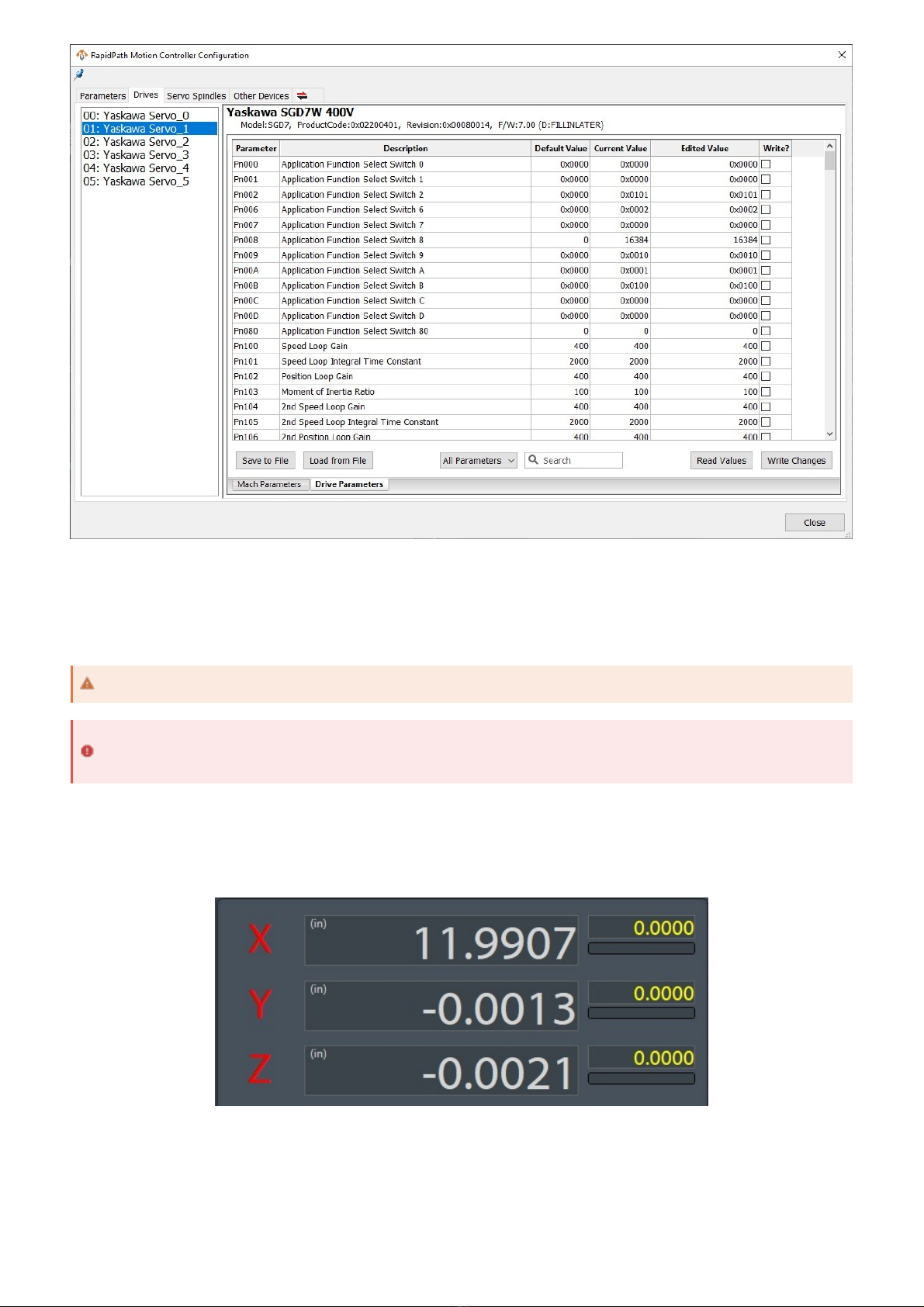
RapidPath is MachMotion's EtherCAT motion controller solution. It has integrations for a range of Yaskawa EtherCAT
servo drives, VFDs, the Titanio EverCNC stepper drive, and a subset of the Beckhoff I/O devices. It can be licensed for
up to 64 motors. The control uses a Windows interface to a real time operating system where the EtherCAT master
resides. The operating system is called Intime and the interface is called RapidSetup.
An EtherCAT network is comprised of a communication master and a series of network nodes. Each millisecond, a
packet of information (known as a frame) is sent from the master to the network and a responding frame is received
back. The frame from the master includes information for each node, such as commanded axis position and outputs.
The frame the master receives back includes feedback position and input status, among many other things.
An EtherCAT network is a sequence of devices called nodes. A node is added to the network by plugging an EtherCAT
cable from the out port of one node to the in port of the next node. The in port of the first node is attached to the
EtherCAT port on the back of the control. The out port of the last node will be empty and unconnected. This will create
a chain of devices in order.
I/O couplers will have multiple node items on the network for each coupler. Only the couplers have in and out ports,
but each I/O slice is a distinct node on the network. Some I/O slices that are all 0V connections are not part of the
network. Other example of potential network nodes include servo drives and VFDs.
When there are changes to the network topology due to nodes being added or removed, the communication on the
network will be shut down and the system will have to regenerate. If the machine is running during this time, all
systems will disable. The machine is unable to be enabled while the network is not operational.
If the network has had nodes added to it, the regeneration process will need no interaction from the operator. If the
network has had nodes removed from it, the control will ask if the user wants to override the saved topology and use
the new network. This may result in settings or I/O mappings being lost, as some devices are no longer on the network.
Note that the network does not distinguish unique order of nodes on the network; if you swap the order of two servo
2000 Series RapidPath Operating
Manual
Introduction
EtherCAT Network Basics
Communication
Building a Network
Regenerating a Network

drives, control settings will not move with the original devices and may create unexpected motion.
An axis is added to the network by plugging an EtherCAT cable from the out port of one node to the in port of the new
servo node. Adding or removing items from the network will break the communication stream and cause the network
to regenerate. While the network is regenerating, the machine cannot be enabled and config cannot be accessed.
The motors are labeled starting at zero. The first motor is the first motor on the network and sequentially added from
there. All motors must be enabled before they can be assigned to an axis. See the Servo Spindle section for using a
servo as a spindle.
1. On the menu bar, click Configure -> Control, then select the Motors tab.
2. Enable all the motors that are to be controlled as axes by checking the respective boxes in the right pane.
3. Press Apply to save any changes.
Configuration
Overview
All configuration must be done while the machine is disabled.
Axis Configuration
Connecting Axes
Enabling Axes
This may already be setup on your system.

After motors are enabled, they can be assigned to axes. An axis must have one master motor and can support up to
five slave motors.
1. On the menu bar, click Configure -> Control, then select the Axis Mapping tab.
2. Enable the needed axes by checking the checkbox in the first column next to the axis name.
3. Associate the enabled motors to their applicable axis.
4. Press Apply to save any changes.

By default, the control will assume that moving an axis in the positive direction is done by turning it's motors in the
positive direction. This can be changed to match the physical mechanics of the machine.
1. On the menu bar, click Configure -> Control, then select the Motors tab.
2. Select the motor that you need to change by selecting it from the list on the right side. Be careful not to
disable it by clicking the checkbox.
3. Check the Reverse checkbox at the bottom of the screen to change the direction of motor travel.
4. Press Apply to save any changes.
The maximum velocity and acceleration values are set on a per-motor basis. If an axis has multiple motors, it will use
the slowest values of it's motors. All values are set in machine units. The graph of the motion profile will update as you
change these values.
1. On the menu bar, click Configure -> Control, then select the Motors tab.
2. Select the motor that you need to change by selecting it from the list on the right side. Be careful not to
disable it by clicking the checkbox.
3. Change the Velocity and Acceleration values to fit your motor capabilities and machine comfort.
4. Press Apply to save any changes.
For the axes to move the correct distance, the counts per unit must be calibrated correctly. For best results,
automatically calculate the units from machine data. However, unit calibration can be quite good with manual
calibration, especially if done over greater distances.
Automatic unit calibration requires detailed knowledge of your machine mechanics.
1. On the menu bar, click Configure -> Plugins -> Machine Calibration , then select Automatic
Calibration.
2. Fill out the known information about the axis. All enabled fields are required.
3. Select the axis this drive is attached to.
4. Press the Calculate button.
5. Press the Accept button to save the changes to the motors.
6. Repeat at step 2 for all axes.
7. Click OK and restart the software to save the changes.
The machine can now run motion, but units and direction have not yet been calibrated. Use extreme caution
when moving the machine.
Motor Direction, Velocity, and Acceleration
Motor Direction
If you are slaving motors for a gantry axis, they very often must run in opposite directions in order to not twist
the machine.
Maximum Velocity and Acceleration
Calibrating Units
Automatic Unit Calibration

Manual unit calibration does not require any knowledge of the machine mechanics, but does require an accurate way
to measure distance moved by an axis.
1. On the menu bar, click Configure -> Plugins -> Machine Calibration , then select Manual Calibration.
2. Select the axis to calibrate.
3. Select Commanded Distance.
4. Enter the distance to move the axis and the feedrate to move at.
5. Press the Enable button to enable the machine for motion.
6. Press the Move button to start motion on the selected axis.
7. Enter the actual distance moved and click Submit.
8. Click Accept to write the units to the motors.
9. Repeat on all axes until satisfied with accuracy of the machine.
10. Click OK and restart the software to save the changes.
Manual Unit Calibration

The units for individual motors can be manually adjusted in the control configuration on the motors tab. This is not
recommended for normal calibration. If the units are manually adjusted here, also adjust them to match on the
Auxiliary Positions tab. You do not need to enable anything on this page, but the counts per unit must be kept in sync.
The RapidPath motion controller supports backlash compensation. Backlash compensation cannot fix all errors in the
mechanics. It is better to fix the mechanics than hope that backlash compensation can make up for it.
1. Calculate the backlash value.
1. Move the axis to be measured to the center of the machine.
2. Open MDI and type gcode to move the axis in the positive direction.
3. Mount a dial indicator to the axis and zero it.
4. Using MDI, move the axis a specific distance in the positive direction.
5. Move the axis the same distance in the negative direction.
6. The backlash value is the amount that the dial indicator is off from zero.
2. On the menu bar, click Configure -> Control, then select the Motors tab.
3. Select the motor that you need to change by selecting it from the list on the left side. Be careful not to disable
it by clicking the checkbox.
4. Enter the Backlash value measured in machine units.
5. Press Apply to save any changes and OK to close the configuration window.
6. On the menu bar, click Configure -> Plugins -> RapidPath, then select the Drives tab.
7. Select the motor that you need to change by selecting it from the list on the left side.
8. Enter the desired Backlash Rate. The rate is a percentage of the motors maximum velocity and is how
quickly the backlash will be compensated for when changing direction. A common value is 20%.
9. Press Close to close the configuration window.
Manual Unit Adjustment
Backlash

Drive parameters are directly editable from the control software without any additional cables.
1. On the menu bar, click Configure -> Plugins -> RapidPath, then select the Drives tab.
2. Select the motor that you need to change parameters on by selecting it from the list on the left side.
3. Select the Drive Parameters tab.
On this page, you can view and edit all parameters on the drive. Edited parameters will be highlighted in green. The
parameters can be saved to a file or loaded from a previous save.
At this point, axes should have correct motion with accurate units and reasonable speeds and accelerations.
The machine has not been homed and limits have not been set up. Use caution while moving the machine.
Drive Parameters
This file format is not compatible with parameter files from other software.

RapidPath supports a variety of homing methods. The exact methods available will depend on the capabilities of your
drives.
The home status of any axis can be seen on the main page. If an axis is not homed, the letter by it's position DRO will
flash red and yellow. If an axis is homed, the letter will turn black. All motors on an axis must succeed at homing for an
axis to report homed.
Axes can be homed individually or all together in their defined order. Each axis will follow the same general sequence
for homing.
1. Each motor on the axis will complete it's homing action as configured. Each method of homing requires
different configuration needs.
2. The axis will wait for all motors to be done.
Homing
Units must be set up and accurate before doing any homing operations.
If limit switches are to be used on your machine, it is recommended to set those up before homing. See Limit
Switches.
Home Status
General Homing Sequence

3. Each motor on the axis will move to it's end position.
4. The axis will wait for all motors to be done and then report homed.
All axes must know which direction to travel in order to find their home position, the speed at which to travel at, the
offset from the marker to call their home position, and the order in which all axes home. Axes can also be homed
individually if needed.
1. On the menu bar, click Configure -> Control, then select the Homing / SoftLimits tab.
2. For each enabled axis, enter the following information:
Home Dir: the direction of travel the axis must move to find it's home condition (eg. home switch)
Home Order: the order in which axes should home when all axes are homing together. This is used for
managing potential interferences, particularly with Z axes.
Home Offset: the distance between the home condition (eg. home switch) and the desired home
position. This allows the home switch to be outside normal travel of the axis and the home position to be
inside normal travel of the axis. The axis does not move this distance without a separate parameter
being set elsewhere.
Home Speed %: the percentage of max velocity for the axis to travel towards it's home condition. The
axis must be moving sufficiently slowly to not overtravel past it's home switch.
Home In Place: Unselect for all axes. This is not a supported option on RapidPath.
3. Press Apply to save any changes and OK to close the configuration window.
The motor specifics of the homing operation are configured in the RapidPath configuration window. When choosing
homing options for slaved or gantry motors, use caution when configuring the homing sequence that the motors do not
pull the axis out of shape.
The homing methods below detail how a motor will find it's home condition. The homing method is configured in the
RapidPath configuration window.
1. On the menu bar, click Configure -> Plugins -> RapidPath, then select the Drives tab.
General Homing Setup
Regarding Home Speed %, the axis must be sufficiently slow to not overtravel past it's home switch.
The Home In Place option is not supported on RapidPath.
Selecting Homing Method
Homing Method Options

2. Select the motor that you need to change by selecting it from the list on the left side.
3. Choose the desired homing method from the drop down labeled Homing Method.
Home to current position does not move the motor in any direction. It will call it's current location the home position.
This method is most often used with absolute encoders as repeatability can be difficult. Often the machine will be
scribed to show where the home position is in case of needing to home again (eg. encoder backup battery error).
Home to index pulse will create up to one motor revolution of motion. The mechanics of your machine will dictate how
much physical motion this will create. This method is most often used with absolute encoders as repeatability can be
difficult. Often the machine will be scribed to show where the home position is in case of needing to home again (eg.
encoder backup battery error).
Home to switch will move the axis in at the homing speed in the homing direction until it finds the home switch, then
moves in the opposite direction until just off the home switch. The home switch can also be a limit switch. The home
input must be mapped in the control configuration window to the appropriate input signal, which will be named Motor
# Home, where # is the motor number. See Home Switches in the I/O Configuration section for more information
about assigning the I/O point to the home signal. For master and slave motors, the signals can be mapped to the same
I/O point or different I/O points.
Home to switch then index will function the same as Home to Switch, but after finding the home switch the motor will
move in the opposite direction to find the index pulse. The location of the index pulse will be the home location. This
method is most reliable for repeatedly finding the same home location each time.
The following parameters can modify the homing sequence to change where the home position is relative to the
triggered home position (i.e. switch or index pulse) or can create motion on the axis to change where the axis moves to
compared to it's home position is.
The following parameters are in the RapidPath configuration window:
1. On the menu bar, click Configure -> Plugins -> RapidPath, then select the Drives tab.
2. Select the motor that you need to change by selecting it from the list on the left side.
Available modifiers:
Home Offset: shifts the home position of the motor from the detected position, in machine units. This is most
often used for slave alignment between multiple motors.
Is Home Offset Directional?: determines if the Home Offset parameter is intelligently applied based on motor
polarity and home direction, or if the direction of the offset is already included. Selecting No will have the control
choose the direction to apply the offset.
Home Backoff Speed: an absolute speed (machine units/minute) that the motor will use to back off of it's
homing condition. Most commonly used in Home to Switch or Home to Switch, then Index Pulse.
Home End: Move to Position: enables the motor moving to an absolute position after determining it's home
position. Due to accelerations and offsets, many home routines do not end directly at the machine zero position.
Enabling this parameter will allow the machine to move to a specified machine position after homing.
Home End: Move to Position Speed: an absolute speed (machine units/minute) the motor will use when going
to the specified home end position.
Home End: Move to Position Target: the machine position the motor should move to after finding the home
trigger and applying the home offsets.
The following parameters are in the control configuration window:
1. On the menu bar, click Configure -> Control, then select the Homing/SoftLimits tab.
Available modifiers:
Home Offset: moves the home position for all motors on the axis by the specified value in machine units.
Home to Current Position
Home to Index Pulse
Home to Switch
The motor must be moving sufficiently slow to not overshoot the home input.
Home to Switch, then Index Pulse
Homing Modifiers

Absolute encoders can be enabled per motor. They must be enabled on the motion controller level and in the drive
parameters.
1. On the menu bar, click Configure -> Plugins -> RapidPath, then select the Drives tab.
2. Select the motor that you need to change by selecting it from the list on the left side.
3. Set the Encoder Type parameter appropriately.
4. Select the Drive Parameters tab and wait for the current parameters to be read from the drive.
5. Set the drive parameter appropriately for the encoder type.
6. Click Write Changes to send the parameters to the drive.
The documentation for the Yaskawa EtherCAT Sigma7 drives state the following about setting the encoder type in the
drive parameters:
If the motors are already homed and need to be homed again, resetting the absolute encoders will allow you to home
again. See Resetting Absolute Encoders.
Absolute Encoders

Homing should now be completely set up. Home each axis individually to verify the configuration. Press the Home
All button again to make sure everything works correctly.
After the machine is homed, soft limits can be set up. These limits affect the motion planning so that the axes will not
go outside of the designated area.
The soft limits of the machine are denoted on the toolpath by dashed lines. When a gcode file is loaded, if any part of
the toolpath renders outside of the soft limits, check your file or fixture offsets.
First Homing
If homing is incorrectly configured, the machine could crash. Be prepared to trigger Emergency Stop until
configuration is verified.
If limit switches are to be used on your machine, it is recommended to set those up before homing. See Limit
Switches.
Soft Limits
While the home switch may be outside of soft limits, machine zero must be inside soft limits.
Soft limits must be contained to stay within any physical limit switches in order to be effective.

1. Home the machine.
2. Change the position DROs to Machine Coordinates. This is indicated by them being orange. Part
coordinates (defined by G54) are shown in gray.
3. For each axis, jog the machine to one extent of travel and record the machine coordinate at that point.
4. For each axis, jog the machine to the other extent of travel and record the machine coordinate at that point.
5. On the menu bar, click Configure -> Control, then select the Homing/SoftLimits tab.
6. Enable soft limits on the desired axes by checking the Soft Enable checkmark on their row.
7. Enter the corresponding recorded positions for each axis into Soft Min and Soft Max.
Soft Min must be less than Soft Max.
Zero (0.0000) must be between Soft Min and Soft Max.
8. Press Apply to save any changes and OK to close the configuration window.
9. Verify soft limits are active.
1. Go to Service -> Maintenance on the main page.
2. The Soft Limits button should be green to indicate soft limits are active.
10. Verify the soft limits by jogging the axes to the extents of the machine in all directions.
During the normal course of operation, soft limits will be active when the machine completes homing.

All I/O points on the system are identified by their device and name. The device will indicate the physical component
the I/O is a part of and the name will indicate which terminal on the device corresponds to the I/O point.
RapidPath has integrations to Beckhoff I/O couplers and slices. The couplers are the devices and the slice order and
terminal form the name of the I/O point.
The devices are identified by their part name and their order on the network. The most common coupler used is the
EK1100, so the first coupler on the network is EK1100.1. The second coupler is EK1100.2. Most systems will only have
one coupler, but larger systems with multiple banks of I/O will have multiple couplers.
Each terminal attached to the coupler is identified by it's slice type, slice number, and terminal number. Slice types are
two letter designations for analog or digital and input or output. An analog output slice will be a AO type and a digital
input slice will be a DI type. Slices are counted starting at one from the first slice, skipping all distribution slices (0V
and 24V slices). All slices should be marked at the top with their type and slice number. The individual terminal
numbers are counted from one to eight (or four), in a left to right, top to bottom pattern. The top left terminal will be
one, the top right terminal will be two. All terminals will be marked on the slice. So the full path to an example I/O point
would be EK1100.1/DO.03.04, which translates to the first coupler, the third slice (skipping over distribution slices),
and the fourth terminal on the slice.
There are 64 general purpose inputs available for use. Inputs should also be mapped to the limit switch inputs and the
home switch inputs if those are part of your machine.
1. On the menu bar, click Configure -> Control, then select the Input Signals tab.
2. Scroll to the signal you want to map an I/O point to.
3. Enable the signal by checking the box for Mapping Enabled.
4. Select the Device that owns the I/O point from the drop down.
5. Select the Input Name from the drop down.
6. Check the Active Low box if the input is wired active low. This means the signal will be active when the I/O
point is low. This is commonly used as a safety mechanism for home switches and limit switches.
7. For the 64 general purpose inputs, give the signal a User Description that describes what the signal
represents. This description will be used throughout the control. If no description is given, the signal name will
be used.
8. Press Apply to save any changes and OK to close the configuration window.
At this point, the machine is safe to move while soft limits are active.
I/O Configuration
Beckhoff I/O Naming Convention
The terminal labeling on the front of the coupler is incorrect.
Assigning I/O to Input Signals

Each motor has a limit switch signal for positive and negative overtravel. These signals must be enabled and mapped
to the appropriate I/O point to work. The signals are called Motor # ++ and Motor # --, where # is the motor number.
The I/O point that is mapped here needs to be the one that the limit switch for that motor is wired into. The same input
can be used for both ends of an axis, if the machine is wired in that way. When a limit switch is triggered, it will disable
the machine.
Limit Switches
If these signals are not mapped correctly, the machine will not stop motion or disable when a limit switch is
triggered.

Each motor has a home signal for use during homing. If a motor is not using the Home to Switch method, then it's
signal does not need to be configured. The home signal for a motor is called Motor # Home, where # is the motor
number. The I/O point that is mapped here needs to be the one that the home switch for that motor is wired into.
Multiple motors can share a home switch input, if the machine is wired in that way. A limit switch can also function as
a home switch.
Home Switches
If these signals are not mapped correctly, the machine will not stop when the home switch is triggered during
homing.
If a limit switch is used as a home switch, then it will not disable the machine while homing.

There are 64 general purpose outputs available for use.
1. On the menu bar, click Configure -> Control, then select the Output Signals tab.
2. Scroll to the signal you want to map an I/O point to.
3. Enable the signal by checking the box for Mapping Enabled.
4. Select the Device that owns the I/O point from the drop down.
5. Select the Output Name from the drop down.
6. Check the Active Low box if the output is wired active low. This means the signal will be active when the I/O
point is low.
7. Give the signal a User Description that describes what the signal represents. This description will be used
throughout the control. If no description is given, the signal name will be used.
8. Press Apply to save any changes and OK to close the configuration window.
Assigning I/O to Output Signals

Many machines utilize mist and coolant outputs on the machine. The output signals for them are called Coolant On
and Mist On. They can be controlled in gcode files with M07 (mist) and M08 (coolant), with M09 turning both outputs
off.
The process for assigning analog I/O to analog signals is identical for inputs and outputs. The instructions below are for
the 16 bit Beckhoff analog I/O cards. For other cards or non-standard use, see Calculating Analog Scaling.
1. On the menu bar, click Configure -> Control, then select the Analog Inputs tab.
For analog outputs, select the Analog Outputs tab instead.
2. Select the Device that owns the I/O point from the drop down.
3. Select the Analog Name from the drop down.
4. Set the Numerator to 100.
5. Set the Denominator to 65535.
6. Set the Offset to 0.
7. Give the signal a User Description that describes what the signal represents. This description will be used
throughout the control. If no description is given, the signal name will be used.
8. Press Apply to save any changes and OK to close the configuration window.
Mist and Coolant Control
Assigning I/O to Analog Signals

The Numerator, Denominator, and Offset values associated with an analog signal all deal scaling the user values of
the I/O point to the physical values of the I/O point. Analog values are represented by a certain number of bits, which is
often unwieldy for user use. For instance, a 16 bit analog value is represented by the range 0 to 65535, however an
operator probably prefers to think of it in terms of volts or percentage.
The Numerator is calculated as the range of values that the user wants to use. If they have a +/- 10V analog signal
that they want to think of in percentages, then the range is -100 to 100, and the which in turn makes the numerator
value 200 (100 - (-100) = 200). Alternatively, if they have a 0-10V analog signal, the range would be 0 to 100, making
the numerator value 100 (100 - 0 = 200). The numerator is the maximum of the range minus the minimum of the
range.
The Denominator is the range of physical values that the signal can support. For this, you need to know the number
of bits in the signal and if the signal is +/- or only positive voltage. The maximum value for the signal range will be
2^(bits - 1), and the minimum value will either be 0 or -(2^(bits - 1). For the 16 bit 0-10V, that works out to 2^(16 - 1)
= 2^15 = 65535 at the high end and 0 at the low end. If it were +/- 10V, then the low end would be -65535. The value
for the denominator is then the high end value minus the low end value. For our examples, either (65535 - 0 = 65535)
or (65535 - (-65535) = 131070.
The Offset is calculated from the numerator and denominator values. First, we need our m value, which we will get by
dividing the numerator by the denominator. Then we will use the upper values of the numerator range and the
denominator range to get the offset value. The offset is (upper numerator - m*(upper denominator)).
Beckhoff Slice Type
Bit Width
Denominator Lower
Denominator Upper
Denominator Value
Calculating Analog Scaling
16 bit +/- 10V Analog Output
Numerator range: -100 to 100
Numerator value: 100 - (-100) = 200
Denominator upper value: 2^(16 - 1) = 65535
Denominator lower value: -1 * (2^(16 - 1)) = -65535
Denominator range: -65535 to 65535
Denominator value: 65535 - (-65535) = 131070
m value: 200 / 131070 = 0.00152
Offset: 100 - (65535 * 0.00152) = 0
Numerator: 200
Denominator: 131070
Offset: 0

Beckhoff Slice Type
Bit Width
Denominator Lower
Value
Denominator Upper
Value
Denominator Value
EL4034
16
-65535
65535
131070
EL3002
16
-65535
65535
131070
RapidPath supports up to ten probe signals. The probe signals should be mapped to the corresponding I/O point in the
control configuration. Any of the Beckhoff I/O points can be used as probe inputs. If a probe is wired into a servo drive
directly, then it must be wired into latch inputs on all drives or must also be wired into a Beckhoff I/O.
The basic Probe signal corresponds to the gcode G31. All subsequent probe signals correspond to G31.#, where # is
their probe index. For example, the Probe9 signal is gcode G31.9.
1. On the menu bar, click Configure -> Control, then select the Input Signals tab.
2. Scroll to the probe signal you want to map an I/O point to. The available probe signal names are:
Probe
Probe1
Probe2
Probe3
Probe4
Probe5
Probe6
Probe7
Probe8
Probe9
3. Enable the probe signal by checking the box for Mapping Enabled.
4. Select the Device that owns the I/O point from the drop down.
5. Select the Input Name from the drop down.
6. Check the Active Low box if the input is wired active low. This means the signal will be active when the I/O
point is low. This is commonly used as a safety mechanism for probe inputs.
7. If multiple probes are in use on the machine, give the signal a User Description that describes which probe
the signal represents. This description will be used throughout the control. If no description is given, the
signal name will be used.
8. Press Apply to save any changes and OK to close the configuration window.
9. On the menu bar, click Configure -> Plugins -> RapidPath, then select the Drives tab.
10. For each motor, select G31.# Probe Input probe source
If the probe signal is mapped to a Beckhoff I/O, select Motion Controller
If the probe is wired directly to the front of this motor, select the corresponding Probe Input #
11. Press Close to close the configuration window.
Probing
It is not recommended to wire probe inputs to the latch signals on the servo drives.
It is highly recommended to use a Beckhoff I/O for probe inputs and use the Motion Controller probe source
for all motors.
Other manuals for 2000 Series
2
This manual suits for next models
1
Table of contents
Other MachMotion Industrial PC manuals
Popular Industrial PC manuals by other brands

DFI
DFI DT122-SB installation guide

Sintrones
Sintrones ABOX-5000P user manual

Lex System
Lex System TERA 2I610DW Assembly guide

Onlogic
Onlogic Karbon 800 Series product manual

Moxa Technologies
Moxa Technologies TC-6110 Series Quick installation guide

Arbor Technology
Arbor Technology FPC-9108 Series user manual