manuals.online logo
Brands
  1. Home
  2. •
  3. Brands
  4. •
  5. MACHRUS
  6. •
  7. Greenhouse Kit
  8. •
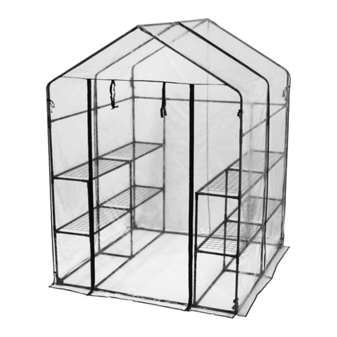
  9. MACHRUS OGAL-666A User manual

MACHRUS OGAL-666A User manual

OGAL-666A
GREENHOUSE ASSEMBLY
INSTRUCTIONS
Email:
US/Canada: [email protected]
UK: [email protected]
Check out our website:
www.Machrus.com
Machrus Cornwall, NY 12518
Phone:
US/Canada: 1-888-965-3331
UK: 020-3150-0484
Notes:
1. It takes about 2-3 hours to assemble the greenhouse by 2-3 persons.
2.The UV-protected side of the sheet is covered with opal white film and
must face towards the sun.
3.Remove approximately 2 inches of film from all sheet edges before
installing.Removing all film immediately after the construction is
completed
4.Make sure the greenhouse is located on a flat, level surface.
TO PREVENT INJURY, READ AND UNDERSTAND THE
GREENHOUSE ASSEMBLY INSTRUCTIONS BEFORE USE.
GENERAL SAFETY, WARNINGS AND PRECAUTIONS
KEEP WORK AREA CLEAN AND DRY.
Cluttered, damp or wet work areas invite injuries.
STAY ALERT. Watch what you are doing at all times. Use common
sense. Do not use the greenhouse when you are tired or distracted from
the job at hand. It is recommended to use gloves for assembling the
greenhouse.
MAINTAIN THIS PRODUCT WITH CARE.
Keep the greenhouse clean and dry for better performance:
maintenance should be performed regularly.
USE THE RIGHT PRODUCT FOR THE JOB.
Do not attempt to force a small product to do the work of a larger
industrial product. There are certain applications for which the
greenhouse was designed. It will do the job better and more safely in the
manner for which it was intended. Do not modify the greenhouse and do
not use the greenhouse for a purpose for which it was not intended.
MAINTAIN A SAFE WORKING ENVIRONMENT.
Keep the work area tidy. Make sure there is adequate surrounding
workspace. Avoid high traffic areas. Always keep the work area free of
obstructions, grease, oil, trash and other debris.
PROPER GREENHOUSE LOCATION.
Make sure the greenhouse is located on a flat, level surface.
TO PREVENT INJURY, PLEASE READ AND UNDERSTAND THE
GREENHOUSE
ASSEMBLY INSTRUCTIONS MANUAL
BEFORE
USE.
Notes:
1.
Around 2-3 hours is needed to assemble the greenhouse by 2-3
individuals.
2.
The UV-protected side of the panel sheets is covered with opal
white film and must be placed facing the sun.
3. Before installing the sheets, remove around 2 inches of film from all
the edges. Once the construction is completed, remove the the entire
film immediatel
y.
4. Ensure that the greenhouse is located on a flat and level surface.
GENERAL SAFETY, WARNINGS AND PRECAUTIONS
KEEP WORKING AREA CLEAN AND DRY.
Cluttered, damp or wet working areas invite injuries.
BE
ALERT. Always be cautious of your actions. Use your common
sense. Do not assemble the structure if you are tired or distracted.
Use gloves when assembling the greenhouse.
HANDLE THIS PRODUCT WITH CARE
Keep the greenhouse clean and dry to maintain better performance.
Also, regular maintenance must be done.
USE THE SUITABLE TOOLS FOR THE JOB
Do not use small tools in lieu of larger ones. Tools are not suitable for
every type of work.
The greenhouse is designed in order to provide
better condition and safet
y. So, do not perform any modification on
the greenhouse. Do not use it aside from its intended purpose.
MAINTAIN A SAFE WORKING ENVIRONMENT
Keep your working area clean and organized. Make sure that there is
enough space for you to work on.
Avoid crowded areas. Also, keep
source of obstruction, grease, oil or trash far from your working zone.
PROPER GREENHOUSE LOCATION
Place the greenhouse on a flat and level surface.
Notes:
1. It takes about 2-3 hours to assemble the greenhouse by 2-3 persons.
2.The UV-protected side of the sheet is covered with opal white film and
must face towards the sun.
3.Remove approximately 2 inches of film from all sheet edges before
installing.Removing all film immediately after the construction is
completed
4.Make sure the greenhouse is located on a flat, level surface.
TO PREVENT INJURY, READ AND UNDERSTAND THE
GREENHOUSE ASSEMBLY INSTRUCTIONS BEFORE USE.
GENERAL SAFETY, WARNINGS AND PRECAUTIONS
KEEP WORK AREA CLEAN AND DRY.
Cluttered, damp or wet work areas invite injuries.
STAY ALERT. Watch what you are doing at all times. Use common
sense. Do not use the greenhouse when you are tired or distracted from
the job at hand. It is recommended to use gloves for assembling the
greenhouse.
MAINTAIN THIS PRODUCT WITH CARE.
Keep the greenhouse clean and dry for better performance:
maintenance should be performed regularly.
USE THE RIGHT PRODUCT FOR THE JOB.
Do not attempt to force a small product to do the work of a larger
industrial product. There are certain applications for which the
greenhouse was designed. It will do the job better and more safely in the
manner for which it was intended. Do not modify the greenhouse and do
not use the greenhouse for a purpose for which it was not intended.
MAINTAIN A SAFE WORKING ENVIRONMENT.
Keep the work area tidy. Make sure there is adequate surrounding
workspace. Avoid high traffic areas. Always keep the work area free of
obstructions, grease, oil, trash and other debris.
PROPER GREENHOUSE LOCATION.
Make sure the greenhouse is located on a flat, level surface.
TO PREVENT INJURY, PLEASE READ AND UNDERSTAND THE
GREENHOUSE ASSEMBLY INSTRUCTIONS MANUAL BEFORE
USE.
Notes:
1. Around 2-3 hours is needed to assemble the greenhouse by 2-3
individuals.
2. The UV-protected side of the panel sheets is covered with opal
white film and must be placed facing the sun.
3. Before installing the sheets, remove around 2 inches of film from all
the edges. Once the construction is completed, remove the the entire
film immediately.
4. Ensure that the greenhouse is located on a flat and level surface.
GENERAL SAFETY, WARNINGS AND PRECAUTIONS
KEEP WORKING AREA CLEAN AND DRY.
Cluttered, damp or wet working areas invite injuries.
BE ALERT. Always be cautious of your actions. Use your common
sense. Do not assemble the structure if you are tired or distracted.
Use gloves when assembling the greenhouse.
HANDLE THIS PRODUCT WITH CARE
Keep the greenhouse clean and dry to maintain better performance.
Also, regular maintenance must be done.
USE THE SUITABLE TOOLS FOR THE JOB
Do not use small tools in lieu of larger ones. Tools are not suitable for
every type of work. The greenhouse is designed in order to provide
better condition and safety. So, do not perform any modification on
the greenhouse. Do not use it aside from its intended purpose.
MAINTAIN A SAFE WORKING ENVIRONMENT
Keep your working area clean and organized. Make sure that there is
enough space for you to work on. Avoid crowded areas. Also, keep
source of obstruction, grease, oil or trash far from your working zone.
PROPER GREENHOUSE LOCATION
Place the greenhouse on a flat and level surface.
www.machrus.com

6X6FT
79 inches x 76 inches x 75 inches
OGAL-666A
6X6FT
79 inches x 76 inches x 75 inches
OGAL-666A
www.machrus.com
Notes:
1. Remove approximately 2 inches of film from all the sheet edges prior to installation.
Upon completion, immediately remove all the remaining film.
2.
The UV-protected side of the sheet, which is covered with opal white film, must face
the sun.
Front
Rear
Notes:
1. Remove approximately 2 inches of film from all the sheet edges prior to installation.
Upon completion, immediately remove all the remaining film.
2. The UV-protected side of the sheet, which is covered with opal white film, must face
the sun.
Front
Rear
www.machrus.com
SKU #
OGRPT-F-03b
OGRPT-F-04
SKU #
OGRPT-F-20
OGRPT-F-25
OGRPT-F-26
OGRPT-F-27
OGRPT-F-28
OGRPT-F-37
SKU #
OGRPT-F-12
OGRPT-F-13
OGRPT-F-14b
OGRPT-F-15
OGRPT-F-16b
OGRPT-F-21
OGRPT-F-22b
OGRPT-F-38
OGRPT-F-39
SKU #
OGRPT-G-P1
OGRPT-G-P2
OGRPT-G-P3L
OGRPT-G-P3R
SKU #
OGRPT-F-05
OGRPT-F-06
OGRPT-F-07
OGRPT-F-08
OGRPT-F-09
OGRPT-F-23
OGRPT-F-24
OGRPT-F-10
OGRPT-F-11
OGRPT-F-B05
OGRPT-F-B06
OGRPT-F-17
OGRPT-F-18
OGRPT-F-29
OGRPT-F-30
OGRPT-F-B07
OGRPT-F-31
OGRPT-F-32
OGRPT-F-33
OGRPT-F-34
OGRPT-F-35
OGRPT-F-36
OGRPT-F-40
OGRPT-F-19
OGRPT-F-19b
SKU #
OGRPT-F-B14
OGRPT-F-B15a
OGRPT-F-B16
www.machrus.com
1 | OGAL-666A ASSEMBLY INSTRUCTIONS
1.1 Create a right angle by positioning
the
parts of F-03b and F-04. However
,
make
sure that the grooves of F-03b
and
F-04 are placed outside.
1.2 Form a right angle using two F-04
parts,
but ensure that the edges
of
t
hese pieces are located on th
e
outside.
These are the parts used in this section.
Image
Item No.
Qty
www.machrus.com
These are the parts used in this section.
Image
Item No.
Qty
2.1.1 Insert the F-B14 bolts into the holes.
2.1.2 From the top, insert F-05 into the
previously placed F-B14 bolts.
2.1.3 and 2.1.4 Tighten and secure with nuts.
www.machrus.com
These are the parts used in this section.
3.1.1 Insert two bolts into F-05 and cross
its upper bolt to the lowest hole of F-19b.
3.1.2 When the notch of F-19b is
already aligned with the top of F-05,
tighten and secure with a nut.
3.2 Follow the same process performed in figure 3.1.
Image
Item No.
Qty
www.machrus.com
OGAL-666A ASSEMBLY INSTRUCTIONS | 4
4.1 Connect F-18 and F-29 to F-05 using
bolts
and nuts. When connecting
these
pieces,
maintain a 3/4 of an inch
distance
from the bolts to the top of F-05.
4.2 Using bolts and nuts, connect F-29 to
F-04.
NOTE: Do not tighten the nuts yet.
These are the parts used in this section.
Image
Item No.
Qty
www.machrus.com
5 | OGAL-666A ASSEMBLY INSTRUCTIONS
5.1 Connect F-30 and F-05 to
t
he lowest notch of F-19
b
using bolts and nuts.
NOTE:
Align the top of
F-05
with the notch of F-19b.
5.2 Using bolts and nuts, connect F-30 to F-04.
NOTE: Do not tighten the nuts yet.
5.3 Insert two bolts into
F-05,
then, connect
F-30
and
F-05 to the
lowest
notch
of F-19b using
the
lower
bolt and nut.
next,
insert
the above bolt
to
the
remaining lower
hole
of F-19b.
NOTE:
The notch of
F-19
must
be aligned with
the
top of F-05.
These are the parts used in this section.
Image
Item No.
Qty
5.1 Connect F-30 and F-05 to
the lowest notch of F-19b
using bolts and nuts.
NOTE: Align the top of F-05
with the notch of F-19b.
5.2 Using bolts and nuts, connect F-30 to F-04.
NOTE: Do not tighten the nuts yet.
5.3 Insert two bolts into
F-05, then, connect F-30
and F-05 to the lowest
notch of F-19b using the
lower bolt and nut. next,
insert the above bolt to
the remaining lower hole
of F-19b.
NOTE: The notch of F-19
must be aligned with the
top of F-05.
These are the parts used in this section.
Image
Item No.
Qty
www.machrus.com
6.1 Insert F-08, F-09, F-10 and F-11 into the
bolt and secure it with nuts.
6.2 Individually insert one bolt into F-08
and F-09. Then, connect F-18 to F-08 and
F-09 and tighten using bolts and nuts.
6.3 Insert one bolt each
into F -10 and F-11 .
Connect F-17 to F-10
and F-11 with bolts and
nuts. Afterward s ,
connect F-17 to F-05
through t h e hole
mentioned in step 5.3
using a bolt and nut.
These are the parts used in this section.
Image
Item No.
Qty
OGAL-666A ASSEMBLY INSTRUCTIONS | 6
6.1 Insert F-08, F-09, F-10 and F-11 into the
bolt and secure it with nuts.
6.2 Individually insert one bolt into F-08
and
F-09. Then, connect F-18 to F-08
and
F-09 and tighten using bolts and nuts.
6.3 Insert one bolt each
in
to F -10 and F-11
.
Connec
t F-17 to F-1
0
and
F-11 with bolts
and
nu
ts. Afterward s
,
c
onnect F-17 to F-0
5
t
h r ough t h e hol
e
mentioned
in step
5.3
using a bolt and nut.
These are the parts used in this section.
Image
Item No.
Qty
www.machrus.com
7 | OGAL-666A ASSEMBLY INSTRUCTIONS
7.1 Connect F-23 to F-04 with a tightened
nut and bolt.
7.2 Slide a bolt into the slit in F-23, and
perpendicularly
attach F-18 through
the
designated hole. Tighten the nut.
These are the parts used in this section.
Image
Item No.
Qty
7.1 Connect F-23 to F-04 with a tightened
nut and bolt.
7.2 Slide a bolt into the slit in F-23, and
perpendicularly attach F-18 through the
designated hole. Tighten the nut.
These are the parts used in this section.
Image
Item No.
Qty
www.machrus.com
Slide the poly-carbonate panels into
the designated area.
These are the parts used in this section.
Image
Item No.
Qty
OGAL-666A ASSEMBLY INSTRUCTIONS | 8
Slide the poly-carbonate panels into
the designated area.
These are the parts used in this section.
Image
Item No.
Qty
9 | OGAL-666A ASSEMBLY INSTRUCTIONS
9.1 Insert the bolts and nuts in each hole
of
F-B06, but do not tighten the nuts
yet.
Then,
insert the bolts into the grooves
of
F-05.
9.2 Insert the bolts into the grooves of F-23.
These are the parts used in this section.
Image
Item No.
Qty
9.1 Insert the bolts and nuts in each hole
of F-B06, but do not tighten the nuts yet.
Then, insert the bolts into the grooves of
F-05.
9.2 Insert the bolts into the grooves of F-23.
These are the parts used in this section.
Image
Item No.
Qty
This is the part used in this section.
Image
Item No.
Qty
10.1 Place the bolt and nut into the hole
of F-B06, but do not tighten the nut yet.
10.2 Insert two bolts each into F-08, F-09,
F-10 and F-11.
10.3 Place the bolts
and nuts in the hole
of F-19b as shown
in the picture, but
do not tighten the
nuts yet.
OGAL-666A ASSEMBLY INSTRUCTIONS | 10
This is the part used in this section.
Image
Item No.
Qty
10.1 Place the bolt and nut into the hole
of F-B06, but do not tighten the nut yet.
10.2 Insert two bolts each into F-08, F-09,
F-10 and F-11.
10.3 Place the bolts
and
nuts in the
hole
of
F-19b as
shown
in
the picture,
but
do
not tighten
the
nuts yet.
www.machrus.com
11 | OGAL-666A ASSEMBLY INSTRUCTIONS
11.1 Insert F-06 and F-07 through the bolts
inserted
in F-19b and F-B06. then, tighten
the
nuts.
11.2 Slide the bolts which were inserted
through
F-08 and F-09 through the
holes
in F-19 as shown.
11.3 Insert two bolts into the grooves of F-06
and
F-07, then, cross the bolts into the hole
of
F-19 and tighten.
NOTE:
The side with 3 holes must be
upward
as correctly shown in 11.3 (left).
These are the parts used in this section.
Image
Item No.
Qty
11.1 Insert F-06 and F-07 through the bolts
inserted in F-19b and F-B06. then, tighten the
nuts.
11.2 Slide the bolts which were inserted
through F-08 and F-09 through the holes
in F-19 as shown.
11.3 Insert two bolts into the grooves of F-06
and F-07, then, cross the bolts into the hole of
F-19 and tighten.
NOTE: The side with 3 holes must be upward
as correctly shown in 11.3 (left).
These are the parts used in this section.
Image
Item No.
Qty
www.machrus.com
12.1 Insert one bolt into F-06 and F-07,
then insert into the hole of F-B07.
These are the parts used in this section.
Image
Item No.
Qty
OGAL-666A ASSEMBLY INSTRUCTIONS | 12
12.1 Insert one bolt into F-06 and F-07,
then insert into the hole of F-B07.
These are the parts used in this section.
Image
Item No.
Qty
www.machrus.com
13 | OGAL-666A ASSEMBLY INSTRUCTIONS
13.1 Insert F-40 to F-06 and F-07.
Afterwards,
connect F-12 to F-19 using
a
bolt and nut.
These are the parts used in this section.
Image
Item No.
Qty
www.machrus.com
14.1 Slide one bolt into the bottom of each
of the four F-24 frames, and connect two to
each F-B06 frames at the top of the left and
right walls.
These are the parts used in this section.
Image
Item No.
Qty
j
14.2 Slide one more bolt into the tops of
each of the four F-24 frames and connect
to the ridge frame F-B07. Tighten screws.
www.machrus.com
15 | OGAL-666A ASSEMBLY INSTRUCTIONS
Place the poly-carbonate panels into
each designated area.
These are the parts used in this section.
Image
Item No.
Qty
Place the poly-carbonate panels into
each designated area.
These are the parts used in this section.
Image
Item No.
Qty
www.machrus.com

Popular Greenhouse Kit manuals by other brands

greenhouse sensation Vivigrow Assembly & Maintenance Instructions

greenhouse sensation

greenhouse sensation Vivigrow Assembly & Maintenance Instructions

Elite Greenhouses 5' 3" WIDE DELTA Instructions & Illustations

Elite Greenhouses

Elite Greenhouses 5' 3" WIDE DELTA Instructions & Illustations

ACD PRESTIGE MS1 L Series manual

ACD PRESTIGE

ACD PRESTIGE MS1 L Series manual

Alton Evolution Internal Shading instruction manual

Alton

Alton Evolution Internal Shading instruction manual

Juliana SUNLINE Assembly instructions

Juliana

Juliana SUNLINE Assembly instructions

Greenhouse SYSHR 10X6 manual

Greenhouse

Greenhouse SYSHR 10X6 manual

Gardeners Oasis manual

Gardeners

Gardeners Oasis manual

Outsunny 845-421V03 manual

Outsunny

Outsunny 845-421V03 manual

Dancover GH82020 manual

Dancover

Dancover GH82020 manual

Mercia Garden Products 04GREEN0406SD-V1 General instructions

Mercia Garden Products

Mercia Garden Products 04GREEN0406SD-V1 General instructions

HOKLARTHERM Livingten Assembly instructions

HOKLARTHERM

HOKLARTHERM Livingten Assembly instructions

Palram Inter Line 6x4 manual

Palram

Palram Inter Line 6x4 manual

Vitavia IDA 3300 Assembly instructions

Vitavia

Vitavia IDA 3300 Assembly instructions

Palram Lean To Assembly instructions

Palram

Palram Lean To Assembly instructions

Dancover TITAN Arch 90 manual

Dancover

Dancover TITAN Arch 90 manual

Blumfeldt 10030109 Assembly instructions

Blumfeldt

Blumfeldt 10030109 Assembly instructions

Vitavia Hera 4500 Assembly instructions

Vitavia

Vitavia Hera 4500 Assembly instructions

Juliana Gartner Assembly instruction

Juliana

Juliana Gartner Assembly instruction

manuals.online logo
manuals.online logoBrands
  • About & Mission
  • Contact us
  • Privacy Policy
  • Terms and Conditions

Copyright 2025 Manuals.Online. All Rights Reserved.