Normal Operation: The green LED indicator stays on when connected to mains supply. The indicator will
turn off when the mains supply fails, or when the internal charger malfunctions, or when the luminaire is in
test mode.
Battery:
LiFePO4/ Ni-Cd rechargeable battery pack. Battery should be replaced when it reaches the end of its lifetime.
To avoid damage to the luminiare and ensure its performance, the battery should be replaced with sametype.
Test Switch: Press the test button, LED indicator will turn off and the luminaire will be powered by the battery
pack. The light source is non-replaceable. When the light source reaches the end of its lifetime, the whole
luminaire shall be replaced.
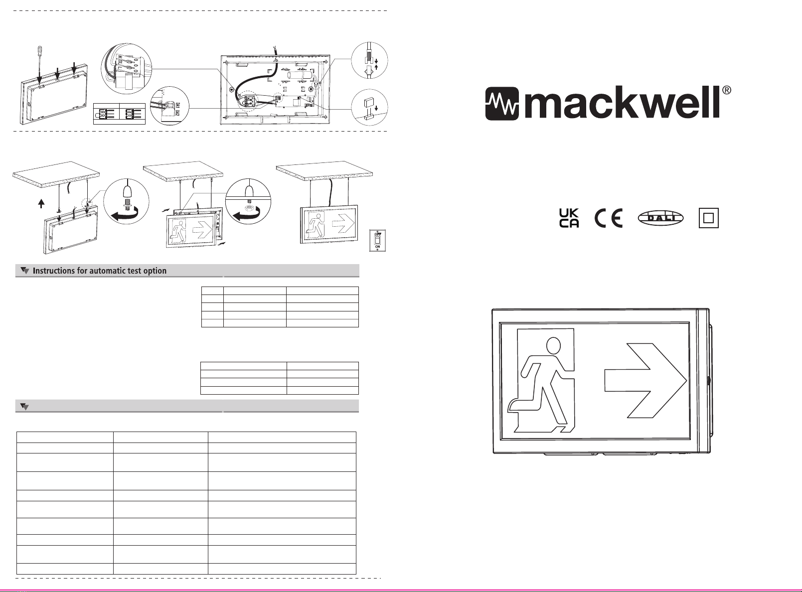
1. Remove the diffuser from the base by screwdriver.
1.
Cut out size: L330 x W120mm.
Refer to step 1 and 2 of ceiling mount .2. Fix the base onto the recessed bracket.
4. Fix the diffuser onto the base.
2. Pry the gear tray and get access to the mounting base.
4. Fix the base onto the ceiling.
Read instructions and check you have all the tools and accessories to complete the installation correctly.
WARNING
1.Switch off before installation or maintenance.
2.Switch on only after complete installation and examination of the circuit.
3.Professional electrician for installation and maintenance only. Turn Off
Power Supply
Installation Procedure
Ceiling Mount
Precautions
Recessed Mount (Recessed kit sold separately)
4.This luminaire is not intended for use in high-risk task area lighting.
DALI wiring
DALI wiring
* Wire“L”“N” to terminal block
* * Wire“L”“N” to terminal block,
Wire 2 x DALI signal wires to terminal on PCB.
* * Wire“L”“N” to terminal block , wire 2 x DALI signal wires to terminal on PCB
3. Punch out the cable entry hole,connect the mains
cable to the terminal, and connect the battery onto the PCB.
Choose maintained or non-maintained mode by connecting or removing the jumper cable.
5.
Fix the luminaire into the ceiling.
6. Switch on, the green LED indicator will light up.
L: Live
Maintained (default) Non-Maintained
SL: Switched Live N: Neutral
LSLN
LSLN
Jumper cable connected Jumper cable removed
3. Punch out the cable entry hole, connect the mains cable to the terminal, and connect the battery onto the PCB.
Fix the mounting base onto wall.
Choose maintained or non-maintained mode by connecting or removing the jumper cable.
* Wire“L”“N” to terminal block
L: Live
Maintained (default) Non-Maintained
SL: Switched Live N: Neutral
LSLN
LSLN
Jumper cable connected Jumper cable removed
5. Fix the housing onto the base. 6. Switch on, the green LED indicator will light up.
Battery
PCBA
XYVEX EX-IP
IP65
LED indication Status Comments
Permanent green System OK
Fast flashing green
(0.1 sec. on -0.1 sec. off)
Function test underway
Slow flashing green
(1 sec. on – 1 sec. off) Duration test
Red LED on Load failure Open circuit / Short circuit / LED failure
Slow flashing red
(1 sec. on -1 sec. off) Battery failure Battery failed the duration test or function test/
Battery is defect / Incorrect battery voltage
Fast flashing red
(0.1 sec. on -0.1 sec. off) Charging failure Incorrect charging current
Binary transmission of Address identification Provides the DALI short address of the fitting via binary
code. Red=1, Green=0. Example: 000011= SA3
Double pulsing green Inhibit mode Switching into inhibit mode via controller
Green and red off Emergency mode Battery operation (Emergency mode)
address via green/red LED
System status is indicated by a bi-colour LED and by a DALI status flag.
1. Instruction for Automatic test function
Once the unit is powered up, a self-diagnostics test will be
automatically initiated:
• Monitoring battery, lamp, charge status constantly.
Run 3mins function test every month.
Run 3H duration test every year.
•
•
Note: All test functions are preset and no need field adjustment.
2. Dual Colour LED Status Indicator Meaning
• Green indicator solid on: Ready/ Normal Operation
• Red indicator flashes: Require service
• One flash, 4s pause Battery disconnected
•• Two flashes, 4s pause Low battery voltage
••• Three flashes, 4s pause Charge board fault
•••• Four flashes, 4s pause AC/DC transfer fault
••••• Five flashes, 4s pause LED lamp fault
Note: When the fault is recovered, press the test button for 2s, the red flashing
indicator will turn green. The fault is cleared, and the unit is back to normal.
3. Button Test
Press test button once run a 30s duration test
Press test button twice within 2s run a 3mins duration test
Press test button 3 times within 2s run a 30mins duration test
Press test button 4 times within 2s run a 1H or 3H duration test
Status indication for DALI Versions
0.75 - 2.5mm²
Solid conductor or
7 stranded wire ends
Cable Size & Strip Length
0.75 - 2.5mm²
Solid conductor or
7 stranded wire ends
Cable Size & Strip Length
1:1
EP-E-EX5-0251B0EPE-EX5
7-123037-2000135
王汝佳
20230901
说明书
深圳依炮尔科技有限公司
Epower Tech Co.,Ltd
B0 首次发行
要求:
285*210mm,70G书写纸,单色双面印刷。图中的字体、
图标、排版位置及颜色等我司提供的PDF文档做,
成品必须清晰整洁,请严格按1:1来不能有模糊或重影、
错位及残缺等现象。
XYVEX EX-IP
285 mm
210 mm
单位用量:1PCS
业务单号:郑丹萍 EP-ZE230713055
成品BOM:1-37000101-006052001 1-37000101-006052002
折叠如图:
285/2 210/2
Read instructions and check you have all the tools and accessories tocomplete the installation correctly.
WARNING
1.Switch off before installation or maintenance.
2.Switch on only after complete installation and examination of the circuit.
3.Professional electrician for installation and maintenance only. Turn Off
Power Supply
4.This luminaire is not intended for high-risk task area lighting.
L
W
L
Normal Operation: The green LED indicator stays on when connected to mains supply. The indicator will turn
off when the mains supply fails, or when the internal charger malfunctions, or when the luminaire is in test mode.
Battery: LiFePO4/ Ni-Cd rechargeable battery pack. Battery should be replaced when it reaches the end of its
lifetime. To avoid damage to the luminiare and ensure its performance, the battery should be replaced with same type.
Test Switch: Press the test button, LED indicator will turn off and the luminaire will be powered by the battery pack. The
light source is non-replaceable. When the light source reaches the end of its lifetime, the whole luminaire shall be replaced.
1. Accessories include screws,
plastic nylon anchors for
fixing on the wall.
The space between two mounting
holes on the wall is 240mm.
2. Pry off the front cover and get access to the
mounting base.
2. Pry off the front cover and get access to the
mounting base.
4. Install the 4 recessed springs onto the base. 5.
Fix the luminaire onto the ceiling.
Finish installation.
Switch on.
1.
Cut out size: L300-315mm x W160-175mm. Four
springs for fixing the luminaire onto the ceiling.
2. Pry off the front cover and get access to the
mounting base.
3. Punch out the hole for mains supply wires. Insert the screw into the nylon anchors, and then fix the mounting base
onto wall. Connect the mains supply wires to the terminal, and connect the battery onto the PCBA.
Choose maintained or non-maintained mode by connecting or removing the jumper cap.
3. Punch out the hole for mains supply wires. Connect the mains supply wires to the terminal, and connect the battery
onto the PCBA. Put the front cover back.
Choose maintained or non-maintained mode by connecting or removing the jumper cap.
4. Put the front cover back. 5. Finish installation. Switch on.
1. Fix hanging rope onto the ceiling.
Press to adjust the length
of the suspension wire
x2
1 2 3 4
180mm
Pendant Mount
L: Live
Maintained (default) Non-Maintained
SL: Switched Live N: Neutral
LSLN
LSLN
Jumper cable connected Jumper cable removed
L: Live
Maintained (default) Non-Maintained
SL: Switched Live N: Neutral
LSLN
LSLN
Jumper cable connected Jumper cable removed
* Wire“L”“N” to terminal block
Battery
PCBA
jumper cap
SL
DALI wiring
wire 2 x DALI signal
wires to terminal on PCB
* Wire“L”“N” to terminal block
Battery
PCBA
jumper cap
SL
DALI wiring
wire 2 x DALI signal
wires to terminal on PCB
3. Punch out the hole for mains supply wires and two rope mounting holes on top of the mounting base. Connect the
mains supply wires to the terminal, and connect the battery onto the PCBA.
5. Finish installation. Switch on.
4. Insert the rope into the mounting hole and secure with nuts.
Put the front cover back.
* Wire“L”“N” to terminal block
Battery
PCBA
jumper cap
L: Live
Maintained (default) Non-Maintained
SL: Switched Live N: Neutral
LSLN
LSLN
Jumper cable connected Jumper cable removed
SL
Choose maintained or non-maintained mode by connecting or removing the jumper cap.
DALI wiring
wire 2 x DALI signal
wires to terminal on PCB
XYVEX WALL
IP40
LED indication Status Comments
Permanent green System OK
Fast flashing green
(0.1 sec. on -0.1 sec. off)
Function test underway
Slow flashing green
(1 sec. on – 1 sec. off) Duration test
Red LED on Load failure Open circuit / Short circuit / LED failure
Slow flashing red
(1 sec. on -1 sec. off) Battery failure Battery failed the duration test or function test/
Battery is defect / Incorrect battery voltage
Fast flashing red
(0.1 sec. on -0.1 sec. off) Charging failure Incorrect charging current
Binary transmission of Address identification Provides the DALI short address of the fitting via binary
code. Red=1, Green=0. Example: 000011= SA3
Double pulsing green Inhibit mode Switching into inhibit mode via controller
Green and red off Emergency mode Battery operation (Emergency mode)
address via green/red LED
System status is indicated by a bi-colour LED and by a DALI status flag.
1. Instruction for Automatic test function
Once the unit is powered up, a self-diagnostics test will be
automatically initiated:
• Monitoring battery, lamp, charge status constantly.
Run 3mins function test every month.
Run 3H duration test every year.
•
•
Note: All test functions are preset and no need field adjustment.
2. Dual Colour LED Status Indicator Meaning
• Green indicator solid on: Ready/ Normal Operation
• Red indicator flashes: Require service
• One flash, 4s pause Battery disconnected
•• Two flashes, 4s pause Low battery voltage
••• Three flashes, 4s pause Charge board fault
•••• Four flashes, 4s pause AC/DC transfer fault
••••• Five flashes, 4s pause LED lamp fault
Note: When the fault is recovered, press the test button for 2s, the red flashing
indicator will turn green. The fault is cleared, and the unit is back to normal.
3. Button Test
Press test button once run a 30s duration test
Press test button twice within 2s run a 3mins duration test
Press test button 3 times within 2s run a 30mins duration test
Press test button 4 times within 2s run a 1H or 3H duration test
Status indication for DALI Versions
Cable Size & Strip Length
0.75 - 2.5mm²
(0.75-1.5mm² for DALI)
Solid conductor or
7 stranded wire ends
Cable Size & Strip Length
0.75 - 2.5mm²
(0.75-1.5mm² for DALI)
Solid conductor or
7 stranded wire ends
Cable Size & Strip Length
0.75 - 2.5mm²
(0.75-1.5mm² for DALI)
Solid conductor or
7 stranded wire ends
1:1
EP-E-EX7-0102B0EPE-EX7
7-123037-2000137
王汝佳
20230901
说明书
深圳依炮尔科技有限公司
Epower Tech Co.,Ltd
B0 首次发行
要求:
285*210mm,70G书写纸,单色双面印刷。图中的字体、
图标、排版位置及颜色等我司提供的PDF文档做,
成品必须清晰整洁,请严格按1:1来不能有模糊或重影、
错位及残缺等现象。
285 mm
210 mm
单位用量:1PCS
业务单号:郑丹萍 EP-ZE230713055
成品BOM:1-37000101-003062044 1-37000101-003062045
折叠如图:
285/2 210/2
IP40
XYVEX WALL


