W134 N5345 Campbell Dr. Menomonee Falls, WI 53051 800-238-7474 262-781-3366 Fax 262-781-4433
I
NSTALLATION
I
NSTRUCTIONS
TD-8 SERIES
DIGITAL-SET TIME DELAY RELAY
901-0000-276
October, 2014 REV B
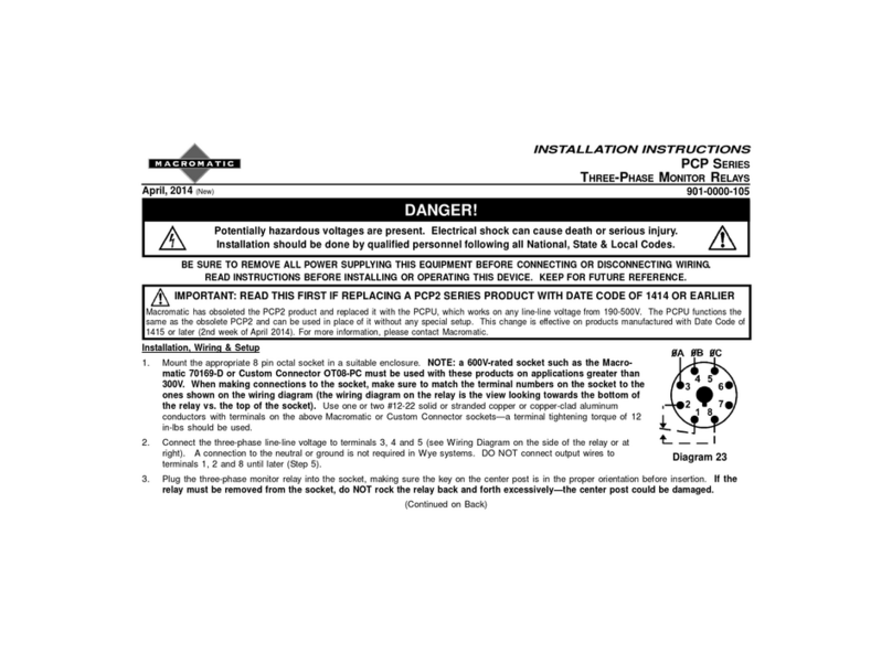
Installation: Mount the appropriate 8 or 11 pin octal socket in a suitable enclosure. Wire the socket per the wiring diagram on the side
of the time delay relay. Make sure to match the terminal numbers on the socket to the ones shown on the wiring diagram (the wiring
diagram on the relay is the view looking towards the bottom of the relay vs. the top of the socket). Use #12-20 solid or stranded copper
or copper-clad aluminum wires with Macromatic sockets and a terminal tightening torque of 7 in-lbs. Plug the time delay relay into
the socket, making sure the key on the center post is in the proper orientation before insertion. If the relay must be removed from the
socket, do NOT rock the relay back and forth excessively—the center post could be damaged.
DANGER!
Potentially hazardous voltages are present. Electrical shock can cause death or serious injury.
Installation should be done by qualified personnel following all National, State & Local Codes.
BE SURE TO REMOVE ALL POWER SUPPLYING THIS EQUIPMENT BEFORE CONNECTING OR DISCONNECTING WIRING.
READ INSTRUCTIONS BEFORE INSTALLING OR OPERATING THIS DEVICE. KEEP FOR FUTURE REFERENCE.
Troubleshooting: If the unit fails to operate properly, check that all connections are correct per the appropriate wiring diagram on the
product. Refer to the description of the function operation on the next page. If problems continue, contact Macromatic at 800-238-7474
Warranty: All Catalog-listed TD-8 Series Time Delay Relays manufactured by Macromatic are warranted to be free from defects in
workmanship or material under normal service and use for a period of five (5) years from date of manufacture.
The following applies to only the TD-881 Series Multi-Function
unit (Figure 1):
Programming is accomplished through the use of two 10-position
DIP-switches. Switches A-D of the left-mounted DIP-switch are used
to select a function (as a guide, see the descriptions of how each
function operates on the reverse side of this sheet). Switches E, F
& G of the same DIP-switch are used to select the time base (t) for
single mode functions and (t1) for dual mode functions. Switches H,
J & K are used to select the time base (t2) for dual mode functions. A
convenient chart is on the side of the product to clearly illustrate how
to set both the function and time base.
The right-mounted 10-position DIP-switch is used to select the time
delay within the time base or bases selected with switches E-K from
the first DIP-switch. Each position on the right-mounted DIP-switch is
marked with a time increment. The required delay, (t) for single mode functions or (t1) and (t2) for dual mode functions, is selected
by moving the switch of each increment to the ON position and adding their corresponding values. NOTE: Dual mode functions can either
have the same or different (t1) and (t2) times as well as different time bases. NOTE: Switches H, J ,& K are only used on dual mode
functions and are not used for single mode functions.
LED Indicator: Green ON--Power, Red ON--Relay Energized
The following applies to all TD-8 Series Single-Function units
(Figure 2):
Programming is accomplished through the use of one 10-position
DIP-switch (single mode functions) or two 10-position DIP-switches
(dual mode functions). Each position on the DIP-switch is marked
with a time increment. The required delay, (t) for single mode
functions or (t1) and (t2) for dual mode functions, is selected by
moving the switch of each increment to the ON position and adding
their corresponding values.
As a guide, a description of how each function operates is on the
reverse side of this sheet.
LED Indicator: Green ON--Power, Red ON--Relay Energized
Figure 1
Figure 2
Top Side
Single Mode Functions Dual Mode Functions
ON ONOFF
COMBINE FOR
TOTAL TIME
SEE CHART ON SIDE
FOR FUNCTION &
TIME BASE SETUP
TIME BASE FUNCTION
A
B
C
D
-
-
-
-
-
-
-
-
-
-
E
F
G
H
J
K
64
256
512
128
32
16
4
8
2
1
-
-
-
-
-
-
-
-
-
-
1ST DELAY2ND DELAY
1
4
2
8
16
1
2
4
8
DUAL
MODE
16
SINGLE
ON ONOFF
TIME DELAY
COMBINE FOR
TOTAL TIME
SEE CHART ON SIDE
FOR FUNCTION &
TIME BASE SETUP
TIME BASE FUNCTION
A
B
C
D
E
F
G
H
J
K
64
256
512
128
32
16
4
8
2
1
t1
1
4
2
8
16
1
2
4
8
DUAL
MODE
16
SINGLE
MODE (t)
RED
-
RELAY
ON
GRN
-
POWER
ON
STATUS
t2
SELECTFUNCTION
ABCD
ONDELAY OFF OFF OFF OFF
INTERVAL ONONOFF OFF OFF
OFF DELAY OFF ONOFF OFF
IOFF
FLASHER (ON)OFF OFF
FLASHER (OFF)ONOFF
WATCHDOG OFF ON
OO
NONOFF
OFF OFF ON
CYCLE (ON)ONOFF
OFF ON
ONONON
ONOFF ONON
OFF ONONON
ONONONON
SINGLE MODE
BASE EFG
BASE
1SOFF ONOFF
0.1M OFF OFF ON
1M ONONOFF
1
1HONON
SINGLE MODE (t)
SELECTTIMEBA
SE
DUAL MODE
(t1)
(t2)
ONE SHOT
TR. DELAYED INT.
ON/OFF DELAY
DELAYED INTERVAL
CYCLE (OFF)
ON DELAY FLASHER
SELECTFUNCTION
FUNCTIONAB
CD
ONDELAY OFF OFF OFF OFF
INTERVAL ONONOFF OFF OFF
OFF DELAY OFF ONOFF OFF
OOOO
FF
FLASHER (ON)OFF OO
FLASHER (OFF)ONOOO
FF
WATCHDOG OFF OO
NO
ONE SHOT F. EDGE ONOON
O
OFF
OFF OO
FF ON
CYCLE (ON)ONOO
FF O
OFF OO
N
ONONOO
OO
N
OO
N
ONOFF ONON
OFF ONONON
ONONONON
SINGLE MODE
EFG
HJK
1SOFF ONOFF
0.1M OFF OFF ON
1M ONONOFF
0.1H ONOFF ON
1H OFF ONON
SEL CTTIMEBA
SE
DUAL MODE
DUALMODE
ONE SHOT-FLASHER
TR. DELAYED INT.
ON/OFF DELAY
DELAYED INTERVAL
CYCLE (OFF)
ONDELAY
/FLASHER
N
NFF
FF
N
N
FF
FF
FF
N
N
FF
FF
N
FF
FF
N
N
FF
TR. ONDELAY
SINGLE SHOT
0
0.1 SONOFF OFF
0.1 SONOFF OFF
0.1 OFF OFF
0.SOFF OFF
0
1SOFF ONOFF
0.1M OFF OFF ON
1M ONONOFF
1
1HONON
1SOFF ONOFF
0.1M OFF OFF ON
1M ONONOFF
0.1H ONOFF ON
1H OFF ONON
0
0.1 SONOFF OFF
0.1 SONOFF OFF
0.1 OFF OFF
0.SOFF OFF
0
OOFF
ON
OOFF
ON
NOTE:SWITCHES H,J,&K ARE ONLYUSED ON DUAL MODE FUNCTIONS
64
COMBINE FOR
TOTAL TIME
IN SECONDS
256
128
512
-
-
-
8
-
32
16
-
-
-
2
-
-
4
-
1
ON OFF
RED
-
RELAY
ON
GRN
-
POWER
ON
STATUS
t
64
-
256
512
-
128
-
-
8
-
32
-
16
-
-
2
-
4
-
1
64
-
256
512
-
128
-
-
8
-
32
-
16
-
-
2
-
4
-
1
ON OFF ON
COMBINE FOR
TOTAL TIME
IN MINUTES
t2
t1
RED
-
RELAY
ON
GRN
-
POWER
ON
STATUS
