manuals.online logo
Brands
  1. Home
  2. •
  3. Brands
  4. •
  5. macromatic
  6. •
  7. Relay
  8. •
  9. macromatic Time Ranger TR-681 Series User manual

macromatic Time Ranger TR-681 Series User manual

I
NSTALLATION
INSTRUCTIONS
TIME RANGERTM PROGRAMMABLE
MULTI-FUNCTION MULTI-RANGE
PLUG-INTIME DELAY RELAY
READ INSTRUCTIONS BEFORE INSTALLING OR OPERATING THIS DEVICE.
KEEP THESE INSTRUCTIONS FOR FUTURE REFERENCE.
WARNING
Potentially hazardous voltages are present. Turn off all power supplying this equipment before connecting or disconnecting wiring.
INSTALLATION
Mount the appropriate 8 pin (Macromatic Product Number
70169-D) or 11 pin (Product Number 70170-D) octal socket in a
suitable enclosure. Wire the socket per diagrams below. Set the
time delay as described per chart on the right and set the function
as described below. Plug unit into socket.
901-0000-250
TR-681 Series
April 2004
Rev B
DIMENSIONS
TROUBLESHOOTING
If the unit fails to operate properly, check that all connections are correct per the appropriate diagram from above. For DC Input Voltages,
make sure the polarity matches the appropriate wiring diagram from above. Use the descriptions of how each function operates on back of
this sheet as a guide to determine if the unit is operating properly. If problems continue, contact Macromatic at 800-238-7474 for assistance.
WARRANTY
All products manufactured by Macromatic are warrented to be free from defects in workmanship or material under normal service
and use for a period of two (2) years from the date of manufacture.
SPECIFICATIONS
Input Voltage: See Product Nameplate for actual
voltage. AC tolerances are +10/-15% @
50/60Hz. DC tolerances are +10/-15%
Output Contact Rating: 10A Resistive @ 240VAC/28VDC
1/2 HP @ 240VAC
Temperature Range: -28º to 65ºC (-20º to 150º F)
Trigger Switch Reset Time: 0.1 seconds minimum. Must be closed
for 0.05% of time range selected
Setting Accuracy: MAX +10%, -0%
MIN +0%, -50%
Dimensions shown are inches (millimeters)
2.4 (60)
1.7
(43)
2.9
(74) 3.1
(79)
SELECTING A FUNCTION
The unit comes with 8 field selectable functions. Determine the
desired function using the chart on the top of the unit or see the
descriptions on page two (2) of these instructions for the available
functions and timing charts. Position the rotary switch to the
number that matches the desired function. DO NOT CHANGE
THE FUNCTION WITH THE POWER APPLIED TO THE UNIT.
NOTE: For functions using a trigger signal, the Control Switch is a
dry-type contact (applying voltage to Pins 5 & 6 could damage the
unit). Do not use solid state input devices as the Control Switch
because problems with leakage current may occur.
SELECTING AN INPUT VOLTAGE
This unit works on either 120VAC or 24VAC/DC. Select Wiring
Diagram 43 or 44 from below for proper connections. For DC
input voltages make sure the polarity matches the appropriate
diagram.
WIRING
A wiring diagram is also provided on the side of the time delay
relay.
DIAGRAM 43 DIAGRAM 44
SETTING THE TIME DELAY
This unit comes with 16 built-in time
rangesinoneunit. First, determinethe
desired time range from the Timing
Range Chart located on the wide side
of the unit or from the table on the left.
Position the rotary switch to the letter
that matches the desired time range.
DO NOT CHANGE THE SETTING OF
THIS SWITCH WITH POWER
APPLIED TO THE UNIT. Finally,
adjust the time delay within the
programmed time range by adjusting
the knob located on the top of the unit.
NOTE:the tick marksare forreference
only.
Dial Timing
Setting Range
A 0.2 - 1.7 Sec
B 1.5 - 8 Sec
C 3 - 15 Sec
D 4 - 22 Sec
E 5 - 30 Sec
F 7 - 35 Sec
G 8 - 44 Sec
H 10 - 50 Sec
I 35 Sec - 4 Min
J 3 - 20 Min
K 5 - 35 Min
L 10 - 55 Min
M 15 - 70 Min
N 30 - 90 Min
O 40 - 100 Min
P 50 - 120 Min
TIMING RANGE
CHART
MACROMATIC CONTROLS LLC ! 6625 W. MILL ROAD !MILWAUKEE, WI 53218
TELEPHONE: 800-238-7474 !414-358-2600 ! FAX:414-358-2626
WWW.MACROMATIC.COM
DIAL FUNCTION OPERATION TIMING CHART
SETTING
INSTALLATION
INSTRUCTIONS
TIME RANGERTM MULTI-FUNCTION MULTI-RANGE
TIME DELAY RELAY
1ON/OFF
DELAY
2TRIGGERED
ON DELAY
3OFF DELAY
4RETRIGGERABLE
SINGLE SHOT
5ON DELAY
6ON DELAY
7INSTANTANEOUS
ON
8INTERVAL ON
Upon application of control power, the time delay relay is ready to
accept trigger signals. Upon closure of the trigger signal, the preset
time begins. At the end of the preset time, the relay contacts will
transfer. Upon opening of the trigger signal, the preset time begins.
At the end of the preset time, the output contacts return to their
normal condition.
Upon application of the input voltage, the time delay relay is ready to
accept trigger signals. Upon application of the trigger signal, a
preset time begins (trigger must remain closed throughout the preset
time). At the end of the preset time, the relay energizes and remains
energized until trigger signal is opened.
Upon application of input voltage, the time delay relay is ready to
accept trigger signals. Upon application of the trigger signal, the
relay contacts transfer and hold. Upon release of the trigger signal,
the preset time begins. At the end of the preset time, the relay
contacts return to their normal condition. Any application of the
trigger signal will reset the time.
Upon application of input voltage, the time delay relay is ready to
accept trigger signals. Upon application of the trigger signal, the
relay contacts transfer and the preset time begins. At the end of the
preset time, the relay contacts return to their normal condition unless
the trigger signal is opened and closed prior to time out (before pre-
set time elapses). Continuous cycling of the trigger signal at a rate
faster than the preset time will cause the relay contacts to remain
closed.
Upon application of input voltage, the preset time begins. At the end
of the preset time, the relay contacts transfer. Input voltage must be
removed and reapplied to reset the time delay relay.
Same function as Position 5
Uponapplicationsof input voltage, the relay contacts transfer. Power
must be removed and reapplied to reset the relay
Upon application of input voltage, the relay contacts transfer and the
preset time begins. At the end of the preset time, the contacts return
to their normal condition. Input voltage must be removed and
reapplied to reset the time delay relay.
○○○○○○○○○○○○○○○○○○○○○○○○○○○○○○○○○○○○○○○○○○○○○○○○○○○○○○○○○○○○○○○○○○○○
○○○○○○○○○○○○○○○○○○○○○○○○○○○○○○○○○○○○○○○○○○○○○○○○○○○○○○○○○○○○○○○○○○○○
○○○○○○○○○○○○○○○○○○○○○○○○○○○○○○○○○○○○○○○○○○○○○○○○○○○○○○○○○○○○○○○○○○○○
○○○○○○○○○○○○○○○○○○○○○○○○○○○○○○○○○○○○○○○○○○○○○○○○○○○○○○○○○○○○○○○○○○○○
○○○○○○○○○○○○○○○○○○○○○○○○○○○○○○○○○○○○○○○○○○○○○○○○○○○○○○○○○○○○○○○○○○○○
○○○○○○○○○○○○○○○○○○○○○○○○○○○○○○○○○○○○○○○○○○○○○○○○○○○○○○○○○○○○○○○○○○○○○
○○○○○○○○○○○○○○○○○○○○○○○○○○○○○○○○○○○○○○○○○○○○○○○○○○○

Other macromatic Relay manuals

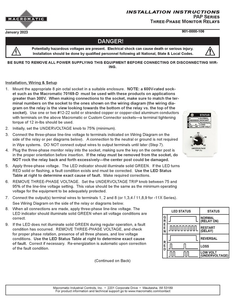
macromatic PAP Series User manual

macromatic

macromatic PAP Series User manual

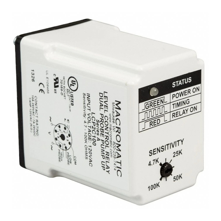
macromatic LCP Series User manual

macromatic

macromatic LCP Series User manual

macromatic PAP Series User manual

macromatic

macromatic PAP Series User manual

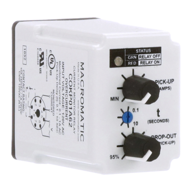
macromatic COKP Series User manual

macromatic

macromatic COKP Series User manual

macromatic MDB Series User manual

macromatic

macromatic MDB Series User manual

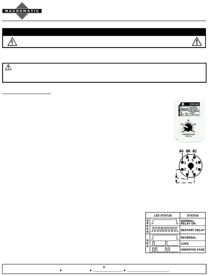
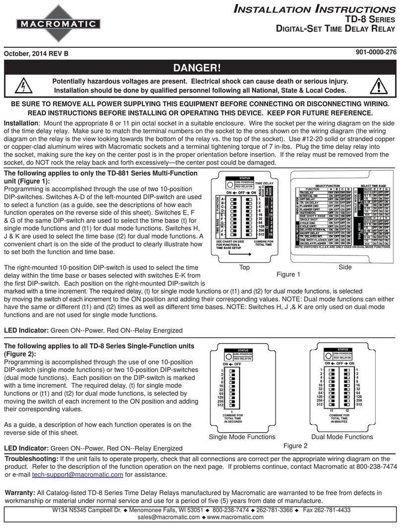
macromatic TD-8 Series User manual

macromatic

macromatic TD-8 Series User manual

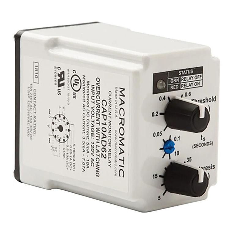
macromatic CAP Series User manual

macromatic

macromatic CAP Series User manual

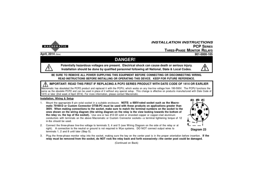
macromatic PCP series User manual

macromatic

macromatic PCP series User manual

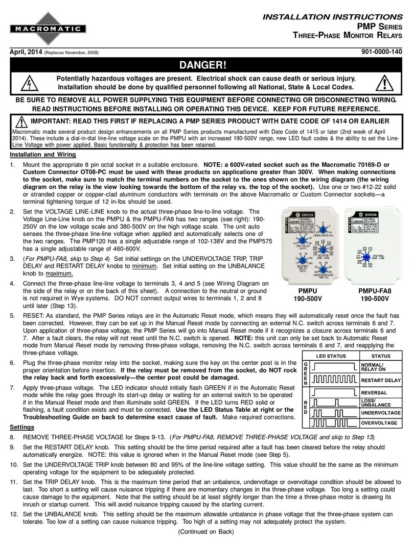
macromatic PMP Series User manual

macromatic

macromatic PMP Series User manual

macromatic PAP Series User manual

macromatic

macromatic PAP Series User manual

Popular Relay manuals by other brands

Vantage Hearth RadioLink AccentPoint Relay Station II APREL installation manual

Vantage Hearth

Vantage Hearth RadioLink AccentPoint Relay Station II APREL installation manual

Chauvin Arnoux THYRITOP 101 Series manual

Chauvin Arnoux

Chauvin Arnoux THYRITOP 101 Series manual

Berker RolloTec 2975 operating instructions

Berker

Berker RolloTec 2975 operating instructions

ABB SPAF 140 C User manual and technical description

ABB

ABB SPAF 140 C User manual and technical description

Omron MK-I - datasheet

Omron

Omron MK-I - datasheet

ABB CM Instruction leaflet

ABB

ABB CM Instruction leaflet

Pilz PNOZ X1 operating instructions

Pilz

Pilz PNOZ X1 operating instructions

HOKKIM DAMF-5 manual

HOKKIM

HOKKIM DAMF-5 manual

bihl+Wiedemann BWU2236 user manual

bihl+Wiedemann

bihl+Wiedemann BWU2236 user manual

Sangoma S503 Hardware Interface Manual

Sangoma

Sangoma S503 Hardware Interface Manual

EUCHNER ESM-BA7 Series operating instructions

EUCHNER

EUCHNER ESM-BA7 Series operating instructions

GE MDP instruction manual

GE

GE MDP instruction manual

Omron J7KNA-AR datasheet

Omron

Omron J7KNA-AR datasheet

OEZ MINIA MMR-X3-001-A230 Instructions for use

OEZ

OEZ MINIA MMR-X3-001-A230 Instructions for use

Show Tec RP-405 MKII manual

Show Tec

Show Tec RP-405 MKII manual

GE IFCV51AD instructions

GE

GE IFCV51AD instructions

AutomationDirect RTD320 operating instructions

AutomationDirect

AutomationDirect RTD320 operating instructions

Sel SEL-300 Series Application guide

Sel

Sel SEL-300 Series Application guide

manuals.online logo
manuals.online logoBrands
  • About & Mission
  • Contact us
  • Privacy Policy
  • Terms and Conditions

Copyright 2025 Manuals.Online. All Rights Reserved.