MACTRAP GREASE BOSS G15 EASY CLEAN Quick start guide

HOW GREASE REMOVAL UNITS WORK
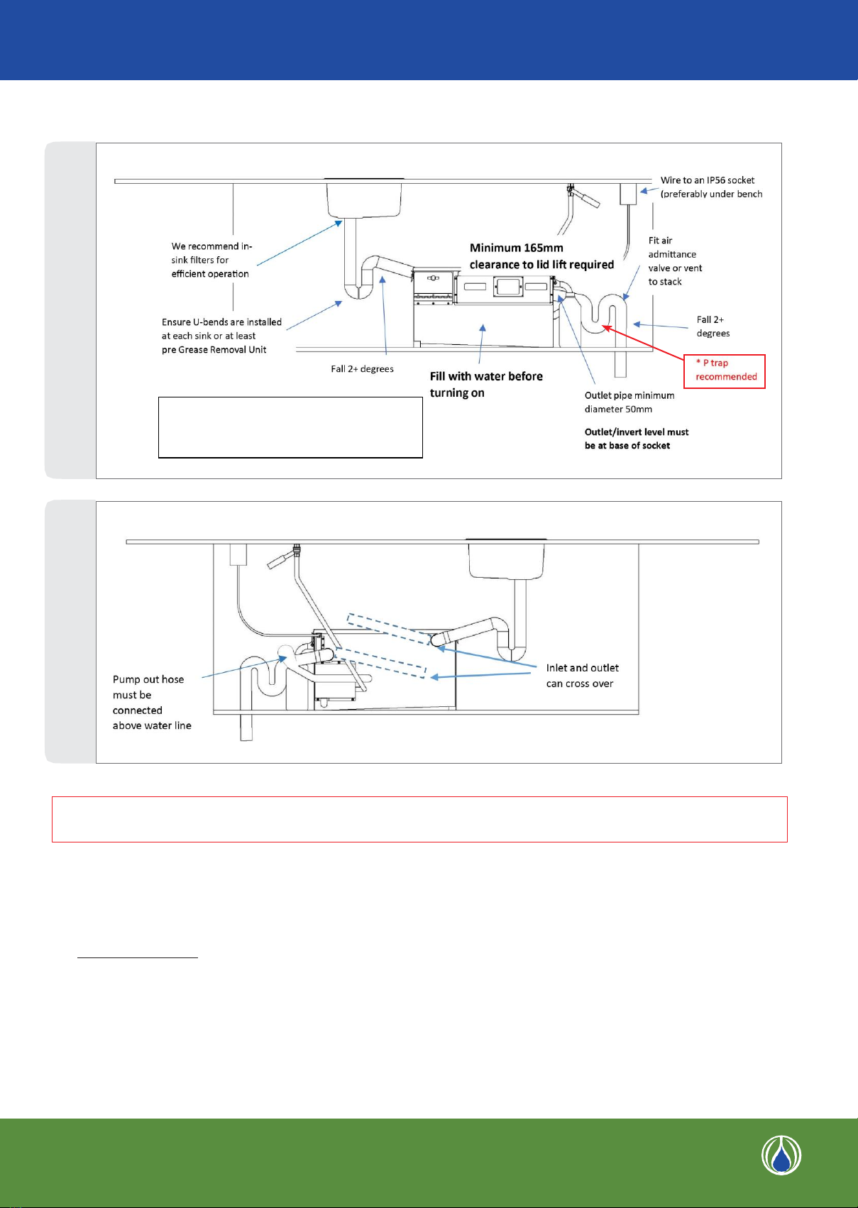
The Grease Boss can be installed internally and requires
minimal operator maintenance inside the machine.
Wastewater enters the unit through a removable 2mm
gauge filter basket which captures food solids which
escape the customer sink filter. This basket is removed
from the front of the machine allowing minimum head
room when installing.
Waste fats, oil and grease (FOG) can be collected in a
disposable container (such as a plastic milk bottle) and put
with other rubbish collection, or into a washable
collection container.
In the trap, FOG rises to the surface where it is attracted
by a rotating FOG attraction tube. This FOG is removed via
a wiper blade into an external collection container. Tests
show that over 98% of FOG is removed. A PLC controlled
hot water injection programme ensures FOG is pliant and
always recoverable by keeping temperature to a level that
will not allow fats to solidify - usually the hot water used in
a normal day’s operating allows this.
The FOG extraction cycle continues intermittently for 24
hours at which time a wash and clean out cycle resets
the machine leaving it tidy and clean for the next day’s
operation. On final daily cycle completion when FOG has
been removed to external collection, water with the FOG
removed exits from the unit into the wastewater system.
WHERE CAN GREASE BOSS BE USED
•
Where there is no room for an external passive trap or
as an alternative to a passive trap.
•
Where under bench height space is tight.
•
Where there are self-cleaning ovens*
•
Where there is a dishwasher*
•
Combi-oven specific options available
*conditions applicable
DIMENSIONS
G15 SPECIFICATIONS
Material
Max Inflow Rate
Treatment Capacity
FOG Removal Rate
Heating
304 Stainless Steel
1.5L/sec (restrictor set for 0.5L/sec
where local authorities set limitation)
<350L passive capacity
<11.kg/Hour
Uses operator’s sink waste and hot
water connected to hot water supply
Motor
Static Capacity
PLC Control
Grease Retention
230V 11RPM
100 Litres
230v, 50Hz, Crouzet 24-Hour
Operation
<20kg
2
For more information contact MACTRAP
Phone: +64 7 549 0414 Mobile: +64 274 978 791
Email: info@mactrap www.mactrap.co.nz
Note: inlet and outlet diameters are 50mm

For more information contact MACTRAP
Phone: +64 7 549 0414 Mobile: +64 274 978 791
Email: info@mactrap
www.mactrap.co.nz
*IMPORTANT: A P TRAP OR SIMILAR IS RECOMMENDED AFTER OUTLET TO MITIGATE POSSIBLE BACKFLOW ODOUR
IF RISK FROM PUBLIC / BUILDING UTILITY LINE IS POSSIBLE.
CORRECT INSTALLATION
ENSURE OUTLET PIPE SIZE IS NO SMALLER DIAMETER THAN THE INLET PIPE
•
Use flexible couplings to inlet and outlet.
•
Inlet and outlet can be crossed over at rear to suit orientation
•
Connect solenoid valves to hot water (HW) line
•
Fit a tap connection to HW line to allow tank service, removal and emergency shut off.
•
Ensure 1:40 fall at all times for inlet and outlet pipes.
•
Do not use a compression hose on inlet side.
•
Ensure unit is filled with water prior to switching on power source.
•
It is advisable to leave power on to retain integrity of default settings.
•
Check correct invert levels herein shown.
•
HW temperature at sink should be >41oC for average dailyoperation but below scald temperature to allow entry and service.
3
)
FRONT VIEW
REAR VIEW
Note: Inlet and outlet sockets are 50mm. If the
outlet diameter is reduced, the inlet diameter
must be reduced to match.

For more information contact MACTRAP
Phone: +64 7 549 0414 Mobile: +64 274 978 791
Email: info@mactrap
www.mactrap.co.nz
PUMP BOX INSTALLATION
The rear mounted pump and solenoid valve cover is removed by 4 screws for service - note detail below.
4
PROGRAMME
The PLC will display which operation is taking
place, or if there is a fault.
FAULT
Indicated when PLC window flashes on andoff.
(Note the fault light also occurs when the lid is
open).
POWER ON
When the PLC window is illuminated.
WARNING: ALL SYSTEMS 240V. TURN OFF MAINS
BEFORE SERVICE OR REMOVING COVER
Options for outlet connection. Connection canbe
changed 180 degrees
HW connection to solenoid valve- ensure a tap is
inserted before the solenoid valve for service and
emergency stop.
Pump out connection - link to outlet at a heigh
above outlet invert to avoid possible siphon or
backflow
PUMP BOX
PLC CONTROL

WARNING: ALWAYS TURN OFF POWER PRIOR TO REMOVING WIPER OR ROLLER UNITS AND IF OPENING
ELECTRICAL COVERS
GETTING STARTED
STEP 1 Check the unit is plumbed in correctly (and that all parts can be accessed).
STEP 2 Fill unit with water.
STEP 3 Connect to electric supply (via a standard 10amp plug. RCDs are recommended for ultimate safety).
STEP 4 Switch power on at mains (the PLC screen will light to show power on and to advise detail and programme).
The unit is pre-programmed so there is no need to set the timer and cycle programmes.
STEP 5 Carry out all housekeeping requirements outlined in this manual.
ATTENTION
•
If the tank is emptied or pumped out it is advisable to refill with cold water to at least 60%full.
•
The Grease Boss is designed to trap and remove free floating grease oils and fats. It is not designed to process solids
and will lose efficiency if not maintained as solids will build up inside.
•
The solids basket provided protects the unit from solid food waste build up. The unit requires a daily check of the filter
basket to remove solids build up. Empty these solids to rubbish.
•
To help ensure the highest efficiency, reduce solid food waste by installing primary sink strainers or by scraping waste
into bins.
•
Consult your supplier in the event of increased loadings to the Grease Boss.
•
Do not use harmful detergents to clean the Grease Boss
•
Service contracts by approved engineer are available and recommended.
UNIT EFFICIENCY
CAUTION: The passing of dishwasher waste and self-cleaning oven waste through the MACTRAP Grease Boss may affect
the efficiency of the special roller attraction of fats and oils in the Grease Boss. High use of certain emulsified oils and
homogenised dairy milks may also affect efficiency.
This type of FOG waste may not be collected as effectively as free flowing fats and oils which can result in effluent
readings carried out by some testing laboratories, showing higher Mg/litre fats and oils readings than specified.
This problem occurs with all grease trap systems including passive traps. We recommend customers carefully check the
allowable fats and oil effluent permitted in their specific local authority consent. Customers should include simple
management processes to reduce the amount of emulsified oils and milk products entering the grease removal system to a
minimum.
WARRANTY
Email: info@mactrap www.mactrap.co.nz
For more information contact MACTRAP
Phone: +64 7 549 0414 Mobile: +64 274 978 791
5
A 12 month warranty applies to parts and materials for this MACTRAP GRU. This warranty does not include any labour,
cleaning out or maintenance. If the MACTRAP GRU is not installed and operated as per these operation guidelines, the
warranty will be void.

For more information contact MACTRAP
Phone: +64 7 549 0414 Mobile: +64 274 978 791
Email: info@mactrap
www.mactrap.co.nz
WARNING: UNIT IS 240 V - TURN POWER SUPPLY OFF BEFORE REMOVING ROLLER OR OPENING
ELECTRICAL PANEL.
MAINTENANCE
FILTER BASKET AND FOG CAPTURE CONTAINER
WIPER / ROLLER
This should be removed and cleaned as part of your periodic servicing but for most of the time the wash cycle will keep it
clean and clear. Inspect wiper blade during periodic inspection for wear or disfiguration.
The wiper chute is removed by lifting out. To replace, lift back in and position the two locating holes in the chute with the
two locating studs on the tank sidewall.
NOTE: Keep solids especially coffee grinds, onion peel, bones, utensils and plastics out of the unit. This is important to
ensure the efficient operation of the extraction process and prevent any build-up of rubbish in the chute area.
•
To assist and limit problems of internal solids build up, before pre-wash rising, wipe any dairy waste off dishes /utensils
into rubbish.
•
We recommend permanent sink solids filters be used in addition to the MACTRAP filterbasket.
•
Use hot water for washing
6
•
Open door and remove filter basket
•
Empty contents to waste bin
•
Clean and replace
•
Close door
Remove waste fat, oil and grease collection container
(old milk bottles are ideal to use) and put in refuse.
Wiper chute cleaning nozzle
FOG collection roller
Wiper blade affixed to collection chute
MONTHLY
REGULAR

For more information contact MACTRAP
Phone: +64 7 549 0414 Mobile: +64 274 978 791
Email: info@mactrap
www.mactrap.co.nz
TROUBLE SHOOTING
PROBLEM
CAUSE AND SOLUTION
Not extracting oil
PLC indicating fault
IS THE POWER ON?
PLC window will be illuminated when power is on.
Check to be sure the power is on and the time control is set correctly. Check mains
connection. If power is being supplied and there is still no display check fuses or
contact your supplier.
Check the wiper is in position.
ARE REMOVABLE PARTS CLEANED?
Remove the lid and clean away any build-up that may be present in the wiper blades,
collection chute or outlet tray. Ensure that the wiper blades are located properly in
place with the wiper blades contacting the roller. Replace wiper blades when worn.
Warning: This trap contains 240V moving parts - turn off power before removing
wiper or roller units
CHECK THE SKIMMING AND HEATING CYCLES ARE WORKING
The GREASE BOSS operates 4 cycles daily. Each cycle starts with a hot water wash then
a timed FOG extraction period followed by a rinse.
If water temp rises above 42oC during the day the unit will turn on/off regularly in 5
minute intervals.
ROLLER- make sure that you can hear the noise of the roller turning. If the motor can
be heard but the roller is not turning then check the axles and drive couplings that link
the motor to the roller. If the roller motor does not display “ON”, the motor must be
checked by Mactrap for possible replacement.
MAKE SURE WIPER BLADE ASSEMBLY IS SECURE
Position wiper blade assembly over the oil chute guide and secure to locator plate.
Check the condition of the wiper blades as some acids and cleaning liquids may cause
deterioration over time and a new blade may be required.
No hot water supply
Check hot water connection to solenoid is on.
Check spray functions are working.
If water influent is too hot (over 65oC) collection efficiency will be affected.
Pump out fail
Check pump inlet for blockage
Check pump circuit breaker
Replace pump if non-functioning
7
NOTE: DO NOT CLEAN ROLLER WITH DETERGENT AS THIS WILL AFFECT THE OPERATION OF THE GREASE TRAP

For more information contact MACTRAP
Phone: +64 7 549 0414 Mobile: +64 274 978 791
Email: info@mactrap
www.mactrap.co.nz
TROUBLE SHOOTING
8
PROBLEM
CAUSE AND SOLUTION
Excessive water is
observed in the grease
collection container
CYCLE SETTINGS
Check the roller time Per Cycle settings are not set for too long a period. The unit
should not run extensively after the grease and oils have been extracted. The Grease
Boss is programmed for safe efficient operation so this aspect should only need
checking during annual service. Refer to service agent or Mactrap for assistance.
CHECK WATER FLOW
Make sure that the water flow to the unit does not exceed the rated flow and that there
are no drain line blockages downstream from the unit.
LOW LEVEL OF OIL WASTE
If only a relatively small amount of oil is present in the wastewater, the amount of water
that is collected in the oil bin can be more than that of the oil. Adjust the cycle timing so
as to reduce the cycle duration.
Check blades are in contact with roller.
Water overflows from
the unit
HAS THE STRAINER BASKET BEEN MAINTAINED?
If water overflows from the inlet chamber the basket may need emptying. Remove,
clean and re-install.
Solids may have built up and blocked the outlet –clear the outlet and drain the line.
DOES THE INLET GASKET NEED REPLACING?
General overflowing can also result from a worn inlet gasket or a blocked outlet pipe.
Replace gasket and clean all possible blockages downstream of the unit.
Check outlet is not blocked.
HAS SEDIMENT BEEN ALLOWED TO BUILD UP OVER TIME?
Over time, depending on how the unit has been operated, sludge could build up at the
bottom of the unit and block the path of the flow underneath the outlet baffle. Clean as
per maintenance instructions. Build up may severely reduce efficiency of unit and lead
to overflow.
Odour Reported
HAS MAINTENANCE BEEN CARRIED OUT?
Ensure all recommended maintenance is carried out.
Check backflow prevention from sewer line and vent the outlet.
Check for scum adhesion especially sour milk froth around the liquid surface level,
skim off occasionally or use sink shower to rinse inside with warm water.
Flush occasionally with clear hot water.
Water level lowers
SIPHONING
This results in a reduced level in the unit caused by the effect of “siphoning”. This
occurs in particular installations where the downstream piping of the unit is not
properly installed. If this occurs, turn off the unit immediately and consult the plumber
or the distributor for more advice.
Check the water level. Do not run dry or empty without refilling with water.
Note: Do not clean roller with detergent as this will affect the operation of the unit.
Table of contents
Other MACTRAP Water Filtration System manuals
Popular Water Filtration System manuals by other brands

NuAire
NuAire IAQBOX Series Installation and Maintenance

Oase
Oase Bitron 9C Directions for use

PROSEP FILTER SYSTEMS
PROSEP FILTER SYSTEMS RO-pro-325 Operation & installation instruction manual

Nederman
Nederman FlexFilter user manual

Waterite
Waterite Vectapure II RO-4042H Installation and owner's manual

Bullard
Bullard AirGladiator AGLDTR1 user manual